CN100504652C - Image heating apparatus and pad sheet therefor - Google Patents
Image heating apparatus and pad sheet therefor Download PDFInfo
- Publication number
- CN100504652C CN100504652C CNB2005101164315A CN200510116431A CN100504652C CN 100504652 C CN100504652 C CN 100504652C CN B2005101164315 A CNB2005101164315 A CN B2005101164315A CN 200510116431 A CN200510116431 A CN 200510116431A CN 100504652 C CN100504652 C CN 100504652C
- Authority
- CN
- China
- Prior art keywords
- pad
- sheet material
- heating member
- superficial layer
- image
- Prior art date
- Legal status (The legal status is an assumption and is not a legal conclusion. Google has not performed a legal analysis and makes no representation as to the accuracy of the status listed.)
- Expired - Fee Related
Links
Images


Classifications
-
- G—PHYSICS
- G03—PHOTOGRAPHY; CINEMATOGRAPHY; ANALOGOUS TECHNIQUES USING WAVES OTHER THAN OPTICAL WAVES; ELECTROGRAPHY; HOLOGRAPHY
- G03G—ELECTROGRAPHY; ELECTROPHOTOGRAPHY; MAGNETOGRAPHY
- G03G15/00—Apparatus for electrographic processes using a charge pattern
- G03G15/20—Apparatus for electrographic processes using a charge pattern for fixing, e.g. by using heat
- G03G15/2003—Apparatus for electrographic processes using a charge pattern for fixing, e.g. by using heat using heat
- G03G15/2014—Apparatus for electrographic processes using a charge pattern for fixing, e.g. by using heat using heat using contact heat
- G03G15/206—Structural details or chemical composition of the pressure elements and layers thereof
Abstract
An image heating apparatus includes a heating rotatable member for heating an image on a recording material in a heating nip; a belt for cooperating with the heating rotatable member to form a heating nip; a pad for urging the belt toward the heating rotatable member at the heating nip; and a sheet covering a surface of the pad opposed to the heating rotatable member, the sheet being slidable on the belt, wherein includes a surface layer having a low friction property and a base layer having a tensile strength of 300-600 MPa.
Description
Invention field
The present invention relates to a kind of being used for to the image heater of the heating of the image on the recording medium and the pad that is used for this image heater.As the example of this image heater, can list a kind of fixing fixing device of the not still image that is formed on the recording medium, a kind of that makes by adding the glossiness aggrandizement apparatus etc. that photographic fixing image on the thermal recording media increases the glossiness of this photographic fixing image.This image heater can be used for electrophotographic copier, electrophotographic printer, electrofax facsimile recorder etc.
Background technology
As mentioned above, electrophotographic image forms for example above-mentioned electrophotographic copier of device, electrophotographic printer, electrofax facsimile recorder or its analog and adopts a kind of fixing device that is used for the not still image that heat fixation forms by toner.Relevant this fixing device has proposed the different fixing device of various heating means, and some in them have been manufactured into the goods of commericially feasible.The heating means type that relevant this fixing device adopts can be that strap clamp closes method, wherein for example, utilizes pressing piece to keep the photographic fixing band to be pressed on the fixing roller with thermal source.
As the example of the box-like fixing device of this strap clamp, the Japanese documentation spy opens flat No.9-34291 and discloses one.This fixing device provides the fixing roller that is used to heat (following will be called heat fixing roll); Between itself and this heat fixing roll, form the band of photographic fixing pressing portion; And keep the pressure pad of this band towards heat fixing roll.
The pressure pad of the above-mentioned type fixing device is formed by rubber or similar substance.Therefore, the friction between band and the pressure pad is quite big, causes the picture recording medium to transmit the problem of a class such as mistake with respect to the position deviation of its epigraph, recording medium.
Therefore, Japanese patent application document spy opens flat No.2004-206105 and discloses a kind of like this fixing device, the pressure pad of this fixing device suitably be coated with a slice cross with the right surface of above-mentioned zone face and friction much smaller than the material of this pressure pad material (rubber).
This sheet (following will be called pad) is formed by basic unit with the two-layer unporforated film that this basic unit is clipped in therebetween.Substrate be one by cloth coated with the fiberglass braided one-tenth of fluoride resin, two unporforated films are formed by PTFE.
In addition, for example proposed with lubricator that silicone oil applies the inside surface of the band of band forms in the form of a ring, some with lubricator apply the inside surface of band and the fixing device that constitutes has dropped into actual use.
Japanese patent application document spy opens flat Nos.2002-148970 and 2003-107936 discloses such fixing device, the feature of this fixing device is that not only pressure pad provides the pad of aforementioned friction much smaller than this pressure pad self, is also that this pad provides to cross surface and the size sizable annular knurl right with zone face.In addition, some have dropped into actual use as disclosed those fixing devices in above-mentioned patented claim document.
Crossing the surface right with zone face, is that annular knurl can reduce contact point quantity between the inside surface of this pad and this band on the friction sheet at the above-mentioned pad on the pressure pad, thereby reduces the total friction between the inside surface of this pad and this band.
For pad not only as mentioned above the inside surface of annular knurl but also band also coated with the lubricant situation of oils for example, interval between the annular knurl on this gasket surface can keep for example oils of this lubricant effectively, helps further to reduce the friction between the inside surface of this pad and this band.
Yet above-mentioned prior art may cause following problem.
That is, in the fixing device situation that adopts the box-like fixation method of above-mentioned strap clamp, the inside surface of endless belt slides on pressing piece in fixing.When it slided, the top layer of pad was the wearing and tearing gradually via friction of fluoride resin (PFA) film.Along with the rubbing wear of fluorinated film, this film stretches.As a result, endless belt becomes and rotates instability.In other words, this class fixing device is not satisfied with regard to durability.
As mentioned above, according in the fixing device situation of above-mentioned arbitrary prior art, along with the increase of device accumulation use amount, the friction between pad and the photographic fixing band increases gradually, finally causes the speed of this photographic fixing band to become different in the peripheral speed of heat fixing roll.Therefore, occurred departing from its position relation with respect to its epigraph as the recording medium printed sheet that transmits via the photographic fixing band; This recording medium printed sheet is by the problem of classes such as mistake transmission.This is to depend on the speed of photographic fixing band because the recording medium printed sheet is the transfer rate of carrying out image fixing.
On the other hand, compare with the above-mentioned pad of being made by a piece of cloth, wearing quality is better, and this cloth is by fiberglass braided the forming coated with fluoride resin (PFA).Yet its frictional resistance is bigger, may produce above-mentioned because the problem that the load that big frictional resistance causes increases.
Simultaneously, when the peripheral speed of photographic fixing band when switching to low speed at a high speed because shake may appear in bigger friction, make the rotation instability of this photographic fixing band.When the temperature and humidity of environment was high, shake also may appear.
Summary of the invention
Fundamental purpose of the present invention provide a kind of with regard to the durability of pad that the photographic fixing band abuts against its slip the image heater better than the image heater of foundation prior art, provide a kind of image heater that can be used for to realize the pad of above-mentioned purpose simultaneously.
According to an aspect of of the present present invention, provide a kind of image heater to comprise: rotatable heating member is used for adding image on the thermal recording material adding hot pressing portion; Band, being used for cooperating with described rotatable heating member adds hot pressing portion with formation; Pad is used in the described hot pressing portion that adds described band being pushed to described rotatable heating member, and described pad has the superficial layer of elastic layer in a side relative with described rotatable heating member; And sheet material, cover described pad and described rotatable heating member facing surfaces, described sheet material can slide on described being with, wherein, described sheet material comprise one have low frictional properties matter and can described with on the superficial layer that slides, and the basic unit of making by heat-resistant synthetic resin, described basic unit has the thickness of 75 μ m to 300 μ m, and tensile strength is 300-600Mpa.
In case consider following explanation to the preferred embodiment of the present invention in conjunction with the accompanying drawings, these and other purpose of the present invention, feature and advantage will become more obvious.
Brief description of drawings
Fig. 1 is the diagrammatic sketch that is used to illustrate according to the structure of first sample of pad of the present invention.
Fig. 2 is the diagrammatic sketch that is used to illustrate according to the structure of second sample of pad of the present invention.
Fig. 3 is the diagrammatic sketch that is used to illustrate according to the structure of the 3rd sample of pad of the present invention.
Fig. 4 is the diagrammatic sketch that is used to illustrate according to the structure of the 4th sample of pad of the present invention.
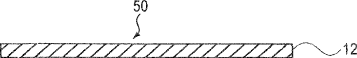
Fig. 5 is used to illustrate that first compares the diagrammatic sketch of pad.
Fig. 6 is used to illustrate that second compares the diagrammatic sketch of pad.
Fig. 7 is used to illustrate that the 3rd compares the diagrammatic sketch of pad.
Fig. 8 is used to illustrate that the 4th compares the diagrammatic sketch of pad.
Fig. 9 is the schematic cross sectional views of typical fixing device.
Figure 10 is the diagrammatic sketch that is used to illustrate the structure of elastic component.
Figure 11 is the synoptic diagram that is used to illustrate according to the manufacture process of the first and the 3rd sample of pad of the present invention.
Figure 12 is the diagrammatic sketch that is used to illustrate according to the structure of pad of the present invention.
Figure 13 is the diagrammatic sketch that explanation is used for pad is carried out the pad manufacturing step of annular knurl.
Figure 14 is the diagrammatic sketch that is used to illustrate the structure and the layout of annular knurl.
Figure 15 is the synoptic diagram that is used to illustrate according to the manufacture process of the second and the 4th sample of pad of the present invention.
Figure 16 is the schematic cross sectional views that typical image forms device.
DETAILED DESCRIPTION OF THE PREFERRED
Below, preferred embodiments of the present invention will be described in detail with reference to the accompanying drawings.By the way be, in following examples of the present invention, can be according to the present invention the needs of applied device construction and the needs of the applied various conditions of the present invention, change size, material and the shape of member and their position relation etc.In other words, following examples of the present invention are not used in and limit the scope of the invention.
Can be used as a kind of fixing fixing device of the not still image that is formed on the recording medium or a kind of that makes according to image heater of the present invention by adding the glossiness aggrandizement apparatus that photographic fixing image on the thermal recording material increases the glossiness of this photographic fixing image.This image heater can be used for the image processing system such as one of employing electrophotographic image formation method of classes such as duplicating machine, printer, facsimile recorder.
With reference to a kind of fixing device following examples of the present invention are described.
The present invention is intended to durability by reinforced gasket the photographic fixing band of fixing device and cover friction between the pad of pressing piece of this fixing device and maintain one low-level.
In addition, it is intended to prevent the phenomenon when the peripheral speed of photographic fixing band this photographic fixing band and the mutual of short duration adhesion of paper when switching to low speed at a high speed, in other words, and their phenomenons inter-adhesive and that slide.
At first, with reference to Figure 16 the applicable image processing system 100 of a kind of the present invention is described, promptly a kind of typical image forms device, and this Figure 16 is the schematic cross sectional views of this image processing system 100.
Image processing system shown in Figure 16 has one as image bearing piece and be the electrophotography photosensitiving piece 101 (following will abbreviate photosensitive drums as) of cydariform formula.Photosensitive drums 101 is driven in rotation via the driving force that passes to it, and it is rotated around its rotating shaft with a predetermined process speed (peripheral speed).
Utilize the periphery that a charging roller 102 as charging device crosses photosensitive drums 101 to give this photosensitive drums 101 chargings.Charging roller 102 is configured to contact with the periphery of photosensitive drums 101, thereby rotates via the rotation of this photosensitive drums 101.Utilizing the charging bias voltage to apply the power supply (not shown) applies the charging bias voltage for charging roller 102.This charging bias voltage is for example combination of AC voltage and dc voltage.When the charging bias voltage imposed on charging roller 102, the periphery of photosensitive drums 101 was by uniform charging extremely predetermined polarity and current potential.
Give after the periphery charging of photosensitive drums 101, utilize exposure device 114 on the periphery of this photosensitive drums 101, to form electrostatic latent image, this exposure device 114 be a kind of when utilizing image to form the data-modulated laser beam this laser beam projection to the periphery of this photosensitive drums 101 on the periphery of this photosensitive drums 101, to form the device of electrostatic latent image.
Be formed on electrostatic latent image on the periphery of photosensitive drums 101 develops by developing apparatus 104 and is a kind of image that is formed by toner (following will abbreviate toner image as) via said process; As the toner of developer attached on the electrostatic latent image.
Being transferred to recording medium S at the toner image that obtains on the periphery of photosensitive drums 101 via a kind of transfer roll 105 as transfer device is on the recording medium printed sheet.Recording medium S leaves in the paper feeding cassette 113 with other recording medium printed sheet.It sends into the main assembly of image processing system via paper-feed roll 112 from paper feeding cassette 113, transmits and arrives transfer printing pressing portion place with the ground of the toner image synchronised on the periphery of photosensitive drums 101 along the direction shown in the arrow mark via a pair of registration roller 115 grades then.The opposite polarity transfer bias of the toner image on the periphery of polarity and photosensitive drums 101 applies the power supply (not shown) via transfer bias and imposes on transfer roll 105.As a result, the toner image on the periphery of photosensitive drums 101 is transferred on the recording medium S.
After toner image was transferred on the recording medium S, the toner that remains on the periphery of photosensitive drums 101 removed via the cleaning doctor of cleaning device 106, and the periphery of this photosensitive drums 101 just can be used for next image and forms cycle like this.
After toner image was transferred on the recording medium S, this recording medium S was transferred into fixing device 1.In fixing device 1, recording medium S and on toner image be subjected to heat and pressure.As a result, the toner image on the recording medium S is fixed on this recording medium S.After toner image was fixing, recording medium S was discharged from image processing system 100, finished the formation of individual expection image printing.
Then, illustrate according to fixing device 1 of the present invention.
Fig. 9 is the schematic cross sectional views according to fixing device 1 of the present invention, has represented its total structure.
Utilization is crushed on the endless belt 3 on the heat fixing roll 2, forms pressing portion (photographic fixing pressing portion) between this endless belt 3 and this heat fixing roll 2.The recording medium that is carrying fixing toner image transmits through photographic fixing pressing portion thus, keeps simultaneously being sandwiched between heat fixing roll 2 and the endless belt 3.When photographic fixing pressing portion transmits recording medium thus, fixedly toner image is fixed on this recording medium.
Referring again to Fig. 9, the drive force source that fixing device 1 is configured to utilize not expression along the direction shown in the arrow mark with a predetermined speed for example the peripheral speed rotation of 200mm/sec drive heat fixing roll 2.
Heat fixing roll 2 has the cylindrical metal core 5 of an external diameter 60mm, internal diameter 57mm and length 350mm.Relevant metal-cored 5 material adopts aluminium, stainless steel or its analog.Metal-cored 5 periphery coated with one by HTV silicon rubber forms and 2mm is thick elastic layer 6 (rubber with the JIS-A sclerometer in 10 degree).In addition, the outside surface of elastic layer 6 covers with a kind of that material forms and the thick pipe of 50 μ m by fluoridizing, and this pipe is as superficial layer 7.The outside surface of superficial layer 7 is polished to the state of similar minute surface.
Material as metal-cored 5 can adopt the high and metallics except that aluminium, stainless steel or its analog of thermal conductivity.In addition, elastic layer 6 can cover with fluoride resin, to replace adopting aforementioned tube as superficial layer 7.
Metal-cored 5 is hollow, and as the 1000W Halogen lamp LED of thermal source be located at this metal-cored 5 hollow in.Heat fixing roll 2 is heated in 8 from its via Halogen lamp LED, makes its surface temperature maintain a predeterminated level.The surface temperature of heat fixing roll 2 is via contacting with the periphery of this heat fixing roll 2 respectively or the contact of contactless setting or non-contact type temperature sensor detect.More particularly,, utilize temperature controller control to be supplied to the electric weight of Halogen lamp LED 8, make the surface temperature of heat fixing roll 2 maintain for example 170 ℃ in response to by the detected temperature levels of temperature sensor.
Above-mentioned endless belt 3 is heat-resisting, and keeps on its periphery that is pressed in heat fixing roll 2 to form the pressing portion with a preset width between the periphery of this heat fixing roll 2 and this endless belt 3.Endless belt 3 is formed by Kapton, and for example thick 75 μ m, wide 340mm and girth 150mm.Its cover with a kind of by fluoride resin for example PFA form and as the pipe of superficial layer.
The inboard that forms ring from endless belt 3 utilizes band pressure pad 4 to keep this endless belt 3 to be pressed on the heat fixing roll 2.It rotates via the rotation of heat fixing roll 2.Some endless belt provide a kind of and are located between superficial layer (pipe) and the basic unit's (polyimide) and the thick rubber layer of 200 μ m.It is better choice that these endless belt form device for some coloured images.
With reference to Figure 10, band pressure pad 4 by a kind of by metallics for example substrate 41 and a kind of these substrate 41 lip-deep elastic layers 42 that are superimposed upon of forming of stainless steel form.Band pressure pad 4 also provides a kind of pad 10 that crosses this band pressure pad 4 of surface coverage of facing with heat fixing roll 2.In other words, pad 10 provides in order to prevent band pressure pad 4 when circulation drives endless belt 3 because the friction between this pad 4 and this endless belt 3 and wear problems.
In addition, utilize the compression spring retainer belt pressure pad 4 as pressing piece to be pressed towards heat fixing roll 2, this compression spring is located on the spring(-supported) mount as support member, and this spring(-supported) mount is positioned on the substrate-side.The amount of pressure that is generated by compression spring is 50kgf (50 * 9.8N).About the material and the size of substrate 41, this substrate 41 is formed by stainless steel, and for example long 20mm (along the driving direction of endless belt 3), wide 360mm (with the direction of the axially parallel of heat fixing roll 2) and thick 5mm.
Elastic layer 42 is that 20 silicon rubber of spending form by hardness.The thickness of relevant spring layer 42, it is 5mm in the pressing portion centre along endless belt 3 circulation driving directions, and along this with 3 driving direction on the upstream and downstream side along with from the increase of the distance of these central authorities of pressing portion and increase, because heat fixing roll 2 and the distance of band between the pressure pad 4 on the upstream and downstream side along with tripping close central authorities of portion distance increase and increase, this is owing to the curvature of the periphery of roller 2.
Elastic layer 42 above-mentioned hardness (20 degree) be (to utilize Asker-C type foam rubber hardness tester (Kabushiki Kagaku Co., the product of Ltd.) to obtain in 300 * 9.8mN) loads applying 300gf.
In this embodiment, for reducing with the friction between pressure pad 4 and the endless belt 3, this pad 4 provides a kind of pad 10 that covers this pad 4.Pad 10 is made up of a kind of little superficial layer and the basic unit of a kind of tensile strength in the 300-600MPa scope of rubbing.
Superficial layer requires heat-resisting and wear-resisting.Basic level requirement is enough heat-resisting to prevent the superficial layer distortion.
The invention is characterized in the characteristic of this pad 10.Following table 1 has been represented according to the layer structure of the sample of pad 10 of the present invention and the layer structure of comparison pad.It has represented that also it is smooth that pad crosses outside surface, or annular knurl.
Table 1
Then, describe the sample 1-4 and the comparison sample 1-4 of foundation pad 10 of the present invention in detail.
At first, sample 1-4 according to pad of the present invention is described.Fig. 1 be pad 10 promptly according to the diagrammatic sketch of first sample of pad of the present invention, Fig. 2 is that pad 20 is promptly according to the diagrammatic sketch of second sample of pad of the present invention.Fig. 3 be pad 30 promptly according to the diagrammatic sketch of the 3rd sample of pad of the present invention, Fig. 4 is that pad 40 is promptly according to the diagrammatic sketch of the 4th sample of pad of the present invention.The reference marker of relevant Fig. 1-4, if one deck of the pad among one deck of the pad wherein among the width of cloth figure and another width of cloth figure is identical on material, for simplicity, this two-layer identical reference marker and identical hachure of providing.
At first, illustrate that pad 10 is promptly according to first sample of pad of the present invention.
As the example that is suitable for the fluoride resin make superficial layer 11 materials, can adopt the multipolymer (FEP), tygon-tetrafluoroethene (ETFE) of multipolymer (PFA), the hexafluoropropylene (HFP)/tetrafluoroethylene (TFE) of polymkeric substance (PTFE), tetrafluoroethene and the perfluor (alkyl vinyl ether) of tetrafluoroethene etc.In this embodiment, adopt a slice PTFE (thick 50 μ m).
The material of relevant basic unit 12 requires a kind of heat-resistant synthetic resin.For example, can adopt polyimide (PI), polybenzimidazoles (PBI), polybenzoxazoles (PBO), polyamidoimide (PAI) etc.In this embodiment, adopt polyimide resin (thick 75 μ m).
Then, with reference to Figure 11, describe the process that is used for mutual gluing of surfaces layer 11 and basic unit 12 in detail.
The parts of being made by fluoride resin (sheet material) are difficult to bonding in its virgin state.Therefore, require to cross bonding plane and carry out etching.As the method that is used for the parts (sheet material) that etching made by fluoride resin, adopt a kind of and the similar method of conventional method that is used for etching PTFE sheet material.For example, can adopt chemical etching, plasma etching or similar approach.
In this embodiment, the superficial layer 11 that crosses basic unit 12 will bond to the surface on it, utilize about 1% ammonia spirit of sodium metal that material sheet material (being PTFE in this sample) is promptly fluoridized by this basic unit 12 and handle (S11).
Utilize bonding agent bonding to together (S12) mutually through etched material sheet material and a slice heat-resistant synthetic resin (in this sample, being polyimide) fluoridized.As bonding agent, can adopt epoxy resin adhesive, silicon bonding agent or analog.
Then, resulting stratiform sheet material is cut into rectangular sheet (pad), and pass each pad and be formed for this pad is installed to the hole 14 (S13) of band on the pressure pad 4, thereby obtain a pad 10 for example shown in Figure 12.
With reference to Figure 12, the pad mounting hole 14 on the top side will be positioned at along on the upstream side of recording medium direction of transfer (moving direction of endless belt 3), and the hole on the bottom side 14 will be positioned on the downstream.With reference to Figure 14, horizontal direction is approximately perpendicular to the recording medium direction of transfer, and shadow region 15 is pad 10 and endless belt 3 contacted zones; It is the sliding area of this endless belt 3.Then, with reference to Figure 10, insert one to one in the pad mounting hole 14 of pad 10 by pad is installed projection 43, this pad 10 is installed on the band pressure pad 4.
Then, illustrate that pad 30 is promptly according to the 3rd sample of pad of the present invention.
With reference to Figure 13, handle for the annular knurl of this pad 30 of carrying out as the two stage treatment of pad 30, adopt a pair of mould 91 and 92.Mould 91 is backform tools and is formed by elastic material.Mould 92 is bottom die and is formed by metallics.Bottom die 92 provides a plurality of protuberances of arranging by predetermined pattern.As for the method that is used for behind bonding process, pad 10 (30) being carried out annular knurl, this pad 10 (30) is inserted between backform tool 91 and the bottom die 92, in this pad 10 (30) of heating, utilize backform tool 91 and bottom die 92 to exert pressure for this pad 10 (30) then.
Figure 14 is that final pad 30 is promptly according to the diagrammatic sketch of the 3rd sample of pad of the present invention.As shown in figure 14, pad 30 lip-deep a plurality of protuberances 31 that will contact with endless belt 3 are the pyramid bodily form (the approximate orthopyramid bodily form that is), the long 500 μ m of the root edge a of this pyramid.Each pyramid swells 31 high 200 μ m (from the height h on pad 10 surface, below being called the annular knurl height as shown in Figure 3), and these to swell 31 spacing p be 1mm.These protuberances 31 are positioned at the shadow region 32 of Figure 14; Zone 32 is knurled region.Be similar to the pad mounting hole 14 of pad 10 shown in Figure 12, pad 30 shown in Figure 14 also has a plurality of pad mounting holes 33.
If fail to apply enough heats, will cause the annular knurl insufficient height of the pad that forms 30 to the precursor (pad 10) of pad 30.When not being higher than the durability of pad 30 of 100 μ m, a kind of its annular knurl of test (do not adopt pad 30 assembling fixing devices), its annular knurl avalanche.Therefore, stipulated that the annular knurl height must be not less than 100 these requirements of μ m.The upper limit of annular knurl height is set at 300 μ m, because some problems can occur when the annular knurl height is higher.Yet, when the thickness of the basic unit that forms pyramid is not less than 300 μ m, obtain the pad that the annular knurl height is not more than 100 μ m.
Therefore, it is desirable to that groundwork thickness is set at one is not less than 75 μ m and is not more than the value of 300 μ m.
Be formed on protuberance 31 on the pad 30 and be used to reduce total contact area between this pad 30 and the endless belt 3.Therefore, the shape of each protuberance is not limited to above-mentioned shape.For example, each protuberance can be tripartite taper or taper shape.In addition, protuberance 31 does not need tiltedly to face toward with 45 ° as shown in figure 14 to arrange.
Then, illustrate that pad 20 and 40 is promptly according to the second and the 4th sample of pad of the present invention.
The pad 10 and 30 that does not possess middle layer 13 promptly may curl according to the first and the 3rd sample of pad of the present invention, because they are by mutually different two-layer bonded to making together of thermal expansivity.Be used to prevent that one of method that the pad of constructing curls from being to provide a kind of curling layer that prevents as the middle layer to pad as pad 10 and 30. Pad 20 and 40 promptly according to the second and the 4th sample of pad of the present invention be respectively pad 10 with curl prevent the middle layer combine and pad 30 prevents combining of middle layer with curling.
As the material in middle layer 13, adopt rubbery substance for example silicon rubber, Viton, nitrile rubber, urethane rubber or its analog.In this embodiment, a slice thickness is the material of the rubbery substance of 25 μ m as middle layer 13.
Then, be used to make process according to the second and the 4th sample of pad of the present invention with reference to Figure 15 explanation, Figure 15 is the synoptic diagram of manufacture process of the second and the 4th sample of expression pad.
At first, a slice is carried out etching (S21) as the material of fluoridizing of superficial layer 11 materials, a slice is bonded to through etched as the rubbery substance of middle layer 13 materials fluoridize (S22) on the material sheet material then.Then, the adherend of fluoridizing material sheet material and rubbery substance sheet material is bonded on a kind of sheet material as basic unit's 12 materials (S23).Then, resulting stratiform sheet material with three layers is handled to obtain pad 20, this pad 20 is the rectangular washer (S24 is similar to the S13 among Figure 11) with mounting hole.As for the manufacture process of pad 40, pad 20 is carried out the annular knurl process (S25) the same with the process of carrying out in the S14 of Figure 11.
The comparison sample of pad then, is described.Fig. 5 is the diagrammatic sketch as the pad 50 of the first comparison pad, and Fig. 6 is the diagrammatic sketch as the pad 60 of the second comparison pad.Fig. 7 is the diagrammatic sketch as the pad 70 of the 3rd comparison pad, and Fig. 8 is the diagrammatic sketch as the pad 80 of the 4th comparison pad.By the way be, if shown in Fig. 5-8 first to fourth relatively arbitrary layer of pad form this two-layer identical reference marker and identical hachure of providing by layer identical materials with first to fourth sample of foundation pad of the present invention.
By being compared sample, first to fourth sample and first to fourth according to pad of the present invention is installed in the fixing device 1, relatively their torque, shake and durability.The result provides in following table 2.
Table 2

Torque
E: no problem
G: no problem almost
P: slightly high
N: roller can not rotate
Shake
G: do not have
N: occur
Durability
G: no problem
N: distortion occurs
Torque in the table refers to measured rotation heat fixing roll 2 needed amount of torque.The overwhelming majority of rotating heat fixing roll 2 required torques is owing to the friction between endless belt 3 and the pad, more specifically, and the kind of this pad.It is few more good more to rotate heat fixing roll 2 needed amount of torque.That is, rotation heat fixing roll 2 needed amount of torque are many more, and the endless belt wearing and tearing are fast more, thereby fixing device is not durable more.If it is high as the needed amount of torque of fixing roller that rotates the fixing device that adopts the first comparison pad 50 to rotate heat fixing roll 2 needed amount of torque, this fixing roller 2 just can not rotate.As if in addition, the existence of fluorinated surface layer has reduced rotation heat fixing roll 2 needed amount of torque, the existence of annular knurl too.
The shake that for example occurred when the thick medium of cardboard one class transmitted fixing device when fixing roller 2 rotates with slower peripheral speed is owing to the adhesion-sliding phenomenon that rubs and cause between by endless belt and pad.Here, study shake by driving fixing device 1 with the processing speed of 100mm/sec, this processing speed is half of the common recording chart normal process speed that transmitted this fixing device 1.Employing relatively pad 50 and 60 causes occurring shake, and this compares the driving fixing roller 2 needed amount of torque height of pad 50 and 60.Yet, adopt first to fourth sample not cause shake according to pad of the present invention.
By in the surface temperature of maintaining heat fixing roller 2 in 170 °, the durability that makes fixing device idle running (rotate fixing roller and do not transmit the record record) test pad in 100 hours.The result is: first to fourth sample and second at foundation pad of the present invention compares under the situation of pad 60, and the needed amount of torque of torque heat fixing roll does not use the duration to increase with accumulation with being directly proportional, and not avalanche of annular knurl.Compare under the situation of pad 70 the 3rd, do not increase, fluoridize sheet material and be stretched although rotate heat fixing roll 2 needed amount of torque.Compare under the situation of pad 80 the 4th, amount of torque increases slightly, and the annular knurl avalanche is to being no more than in the height of 50 μ m.
As mentioned above, lower with regard to rotating heat fixing roll 2 needed amount of torque according to first to fourth sample of pad of the present invention, non-jitter and durability are satisfactory in fact.Yet first to fourth comparison pad is unsatisfactory with regard to performance is torque, shake and durability.
Also at friction factor and tensile strength, test is compared sample according to first to fourth sample and first to fourth of pad of the present invention.
Relevant friction factor utilizes HEIDON muse (Shinto Chemical, Co., the product of Ltd.) to measure the coefficient of static friction of inside surface of every endless belt and the coefficient of static friction of each gasket surface.Relevant their tensile strength in each wide spacer elements of the speed stretching 5mm of 100mm/min, utilizes Tension (Orientech, Co., the product of Ltd.) to measure.
The coefficient of static friction of these measured pads and tensile strength provide in following table 3.
Table 3

Conspicuous as the measurement result that table 3 certainly provides, with regard to the coefficient of static friction of being concerned about, only pad that is formed by fluoride resin or pad with the superficial layer that is formed by fluoride resin are lower than the pad of no any layer that is formed by fluoride resin, and the pad with annular knurl is lower than the pad of those no annular knurls.Powerful about ten times of the pad that relevant tensile strength, the pad with PI layer are formed by the individual layer fluoride resin than those.
As mentioned above, adopt a kind of stratiform pad that basic unit 12 in the 300-600Mpa scope forms by low friction surface layer 11 and tensile strength can prevent that this pad is owing to (for example, stretching) is out of shape in the friction between the inside surface (back side) of itself and endless belt 3.
In addition, even if the superficial layer of pad 11 is different with the thermal expansivity of basic unit 12, middle layer 12 is arranged on prevents between the superficial layer 11 of this pad and the basic unit 12 that this pad from curling after thermal treatment.
In addition, pad is carried out annular knurl and can further reduce friction between the inside surface of this pad and endless belt.
Desirable, the height that is formed on each protuberance on the gasket surface is in 100 μ m-300 mu m ranges.For the pad that crosses its surface knurling that will contact with the inside surface of endless belt, be coated on the inside surface of this endless belt with the lubricant that reduces to rub between this pad and the endless belt for example oils will be retained in the gap between this annular knurl, more effectively reduce the friction between this pad and the endless belt.
In other words, the present invention can the long term maintenance endless belt 3 with in order to cover arbitrary compressing tablet 10 of endless belt pressure pad 4, friction between 20,30 and 40 is low-level, thus can prevent picture since pad and friction between the endless belt cause recording medium become with its on toner image do not overlap; Because friction causes the transmission of recording medium nonconforming; When rotating with low peripheral speed, heat fixing roll causes occurring shaking the problem of a class owing to rub.
The above-mentioned structural arrangement that is used for image forming apparatus can long term maintenance photographic fixing band and pad between friction low-level.In other words, the present invention can provide a kind of prevent picture since between pad and the endless belt friction cause recording medium become with its on toner image do not overlap; Because friction causes the transmission of recording medium nonconforming; When rotating with low peripheral speed, heat fixing roll causes occurring shaking the technology of a class problem owing to rub.
Although describe the present invention with reference to structure disclosed herein, be not limited to the details set forth, the application is intended to cover distortion or the variation that obtains in improvement purpose or the following claims scope.
Claims (10)
1. image heater comprises:
Rotatable heating member is used for adding image on the thermal recording material adding hot pressing portion;
Band, being used for cooperating with described rotatable heating member adds hot pressing portion with formation;
Pad is used in the described hot pressing portion that adds described band being pushed to described rotatable heating member, and described pad has the superficial layer of elastic layer in a side relative with described rotatable heating member; And
Sheet material covers described pad and described rotatable heating member facing surfaces, and described sheet material can slide on described being with,
Wherein, described sheet material comprise one have low frictional properties matter and can described with on the superficial layer that slides, and
By the basic unit that heat-resistant synthetic resin is made, described basic unit has the thickness of 75 μ m to 300 μ m, and tensile strength is 300-600Mpa.
2. device according to claim 1 is characterized in that, described sheet material also comprises one at the superficial layer of described sheet material and the curling layer that prevents between the described basic unit.
3. device according to claim 2 is characterized in that, described curling prevents that layer from comprising rubber.
4. device according to claim 1 is characterized in that, the described superficial layer of described sheet material is 0.15-0.18 with respect to the friction factor of described band.
5. device according to claim 1 is characterized in that, the described superficial layer of described sheet material has pit and projection.
6. device according to claim 5 is characterized in that, the projection of the described superficial layer of described sheet material has the height of 100 μ m-300 μ m.
7. device according to claim 1 is characterized in that described basic unit comprises the polyimide resin material.
8. device according to claim 1 is characterized in that, the described superficial layer of described sheet material comprises the fluoride resin material.
9. device according to claim 1 is characterized in that, described device is located the uncertain image photographic fixing on the described recording materials in the described hot pressing portion that adds.
10. sheet material that is used for image heater, wherein, described heating arrangement comprises: rotatable heating member is used for adding image on the thermal recording material adding hot pressing portion; Band, being used for cooperating with described rotatable heating member adds hot pressing portion with formation; Pad is used in the described hot pressing portion that adds described band being pushed to described rotatable heating member, and described pad has the superficial layer of elastic layer in a side relative with described rotatable heating member;
Sheet material covers described pad and described rotatable heating member facing surfaces, and described sheet material can slide on described being with, and described sheet material comprises:
Superficial layer has low frictional properties matter and can slide on described being with; And
Basic unit, it is made by heat-resistant synthetic resin, and described basic unit has the thickness of 75 μ m to 300 μ m, and has the tensile strength of 300-600Mpa.
Applications Claiming Priority (2)
| Application Number | Priority Date | Filing Date | Title |
|---|---|---|---|
| JP2004305515A JP4574319B2 (en) | 2004-10-20 | 2004-10-20 | Fixing device |
| JP2004305515 | 2004-10-20 |
Publications (2)
| Publication Number | Publication Date |
|---|---|
| CN1763657A CN1763657A (en) | 2006-04-26 |
| CN100504652C true CN100504652C (en) | 2009-06-24 |
Family
ID=36180913
Family Applications (1)
| Application Number | Title | Priority Date | Filing Date |
|---|---|---|---|
| CNB2005101164315A Expired - Fee Related CN100504652C (en) | 2004-10-20 | 2005-10-20 | Image heating apparatus and pad sheet therefor |
Country Status (3)
| Country | Link |
|---|---|
| US (1) | US7379697B2 (en) |
| JP (1) | JP4574319B2 (en) |
| CN (1) | CN100504652C (en) |
Cited By (1)
| Publication number | Priority date | Publication date | Assignee | Title |
|---|---|---|---|---|
| CN108463777A (en) * | 2015-12-22 | 2018-08-28 | 惠普打印机韩国有限公司 | Fixing device and image forming apparatus including the fixing device |
Families Citing this family (31)
| Publication number | Priority date | Publication date | Assignee | Title |
|---|---|---|---|---|
| JP4574319B2 (en) | 2004-10-20 | 2010-11-04 | キヤノン株式会社 | Fixing device |
| JP5016803B2 (en) * | 2005-09-13 | 2012-09-05 | キヤノン株式会社 | Image heating device |
| JP2008020575A (en) * | 2006-07-12 | 2008-01-31 | Ricoh Co Ltd | Fixing device and image forming apparatus |
| JP5224663B2 (en) * | 2006-08-09 | 2013-07-03 | キヤノン株式会社 | Image heating device |
| JP5224664B2 (en) * | 2006-08-09 | 2013-07-03 | キヤノン株式会社 | Image heating device |
| JP4306757B2 (en) | 2007-03-29 | 2009-08-05 | コニカミノルタビジネステクノロジーズ株式会社 | Fixing apparatus and image forming apparatus |
| JP5045197B2 (en) * | 2007-04-18 | 2012-10-10 | コニカミノルタビジネステクノロジーズ株式会社 | Fixing apparatus and image forming apparatus having the same |
| JP5125267B2 (en) * | 2007-07-09 | 2013-01-23 | コニカミノルタビジネステクノロジーズ株式会社 | Sliding sheet for fixing device and manufacturing method thereof, fixing device and image forming apparatus |
| JP4412373B2 (en) * | 2007-09-14 | 2010-02-10 | コニカミノルタビジネステクノロジーズ株式会社 | Fixing apparatus and image forming apparatus |
| US7917073B2 (en) * | 2007-09-20 | 2011-03-29 | Fuji Xerox Co., Ltd. | Sliding member and fixing device, and image forming apparatus using the same |
| JP5116422B2 (en) * | 2007-10-01 | 2013-01-09 | 株式会社リコー | Fixing apparatus and image forming apparatus |
| JP5053786B2 (en) * | 2007-10-09 | 2012-10-17 | キヤノン株式会社 | Image forming apparatus |
| JP5201478B2 (en) * | 2009-02-09 | 2013-06-05 | 株式会社リコー | Fixing apparatus and image forming apparatus |
| JP5436032B2 (en) * | 2009-05-01 | 2014-03-05 | キヤノン株式会社 | Image forming apparatus |
| JP5335545B2 (en) | 2009-05-11 | 2013-11-06 | キヤノン株式会社 | Image heating device |
| JP2010271656A (en) * | 2009-05-25 | 2010-12-02 | Japan Gore Tex Inc | Sliding member |
| JP5556343B2 (en) * | 2009-09-03 | 2014-07-23 | 株式会社リコー | Fixing apparatus and image forming apparatus |
| JP2011064923A (en) * | 2009-09-17 | 2011-03-31 | Fuji Xerox Co Ltd | Fixing device and image forming apparatus |
| JP6035668B2 (en) * | 2012-01-27 | 2016-11-30 | 株式会社リコー | Fixing apparatus and image forming apparatus |
| JP2013218175A (en) | 2012-04-10 | 2013-10-24 | Nok Corp | Pressing member for fixing and method for manufacturing the same |
| JP6003668B2 (en) * | 2013-01-21 | 2016-10-05 | 富士ゼロックス株式会社 | Sliding member for fixing device, fixing device, and image forming apparatus |
| JP6548523B2 (en) * | 2014-09-30 | 2019-07-24 | キヤノン株式会社 | Electrophotographic Member, Image Heating Device, Image Forming Apparatus, and Method of Manufacturing Electrophotographic Member |
| JP6540144B2 (en) * | 2015-03-24 | 2019-07-10 | 富士ゼロックス株式会社 | Pressure unit for fixing device, fixing device, and image forming apparatus |
| US10031452B2 (en) * | 2015-12-22 | 2018-07-24 | S-Printing Solution Co., Ltd. | Fixing device and image forming apparatus including the same |
| JP7056183B2 (en) | 2018-01-31 | 2022-04-19 | ブラザー工業株式会社 | Fixing device |
| US10795296B2 (en) | 2018-02-05 | 2020-10-06 | Brother Kogyo Kabushiki Kaisha | Fuser including endless belt and sliding sheet |
| JP7067093B2 (en) | 2018-02-05 | 2022-05-16 | ブラザー工業株式会社 | Fixing device |
| JP7081314B2 (en) * | 2018-06-07 | 2022-06-07 | 株式会社リコー | Fixing device and image forming device |
| JP2020052354A (en) | 2018-09-28 | 2020-04-02 | ブラザー工業株式会社 | Fixation device and conveyance device |
| JP7271918B2 (en) * | 2018-11-28 | 2023-05-12 | 富士フイルムビジネスイノベーション株式会社 | Pressurizing device, fixing device, and image forming device |
| JP2023124976A (en) * | 2022-02-28 | 2023-09-07 | キヤノン株式会社 | Fixing device |
Family Cites Families (16)
| Publication number | Priority date | Publication date | Assignee | Title |
|---|---|---|---|---|
| US3784297A (en) | 1970-03-11 | 1974-01-08 | Canon Kk | Photocopying machine |
| US3945725A (en) * | 1973-06-29 | 1976-03-23 | Canon Kabushiki Kaisha | Flat screen electrostatic copier |
| JPS5415215B2 (en) | 1973-09-17 | 1979-06-13 | ||
| JPH07297560A (en) * | 1994-04-28 | 1995-11-10 | Hitachi Ltd | Multilayer printed wiring board and its mounting structure |
| JP3282494B2 (en) | 1995-05-16 | 2002-05-13 | 富士ゼロックス株式会社 | Image fixing device |
| JP3788227B2 (en) | 2000-11-10 | 2006-06-21 | 富士ゼロックス株式会社 | Fixing device |
| JP3791376B2 (en) * | 2001-09-27 | 2006-06-28 | 富士ゼロックス株式会社 | Fixing device |
| JP4598351B2 (en) * | 2001-10-17 | 2010-12-15 | ジャパンゴアテックス株式会社 | Sheet-like sliding material |
| JP4075483B2 (en) * | 2002-06-28 | 2008-04-16 | リコープリンティングシステムズ株式会社 | Image forming and recording apparatus |
| JP4543670B2 (en) | 2002-12-12 | 2010-09-15 | 富士ゼロックス株式会社 | Fixing device |
| US6895208B2 (en) | 2002-12-12 | 2005-05-17 | Fuji Xerox Co., Ltd. | Sliding member for electrophotographic apparatus and fixing device using the same |
| JP4206788B2 (en) | 2003-03-20 | 2009-01-14 | コニカミノルタビジネステクノロジーズ株式会社 | Belt fixing device |
| US7171150B2 (en) | 2003-03-20 | 2007-01-30 | Konica Minolta Business Technologies, Inc. | Belt-type fixing device |
| JP2006110523A (en) * | 2004-10-18 | 2006-04-27 | Hitachi Software Eng Co Ltd | Chemical reaction device |
| JP4574319B2 (en) | 2004-10-20 | 2010-11-04 | キヤノン株式会社 | Fixing device |
| JP4774769B2 (en) * | 2005-03-23 | 2011-09-14 | 富士ゼロックス株式会社 | Sheet member and image forming apparatus |
-
2004
- 2004-10-20 JP JP2004305515A patent/JP4574319B2/en not_active Expired - Fee Related
-
2005
- 2005-10-19 US US11/252,732 patent/US7379697B2/en active Active
- 2005-10-20 CN CNB2005101164315A patent/CN100504652C/en not_active Expired - Fee Related
Cited By (1)
| Publication number | Priority date | Publication date | Assignee | Title |
|---|---|---|---|---|
| CN108463777A (en) * | 2015-12-22 | 2018-08-28 | 惠普打印机韩国有限公司 | Fixing device and image forming apparatus including the fixing device |
Also Published As
| Publication number | Publication date |
|---|---|
| JP2006119263A (en) | 2006-05-11 |
| JP4574319B2 (en) | 2010-11-04 |
| CN1763657A (en) | 2006-04-26 |
| US7379697B2 (en) | 2008-05-27 |
| US20060083567A1 (en) | 2006-04-20 |
Similar Documents
| Publication | Publication Date | Title |
|---|---|---|
| CN100504652C (en) | Image heating apparatus and pad sheet therefor | |
| JP4875385B2 (en) | Fixing device | |
| US9164435B2 (en) | Fixing device and image forming apparatus | |
| US10248060B2 (en) | Fixing device including a friction reducing sheet and a heat equalizing sheet and image forming apparatus | |
| US10429777B2 (en) | Image heating device and image forming apparatus that regulate a lubricant | |
| US20110064493A1 (en) | Fixing device and image forming apparatus incorporating same | |
| US6246858B1 (en) | Electrostatographic reproduction machine having a fusing belt position changing mechanism | |
| JP2010286731A (en) | Fixing device and image forming apparatus | |
| CN101957581B (en) | Image heating apparatus | |
| US9042800B2 (en) | Fixing device | |
| US8014710B2 (en) | Conveyor-belt apparatus and image heating apparatus | |
| JP6684462B2 (en) | Fixing device and image forming device | |
| US6782233B2 (en) | Externally heated thick belt fuser | |
| JP2004037552A (en) | Fixing device | |
| JP5020775B2 (en) | Image heating apparatus and image forming apparatus | |
| JP2003307950A (en) | Heating device and image forming apparatus | |
| US9753418B2 (en) | Fixing apparatus for fixing a toner image on a recording medium while conveying and heating the recording medium | |
| JP2016070946A (en) | Fixation device and image forming apparatus | |
| JP2005274888A (en) | Fixing apparatus, belt and image forming apparatus | |
| US20230054817A1 (en) | Sliding member, fusing device, and image forming apparatus | |
| CN104076662B (en) | Fixing device and image forming apparatus | |
| US20230273554A1 (en) | Fixing device | |
| JP2006126467A (en) | Fixing apparatus and image forming apparatus | |
| JP2005266716A (en) | Fixing device and image forming apparatus | |
| JP5940888B2 (en) | Fixing apparatus and image forming apparatus having the same |
Legal Events
| Date | Code | Title | Description |
|---|---|---|---|
| C06 | Publication | ||
| PB01 | Publication | ||
| C10 | Entry into substantive examination | ||
| SE01 | Entry into force of request for substantive examination | ||
| C14 | Grant of patent or utility model | ||
| GR01 | Patent grant | ||
| CF01 | Termination of patent right due to non-payment of annual fee | ||
| CF01 | Termination of patent right due to non-payment of annual fee |
Granted publication date: 20090624 Termination date: 20211020 |