CN100477572C - Controller for controlling changeable light attenuator - Google Patents
Controller for controlling changeable light attenuator Download PDFInfo
- Publication number
- CN100477572C CN100477572C CNB021232474A CN02123247A CN100477572C CN 100477572 C CN100477572 C CN 100477572C CN B021232474 A CNB021232474 A CN B021232474A CN 02123247 A CN02123247 A CN 02123247A CN 100477572 C CN100477572 C CN 100477572C
- Authority
- CN
- China
- Prior art keywords
- optical
- light signal
- signal
- control
- wavelength
- Prior art date
- Legal status (The legal status is an assumption and is not a legal conclusion. Google has not performed a legal analysis and makes no representation as to the accuracy of the status listed.)
- Expired - Lifetime
Links
Images


Classifications
-
- H—ELECTRICITY
- H01—ELECTRIC ELEMENTS
- H01S—DEVICES USING THE PROCESS OF LIGHT AMPLIFICATION BY STIMULATED EMISSION OF RADIATION [LASER] TO AMPLIFY OR GENERATE LIGHT; DEVICES USING STIMULATED EMISSION OF ELECTROMAGNETIC RADIATION IN WAVE RANGES OTHER THAN OPTICAL
- H01S3/00—Lasers, i.e. devices using stimulated emission of electromagnetic radiation in the infrared, visible or ultraviolet wave range
- H01S3/05—Construction or shape of optical resonators; Accommodation of active medium therein; Shape of active medium
- H01S3/06—Construction or shape of active medium
- H01S3/063—Waveguide lasers, i.e. whereby the dimensions of the waveguide are of the order of the light wavelength
- H01S3/067—Fibre lasers
- H01S3/06754—Fibre amplifiers
- H01S3/06758—Tandem amplifiers
-
- H—ELECTRICITY
- H01—ELECTRIC ELEMENTS
- H01S—DEVICES USING THE PROCESS OF LIGHT AMPLIFICATION BY STIMULATED EMISSION OF RADIATION [LASER] TO AMPLIFY OR GENERATE LIGHT; DEVICES USING STIMULATED EMISSION OF ELECTROMAGNETIC RADIATION IN WAVE RANGES OTHER THAN OPTICAL
- H01S3/00—Lasers, i.e. devices using stimulated emission of electromagnetic radiation in the infrared, visible or ultraviolet wave range
- H01S3/10—Controlling the intensity, frequency, phase, polarisation or direction of the emitted radiation, e.g. switching, gating, modulating or demodulating
- H01S3/13—Stabilisation of laser output parameters, e.g. frequency or amplitude
- H01S3/1301—Stabilisation of laser output parameters, e.g. frequency or amplitude in optical amplifiers
- H01S3/13013—Stabilisation of laser output parameters, e.g. frequency or amplitude in optical amplifiers by controlling the optical pumping
-
- H—ELECTRICITY
- H04—ELECTRIC COMMUNICATION TECHNIQUE
- H04B—TRANSMISSION
- H04B10/00—Transmission systems employing electromagnetic waves other than radio-waves, e.g. infrared, visible or ultraviolet light, or employing corpuscular radiation, e.g. quantum communication
- H04B10/29—Repeaters
- H04B10/291—Repeaters in which processing or amplification is carried out without conversion of the main signal from optical form
- H04B10/2912—Repeaters in which processing or amplification is carried out without conversion of the main signal from optical form characterised by the medium used for amplification or processing
-
- H—ELECTRICITY
- H04—ELECTRIC COMMUNICATION TECHNIQUE
- H04B—TRANSMISSION
- H04B10/00—Transmission systems employing electromagnetic waves other than radio-waves, e.g. infrared, visible or ultraviolet light, or employing corpuscular radiation, e.g. quantum communication
- H04B10/29—Repeaters
- H04B10/291—Repeaters in which processing or amplification is carried out without conversion of the main signal from optical form
- H04B10/293—Signal power control
- H04B10/2931—Signal power control using AGC
-
- H—ELECTRICITY
- H04—ELECTRIC COMMUNICATION TECHNIQUE
- H04B—TRANSMISSION
- H04B10/00—Transmission systems employing electromagnetic waves other than radio-waves, e.g. infrared, visible or ultraviolet light, or employing corpuscular radiation, e.g. quantum communication
- H04B10/29—Repeaters
- H04B10/291—Repeaters in which processing or amplification is carried out without conversion of the main signal from optical form
- H04B10/293—Signal power control
- H04B10/294—Signal power control in a multiwavelength system, e.g. gain equalisation
- H04B10/2942—Signal power control in a multiwavelength system, e.g. gain equalisation using automatic gain control [AGC]
-
- H—ELECTRICITY
- H04—ELECTRIC COMMUNICATION TECHNIQUE
- H04B—TRANSMISSION
- H04B10/00—Transmission systems employing electromagnetic waves other than radio-waves, e.g. infrared, visible or ultraviolet light, or employing corpuscular radiation, e.g. quantum communication
- H04B10/29—Repeaters
- H04B10/291—Repeaters in which processing or amplification is carried out without conversion of the main signal from optical form
- H04B10/293—Signal power control
- H04B10/294—Signal power control in a multiwavelength system, e.g. gain equalisation
- H04B10/296—Transient power control, e.g. due to channel add/drop or rapid fluctuations in the input power
-
- H—ELECTRICITY
- H04—ELECTRIC COMMUNICATION TECHNIQUE
- H04J—MULTIPLEX COMMUNICATION
- H04J14/00—Optical multiplex systems
- H04J14/02—Wavelength-division multiplex systems
- H04J14/0221—Power control, e.g. to keep the total optical power constant
-
- H—ELECTRICITY
- H01—ELECTRIC ELEMENTS
- H01S—DEVICES USING THE PROCESS OF LIGHT AMPLIFICATION BY STIMULATED EMISSION OF RADIATION [LASER] TO AMPLIFY OR GENERATE LIGHT; DEVICES USING STIMULATED EMISSION OF ELECTROMAGNETIC RADIATION IN WAVE RANGES OTHER THAN OPTICAL
- H01S2301/00—Functional characteristics
- H01S2301/04—Gain spectral shaping, flattening
-
- H—ELECTRICITY
- H01—ELECTRIC ELEMENTS
- H01S—DEVICES USING THE PROCESS OF LIGHT AMPLIFICATION BY STIMULATED EMISSION OF RADIATION [LASER] TO AMPLIFY OR GENERATE LIGHT; DEVICES USING STIMULATED EMISSION OF ELECTROMAGNETIC RADIATION IN WAVE RANGES OTHER THAN OPTICAL
- H01S3/00—Lasers, i.e. devices using stimulated emission of electromagnetic radiation in the infrared, visible or ultraviolet wave range
- H01S3/10—Controlling the intensity, frequency, phase, polarisation or direction of the emitted radiation, e.g. switching, gating, modulating or demodulating
- H01S3/10007—Controlling the intensity, frequency, phase, polarisation or direction of the emitted radiation, e.g. switching, gating, modulating or demodulating in optical amplifiers
- H01S3/10015—Controlling the intensity, frequency, phase, polarisation or direction of the emitted radiation, e.g. switching, gating, modulating or demodulating in optical amplifiers by monitoring or controlling, e.g. attenuating, the input signal
-
- H—ELECTRICITY
- H01—ELECTRIC ELEMENTS
- H01S—DEVICES USING THE PROCESS OF LIGHT AMPLIFICATION BY STIMULATED EMISSION OF RADIATION [LASER] TO AMPLIFY OR GENERATE LIGHT; DEVICES USING STIMULATED EMISSION OF ELECTROMAGNETIC RADIATION IN WAVE RANGES OTHER THAN OPTICAL
- H01S3/00—Lasers, i.e. devices using stimulated emission of electromagnetic radiation in the infrared, visible or ultraviolet wave range
- H01S3/10—Controlling the intensity, frequency, phase, polarisation or direction of the emitted radiation, e.g. switching, gating, modulating or demodulating
- H01S3/10007—Controlling the intensity, frequency, phase, polarisation or direction of the emitted radiation, e.g. switching, gating, modulating or demodulating in optical amplifiers
- H01S3/10023—Controlling the intensity, frequency, phase, polarisation or direction of the emitted radiation, e.g. switching, gating, modulating or demodulating in optical amplifiers by functional association of additional optical elements, e.g. filters, gratings, reflectors
- H01S3/1003—Controlling the intensity, frequency, phase, polarisation or direction of the emitted radiation, e.g. switching, gating, modulating or demodulating in optical amplifiers by functional association of additional optical elements, e.g. filters, gratings, reflectors tunable optical elements, e.g. acousto-optic filters, tunable gratings
-
- H—ELECTRICITY
- H01—ELECTRIC ELEMENTS
- H01S—DEVICES USING THE PROCESS OF LIGHT AMPLIFICATION BY STIMULATED EMISSION OF RADIATION [LASER] TO AMPLIFY OR GENERATE LIGHT; DEVICES USING STIMULATED EMISSION OF ELECTROMAGNETIC RADIATION IN WAVE RANGES OTHER THAN OPTICAL
- H01S3/00—Lasers, i.e. devices using stimulated emission of electromagnetic radiation in the infrared, visible or ultraviolet wave range
- H01S3/10—Controlling the intensity, frequency, phase, polarisation or direction of the emitted radiation, e.g. switching, gating, modulating or demodulating
- H01S3/13—Stabilisation of laser output parameters, e.g. frequency or amplitude
- H01S3/1301—Stabilisation of laser output parameters, e.g. frequency or amplitude in optical amplifiers
-
- H—ELECTRICITY
- H04—ELECTRIC COMMUNICATION TECHNIQUE
- H04B—TRANSMISSION
- H04B2210/00—Indexing scheme relating to optical transmission systems
- H04B2210/003—Devices including multiple stages, e.g., multi-stage optical amplifiers or dispersion compensators
Abstract
An optical amplifying apparatus which includes an optical amplifier, an optical attenuator and a controller. The optical amplifier amplifies a light signal having a variable number of channels. The optical attenuator passes the amplified light signal and has a variable light transmissivity. Prior to varying the number of channels in the light signal, the controller varies the light transmissivity of the optical attenuator so that a power level of the amplified light signal is maintained at an approximately constant level that depends on the number of channels in the light signal prior to the varying the number of channels. While the number of channels in the light signal is being varied, the controller maintains the light transmissivity of the optical attenuator to be constant. Subsequent to varying the number of channels in the light signal, a power level of the amplified light signal is maintained at an approximately constant level that depends on the number of channels in the light signal subsequent to the varying the number of channels.
Description
The application is dividing an application of No. the 97110838.2nd, Chinese patent application.
Technical field
The present invention relates to a kind of optical fiber telecommunications system, this system utilizes Wave division multiplexing to send the light signal of wavelength multiplexing.More particularly, the present invention relates to a kind of controller of controlling optical attenuator or image intensifer, when the number of variations of channel, change the power level of the light signal of wavelength multiplexing.
Background technology
Wave division multiplexing is used in optical fiber telecommunications system, comes with the relative lot of data of high-speed transfer.
Fig. 1 is the schematic diagram of a traditional optical fiber telecommunications system, and it has utilized Wave division multiplexing to come to send for example four channels by an optical fiber.Referring to Fig. 1, transmitting element 20-1,20-2,20-3 and 20-4 send the carrier wave with wavelength X 1-λ 4 respectively.A concrete channel is all modulated and represented to each carrier wave by information.Different carrier waves is multiplexed in together by optical multiplexer 22, becomes the light signal of a wavelength multiplexing.The light signal of wavelength multiplexing is sent to light demultiplexer 26 by optical fiber 24.Light demultiplexer 26 is branched off into four independently light signals that have wavelength X 1-λ 4 respectively with the wavelength multiplexing light signal.The independently light signal of four branches is received unit 28-1 then respectively, 28-2, and 28-3 and 28-4 detect.
When above-mentioned optical fiber telecommunications system that four carrier waves is multiplexed together the time, common way is multiplexed carrier wave more than four.More particularly, many different carrier waves can be multiplexed in together.By this way, can transmit relative lot of data by an optical fiber.
Image intensifer (not shown) or optical repeater (not shown) are inserted between optical multiplexer 22 and the light demultiplexer 26 typically, amplify the wavelength multiplexing light signal by optical fiber 24.The fiber amplifier that this image intensifer is rear-earth-doped typically, it directly amplifies the light signal of wavelength multiplexing.That is light signal that will wavelength multiplexing when, rear-earth-doped fiber amplifier amplifies the wavelength multiplexing light signal converts the signal of telecommunication to.
Unfortunately, when the number of variations of the channel in the light signal of wavelength multiplexing, use rear-earth-doped fiber amplifier can produce some problems.More particularly, in change procedure (that is, before the variation of the number of channel is finished), the luminous power of each channel has also undesirably been changed, thereby the nonlinear degradation or the S/N (signal to noise ratio) that cause the light signal of wavelength multiplexing descend.
Summary of the invention
Therefore, purpose of the present invention just provides a kind of optical amplifier arrangement, and the nonlinear degradation or the S/N (signal to noise ratio) that reduce the light signal of wavelength multiplexing when channel number changes descend.
Other purpose and advantage of the present invention will see following specification or draw in the middle of practical application of the present invention.
Aforementioned purpose of the present invention can obtain by following equipment, and this equipment comprises an image intensifer and controller.This image intensifer amplifies the light signal of the channel with variable number.This controller is in response to the power level of the light signal of the variation control amplification of the number of the channel in the light signal.
More particularly, the objective of the invention is by providing a controller to obtain, before the number of the channel of this controller (a) in changing light signal and afterwards, with the light signal of variable light transmission by amplifying, the power level of the feasible light signal that amplifies remains near steady state value according to the number of channel in the light signal, and, (b) when the channel number in the light signal is changed, with the light signal of constant light transmission by amplifying.
Also by providing following equipment to obtain, this equipment comprises an image intensifer to purpose of the present invention, a controller, a demultiplexer and an automatic electric-level control unit.Image intensifer amplifies the light signal with variable channel number.The light signal that controller amplifies in response to the variation control of the number of the channel in the light signal.Demultiplexer is independent signal with the light signal demultiplexing of controlled amplification.The power level of the signal that the control of automatic electric-level control unit is accordingly independent makes the power level of independent signal remain approximately constant.
Also by providing following equipment to obtain, this equipment comprises an automatic electric-level control unit and a fiber amplifier to purpose of the present invention.The automatic electric-level control unit keeps the power level of light signal to be roughly steady state value and to produce corresponding output signal.Fiber amplifier amplifies the output signal of automatic electric-level control unit with constant gain.
Purpose of the present invention is also by providing an image intensifer and controller to obtain.Image intensifer amplifies the light signal with variable channel number.Before the number of the channel in changing light signal and afterwards, controller keeps the power level of the light signal that amplifies near steady state value according to the number of channel in the light signal.When the channel number of light signal was changed, about constant gain of controller was amplified the light signal that has amplified.
In addition, also by providing following equipment to obtain, this equipment comprises an image intensifer to purpose of the present invention, optical attenuator and controller.Image intensifer amplifies the light signal of the channel with variable number.Optical attenuator is by the light signal that amplifies and have a variable light transmission.Before the number of the channel in changing light signal, the light transmission of control break optical attenuator makes the power level of the light signal that amplifies remain the steady state value of a cardinal principle, and this value depends on and changes the channel number in the light signal before the channel number.When the channel number in the light signal was changed, it was steady state value that controller keeps the light transmission of optical attenuator.After the number of the channel in changing light signal, the light transmission that controller changes optical attenuator makes the power level of the light signal that amplifies remain to be approximately this value of steady state value to depend on the channel number in the light signal after the number that changes channel.
Purpose of the present invention also by provide a kind of be used to control have the variable channel number and obtain by the light signal method that image intensifer amplifies.The method comprising the steps of: (a) before the number of the channel in changing light signal and afterwards, with the light signal of variable light transmission by amplifying, the power level of the feasible light signal that amplifies remains near steady state value according to the number of channel in the light signal, and, (b) when the channel number in the light signal is changed, with the light signal of constant light transmission by amplifying.
Purpose of the present invention also by provide a kind of be used to control have the variable channel number and obtain by the light signal method that image intensifer amplifies, (a) before the number of the channel in changing light signal and afterwards, with the light signal of variable light transmission by amplifying, the power level of the feasible light signal that amplifies remains near steady state value according to the number of channel in the light signal, and, (b) when the channel number in the light signal is changed, amplify the light signal that has amplified with about constant gain.
Description of drawings
By below in conjunction with the description of accompanying drawing to most preferred embodiment of the present invention, other purposes of the present invention and advantage will be distincter.
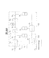
Fig. 1 (prior art) is for showing the schematic diagram of traditional fiber communication system.
Fig. 2 (prior art) has shown the schematic diagram of the optical amplifier apparatus of the optical fiber telecommunications system that is used to utilize Wave division multiplexing.
Fig. 3 shows the view of optical amplifier apparatus according to an embodiment of the invention.
For to show the curve of the operation of the optical amplifier apparatus of Fig. 3 according to an embodiment of the invention, wherein the channel number N in the light signal is changed for Fig. 4 (A) and 4 (B).
Fig. 5 shows the schematic diagram of automatic gain control circuit according to an embodiment of the invention.
Fig. 6 shows the schematic diagram of automatic level control circuit according to an embodiment of the invention.
Fig. 7 shows the schematic diagram of the change-over circuit of the automatic level control circuit shown in Fig. 6 according to an embodiment of the invention.
Fig. 8 and 9 is the schematic diagrames that show automatic level control circuit according to another embodiment of the invention.
Figure 10 shows the view of optical amplifier apparatus according to an embodiment of the invention.
Figure 11 is the view that shows optical amplifier apparatus according to another embodiment of the invention.
Figure 12 is the view that shows optical amplifier apparatus according to an embodiment of the invention.
Figure 13 is the view that shows optical amplifier apparatus according to another embodiment of the invention.
Figure 14 is the view that shows optical amplifier apparatus according to another embodiment of the invention.
Figure 15 is the view that shows optical amplifier apparatus according to another embodiment of the invention.
Figure 16 is the view that shows optical amplifier apparatus according to another embodiment of the invention.
Figure 17 shows according to another embodiment of the invention, to the improvement schematic diagram of the optical amplifier apparatus shown in Figure 16.
Figure 18 (A) has shown the curve of gain relative wavelength characteristic in the rear-earth-doped optical fiber (EDF) in the optical amplifier apparatus according to an embodiment of the invention.
Figure 18 (B) is the curve that shows the transmissivity of the optical fiber in the optical amplifier apparatus according to an embodiment of the invention.
Figure 18 (C) has shown the curve of the overall gain of rear-earth-doped optical fiber (EDF) among Figure 18 (A) according to an embodiment of the invention and optical fiber among Figure 18 (B).
Figure 19 is the view that shows the optical amplifier apparatus of root device embodiments of the invention.
Figure 20 is the view that shows optical amplifier apparatus according to another embodiment of the invention.
Figure 21 is the view that shows optical amplifier apparatus according to another embodiment of the invention.
Figure 22 is the view that shows optical amplifier apparatus according to another embodiment of the invention.
Figure 23 is the view that shows optical amplifier apparatus according to an embodiment of the invention.
Figure 24 is the more detailed view of the part of the optical amplifier apparatus among Figure 23 according to an embodiment of the invention.
Figure 25 shows to adopt the view of the optical fiber telecommunications system of optical amplifier apparatus according to an embodiment of the invention.
Figure 26 is the more detailed view of the optical amplifier apparatus among Figure 25 according to an embodiment of the invention.
Figure 27 is the view that shows the transmission line that uses a plurality of multiplying arrangements according to an embodiment of the invention.
Figure 28 is the sequential chart that shows according to the operation of optical amplifier apparatus of the present invention.
Figure 29 shows the view of the part of optical communication system according to an embodiment of the invention.
Embodiment
In detail referring to embodiments of the invention, these embodiment are shown in the accompanying drawing below, and wherein identical label is represented identical parts.
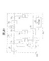
Fig. 2 is the schematic diagram that shows the optical fiber telecommunications system optical amplifier apparatus be used to adopt Wave division multiplexing, and with the U.S. Patent application of quoting here 08/655,027 in unit affinity.
Referring now to Fig. 2,, this optical amplifier apparatus comprises a first 1000 (being sometimes referred to as " rare-earth doped optical fibre amplifier part ") and a second portion 2000 (being sometimes referred to as " automatically controlled electro-optical device part ").
First 1000 comprises a rear-earth-doped optical fiber (BDF) 34, optical branch coupler 36
1With 36
2, optical isolator 38
1With 38
2, optical diode 40
1With 40
2, optical wavelength multiplexing coupler 42, pumping optical diode (LD) 44 and automatic gain of light control circuit (AGC) 46.
The wavelength multiplexing light signal is by optical branch coupler 36
1, optical isolator 38 and optical wavelength multiplexing coupler 42 are sent to rear-earth-doped optical fiber 34.Exciting light beam is provided to rear-earth-doped optical fiber 34 by pumping optical diode 44 by optical wavelength multiplexing coupler 42.The rear-earth-doped optical fiber 34 of wavelength multiplexing optical signals amplifies and passes through optical isolator 38
2With optical branch coupler 36
2Be input to optical attenuator 48.
By optical branch coupler 36
1The part of the wavelength multiplexing light signal of branch is by optical diode 40
1Convert the signal of telecommunication to and be imported into automatic gain of light control circuit 46.By optical branch coupler 36
2The part of the wavelength multiplexing light signal of the amplification of branch is by optical diode 40
2Convert the signal of telecommunication to and be imported into automatic gain of light control circuit 46.Pumping optical diode 44 Be Controlled make the ratio between the level of wavelength multiplexing light signal of the level of input wavelength multiplexing optical signal and amplification remain on a predetermined value.
More particularly, automatically gain of light control circuit 46 control pump laser diodes 44 make it will be by optical diode 40
1Convert to the signal of telecommunication the input wavelength multiplexing optical signal level and by optical diode 40
2The ratio that converts between the level of wavelength multiplexing light signal of amplification of the signal of telecommunication remains a steady state value.Like this, first 1000 keeps wavelength dependency by the gain of light being controlled to be steady state value.
By optical branch coupler 36
3The output wavelength multiplexing optical signal of branch is by optical diode 40
3Be converted into the signal of telecommunication and be imported into automatic level control circuit 50.Optical attenuator 48 is controlled to the wavelength multiplexing light signal is remained steady state value.
More particularly, automatic level control circuit 50 utilizes by optical diode 40
3Control optical attenuator 48 from the signal of telecommunication that the wavelength multiplexing light signal obtains, so that the wavelength multiplexing light signal is remained steady state value.
Unfortunately, when as shown in Figure 2 optical amplifier apparatus was used to utilize the optical fiber telecommunications system of Wave division multiplexing, the variation of the channel number that uses in the light signal of wavelength multiplexing can produce very big problem.
For example,, need amplifier to have predetermined Output optical power usually, so that in receiver, guarantee required signal to noise ratio (S/N) ratio for each wavelength (channel).Supposing has N channel, and the total light output Pc of rare-earth doped optical fibre amplifier that is used to amplify the light signal of wavelength multiplexing is controlled as N*P.Under the situation of the variation of-α, conversion and control is carried out and makes that total optical power is the (P of N ± α) at channel number N existence+α.Since the variation of the luminous power of each concrete wavelength (channel) that conversion and control causes, the decline that may produce nonlinear deterioration or signal to noise ratio (S/N).
In addition, the output of the light of first 1000 is retained as steady state value by second portion 2000 in Fig. 2.Therefore, when the output of first 1000 surpassed predetermined level, second portion 2000 remained steady state value with light output.As a result, the use of optical attenuator 48 will need the extra amplification measure by first 32, and to be used to keep the gain of light be that the pumping optical diode 44 of steady state value should be exponential relationship ground Be Controlled with the level of input wavelength multiplexing optical signal.Therefore, be necessary to provide a relatively high performance pumping optical diode 44.
Fig. 3 shows the view of optical amplifier apparatus according to an embodiment of the invention.This optical amplifier apparatus comprises a first 1000 and second portion 2000.First 1000 comprises a rear-earth-doped optical fiber (EDF) 52
1, optical branch coupler 54
1With 54
2, optical isolator 55
1With 55
2, optical wavelength multiplexing coupler 56
1, optical diode (PD) 58
1With 58
2, pumping optical diode 59
1, automatic gain control circuit (AGC) 60
1The wavelength multiplexing light signal amplifies in first 1000 when keeping wavelength dependency.
For example, the wavelength multiplexing light signal typically is in the frequency band of 1.5 μ m.Erbium doped optic fibre is that this frequency band light signal is amplified in known being used for, and therefore as rear-earth-doped optical fiber (EDF) 52
1In addition, for the wavelength multiplexing light signal in the frequency band that suitably is amplified in the 1.5 μ m that propagate in the erbium doped optic fibre, it is known using the exciting light of 0.98 μ m or 1.48 μ m excitation bands.Therefore, the pumping optical diode 59
1The exciting light of 0.98 μ m or 1.48 μ m excitation bands is provided.
In addition, Fig. 3 has shown the incentive structure of a forward, wherein by pumping optical diode 59
1The exciting light beam that sends passes through rear-earth-doped optical fiber 52 with the direction identical with the wavelength multiplexing light signal
1But, also can adopt the reverse energization structure, wherein laser diode provides one along the direction propagation process rear-earth-doped optical fiber 52 opposite with the wavelength multiplexing light signal
1Exciting light beam.In addition, also can adopt two-way incentive structure, wherein two laser diodes provide along passing rear-earth-doped optical fiber (EDF) 52
1Both direction at rear-earth-doped optical fiber (EDF) 52
1The middle exciting light beam of propagating.Therefore, the not specific type that is limited with to excitation of the present invention.
In addition, when the number of the channel in the wavelength multiplexing light signal was changed, a supervisory signal treatment circuit 70 made the decay of optical attenuator 64 or light transmission keep constant.Therefore, supervisory signal treatment circuit 70 temporarily " freezes " operation of optical attenuator 64.After channel number was changed, supervisory signal treatment circuit 70 allowed the decay of optical attenuators 64, or light transmission is changed, and made the power of wavelength multiplexing light signal remain steady state value according to new channel number.
More particularly, be input to the wavelength multiplexing optical signals optical branch coupler 68 of optical amplifier apparatus
1Branch.The part that is branched is provided to optical diode (PD) 58
4Optical diode (PD) 58
4This component is converted to the signal of telecommunication and this signal of telecommunication is provided to supervisory signal treatment circuit 70.
The control signal of the variation in the number of the channel in the prompting wavelength multiplexing optical transmission system preferably is added to the wavelength multiplexing light signal as a low speed signal by amplitude modulation process.But additive method also can be used to this control signal that superposes.Supervisory signal treatment circuit 70 extracts and discerns this control signal.Supervisory signal treatment circuit 70 is then according to the control signal control optical attenuator 64 or the automatic level control circuit 66 that extract.If the use amplitude modulation(PAM) is by to by optical diode 58
4It is relatively easy that this control signal is extracted in the signal of telecommunication demodulation that obtains.
In addition, also can be sent to supervisory signal treatment circuit 70 by the control channel (wavelength) of a special use.If adopt special-purpose control channel, by an optical branch filter (not shown) from the wavelength multiplexing light signal (by optical branch coupler 68
1Extract) in extract control signal.For example, by being fed to optical diode 58 by the light signal that the optical branch filter extracts
4,, also can extract this and control this signal so that be converted into the signal of telecommunication.
Therefore, by optical branch coupler 68
1The part of the wavelength multiplexing light signal of branch is by optical diode 58
4Be converted into the signal of telecommunication and be fed to supervisory signal treatment circuit 70.When the control signal of prompting channel number variation was extracted and discerns, supervisory signal treatment circuit 70 " freezed " operation of optical attenuator 64.
For the power level of the wavelength multiplexing light signal that guarantees to decay and the number coupling of channel, supervisory signal treatment circuit 70 makes one, and that voltage (reference voltage) is set is selected.So this power level can be controlled as the control level that voltage is set corresponding to this.
In general, there are two methods to be used for monitor monitors signal processing circuit 70 and control optical attenuator 64.In the middle of a method, optical attenuator 64 is directly controlled by supervisory signal treatment circuit 70, shown in the control signal among Fig. 3 69.In another method, optical attenuator 64 is by supervisory signal treatment circuit 70 control indirectly, shown in the control line among Fig. 3 71.
In the prompting (warning) of the number of channel afterwards, in fact the number of channel can increase or reduce.In this case, the control signal finished of the change in the indicating channel number is superimposed on the wavelength multiplexing light signal.Supervisory signal treatment circuit 70 extracts this control signal then.In addition, this control signal can be sent to supervisory signal treatment circuit 70 on Dedicated Control Channel (wavelength).According to the extraction and the identification of control signal, it is the control of steady state value that supervisory signal treatment circuit 70 allows optical attenuators 64 to recover that it is used to keep the power level of wavelength multiplexing light signal.
In addition, change the control signal of finishing except the indicating channel number is provided to supervisory signal treatment circuit 70, this finishing also can be assumed to be through after the preset time.More particularly, after the prompting that channel number changes was presented preset time, the number of channel can be increased or reduce actually.In this case, after the control signal of the prompting that provides the channel number change was extracted and discerned by supervisory signal treatment circuit 70, a timer (not shown) was activated.After preset time, the power level that optical attenuator 64 is driven maintenance wavelength multiplexing light signal once more is a steady state value.
No matter be finishing of the variation that a control signal or preset time cycle is used to the indicating channel number, the information that voltage (reference voltage) according to relevant what channels is increased or removes that is provided with that is used for the power controlling level switches to another level from a level.This information preferably is included in the control signal that is used for pointing out the channel number variation.Therefore, be the control of steady state value by recovering to be used to keep total optical output power, light output is maintained at the steady state value that is complementary with channel number.
Therefore, in response to the change of channel number, optical attenuator 64 is by being frozen in its decay the excessive change that a steady state value has prevented optical output power.At this moment, second portion 2000 is not a steady state value at the power that works in maintenance wavelength multiplexing light signal.After channel number is changed, optical attenuator 64 once more Be Controlled to go to keep the power of wavelength multiplexing light signal be steady state value.Optical attenuator 64 can little by little be driven, and feasible gross output corresponding to channel number is held.Utilize this arrangement, can revise the change in the light output and avoid nonlinear degradation and signal to noise ratio decline.
Fig. 4 (A) and 4 (B) are for showing the curve of the operation of the optical amplifier apparatus of Fig. 3 according to an embodiment of the invention, and wherein for example to be changed from four channels be eight channels to the channel number N in the light signal.Referring now to Fig. 4 (A) and 4 (B),, optical attenuator 64 has a variable light transmission, or decay, and it is by automatic level control circuit 66 and 70 controls of supervisory signal treatment circuit.
In Fig. 4 (A) and 4 (B), when the time, t1 was received, be increased at time t2 channel number in the prompting of the change of channel number.
Before the prompting of the change of channel number is received (promptly before time t1), automatic level control circuit 66 changes the light transmission of automatically controlled variable optical attenuator 64 so that provide a substantially invariable optical signal power at the output of optical attenuator 64.Therefore, before time t1, second portion 2000 is carried out automatic electric-level control (ALC).
When the prompting in the change of channel number is received (at time t1), it is a steady state value that automatic level control circuit 66 keeps the light transmission of automatically controlled variable optical attenuator 64.In this embodiment, the output of optical attenuator 64 can in sightly have one by for example first 1000 or the constant gain that provided by the back level (not shown) of further this signal of amplification.Therefore, after time t1, automatic gain control (AGC), rather than automatic electric-level control (ALC) are performed.
At time t3, after channel number changed, automatic level control circuit 66 changed the light transmission of automatically controlled variable optical attenuator 64 so that provide constant substantially optical signal power at the output of optical attenuator 64.More particularly, after time t3, second portion 2000 is carried out automatic electric-level control (ALC) once more.
As in Fig. 4 (A) and 4 (B) as can be seen, optical attenuator 64 is controlled to provide automatic electric-level control ALC.But when channel number was changed, automatic electric-level control was stopped.On the contrary, when channel number was changed, optical attenuator 64 was controlled to provide a constant light transmission or decay.Between time t1 and t3 in Fig. 4 (A) and 4 (B), when channel number was changed, the operation of optical attenuator 64 can be described to " freezing ".
As mentioned above, between time t1 and t3, the output of optical attenuator 64 has one by for example first 1000, perhaps further amplifies the back grade of constant gain that (not shown) provides of this signal.On the other hand, described in of the present invention additional embodiment detailed description below, second portion 2000 can be modified and make it that a constant gain (rather than automatic electric-level control is provided) can be provided when channel number is changed.In this case, second portion 2000 can comprise the amplifier of a gain controlling so that a constant gain that is used for AGC between time t1 and t3 is provided.
Therefore, shown in Fig. 4 (A) and 4 (B), optical amplifier apparatus comprises an image intensifer (for example first 1000), and it amplifies the light signal with variable channel number.Before or after the number of the channel that changes light signal, controller (for example second portion 2000) is with the light signal of variable light transmission by amplifying, and the power level of the feasible light signal that amplifies is maintained at steady state value substantially according to the channel number in the light signal.In addition, when the channel number in light signal was changed, controller passed through the light signal with the amplification of constant light transmission.
Fig. 5 is for showing that being used to control the gain of light is steady state value automatic gain control circuit 60
1Schematic diagram.Referring now to Fig. 5,, automatic gain control circuit 60
1 Comprise 74, one transistors 76 of 72, one operational amplifiers of a divider and resistance R 1-R6.Vcc is a supply voltage, and Vref is a reference voltage, and G is ground.
As shown in Figure 5, optical diode (PD) 58
1The part of wavelength multiplexing light signal is converted to the signal of telecommunication and is provided to divider 72.Optical diode (PD) 58
2The part of wavelength multiplexing light signal is converted to the signal of telecommunication and is provided to divider 72.Like this, divider 72 has obtained rear-earth-doped optical fiber (EDF) 52
1Input and output between ratio.By pumping optical diode 59
1So but the exciting light beam Be Controlled of emission produces a constant ratio, thereby a constant gain is provided.Automatic gain control circuit 60 in Fig. 5
1Structure just be used for one on the many feasible structure of automatic gain control circuit.
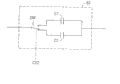
Fig. 6 shows to be used to control the schematic diagram that light is output as the automatic level control circuit 66 of steady state value.Referring now to Fig. 6,, automatic level control circuit 66 comprises resistor R 7-R9, operational amplifier 78, transistor 80, change-over circuit (SWC) 82 and reference voltage circuit 84.Vcc is a supply voltage, and Vref is a reference voltage, and G is ground, and cs1 and the cs2 control signal for providing by supervisory signal treatment circuit 70.Control element 86 is the control element of the optical attenuator 64 of the light transmission that is used to control optical attenuator 64.
For example, if optical attenuator 64 by the magneto-optic corresponding operating, control element 86 can be a coil that is used to apply magnetic field.In addition, for example, if optical attenuator by the photoelectricity corresponding operating, control element 86 can be an electrode, the voltage that wherein is added on the electrode is controlled.Replace optical attenuator 64 if semiconductor optical amplifier is used, but be used to control the bias voltage Be Controlled of the gain of semiconductor optical amplifier.
From the part (see figure 3) of the light signal of optical attenuator 64 output by optical branch coupler 54
3Branch and by optical diode (PD) 58
3Convert the signal of telecommunication to.Then, in Fig. 6, operational amplifier 78 compares the signal of telecommunication with reference voltage (voltage is set) Vref that is provided according to control signal cs1 by reference voltage circuit 84.Difference result relatively is used to driving transistors 80.Be provided to the electric current of control element 86 by control, the decay Be Controlled that is provided by optical attenuator 64 makes light output be maintained at steady state value.
Fig. 7 is for showing the schematic diagram of change-over circuit 82.Referring now to Fig. 7,, change-over circuit 82 comprises capacitor C1 and C2, and they are concrete selections of switch SW of controlled signal CS2 control.Therefore, the frequency characteristic of change-over circuit 82 control automatic level control circuits 66.In addition, change-over circuit 82 is controlled optical attenuator 64 by following the wavelength multiplexing optical signal with predetermined frequency characteristic oxide-semiconductor control transistors 80.Change frequency characteristic from the control signal cs2 of supervisory signal treatment circuit 70 by between the capacitor C1 of change-over circuit 82 and C2, switching.Control signal cs1 switches between the level of different fundamental voltages according to the number of channel.
More particularly, change-over circuit 82 is coupled with operational amplifier 78 (see figure 6)s and resistor R 7 (see figure 6)s and R9 (see figure 6), constitutes a preliminary low-pass filter.The cut-off frequency fc of this preliminary low-pass filter is:
fc=1/2(2πR9.Cswc9)
Wherein Cswc is capacitor C 1 or the C2 that selects.Therefore, by increasing capacitance Cswc, the control circuit shown in Fig. 6 is with lower frequency work.That is, its response is lowered.
Therefore, according to the capacitor C 1 or the C2 of the selection of change-over circuit 82, filter can be changed at the cut-off frequency of high frequency region.
For example, a preferable setting is, the cut-off frequency of the 10-100KHz order of magnitude in normal automatic electric-level control operation, and the decay that is controlled to provide constant at optical attenuator 64 is (for example, thereby when channel is switched, provide constant gain) time, be switched to 0.01Hz.It is desirable to, the control of change-over circuit 82 is little by little carried out, but control gradually needs change-over circuit 82 to be constituted and just be not made of two capacitors by a plurality of capacitors.
Referring to Fig. 6, the cut-off frequency before the prompting of channel-changing is received is high.When the signal of prompting channel number change was received, change-over circuit 82 Be Controlled made cut-off frequency be lowered.Therefore, the decay that is provided by optical attenuator 64 is fixed on a mean value.After channel-changing was finished, change-over circuit 82 Be Controlled made cut-off frequency be converted into height once more.
For example, when supervisory signal treatment circuit 70 extracted and discern the control signal of prompting channel number change, control signal cs2 is provided to change-over circuit 82 made the frequency characteristic of automatic level control circuit 66 be switched to low frequency range.As a result, by optical diode (PD) 58
3The performance of following after the variation in the signal that detects is lowered.That is to say that (for example, the light transmission of optical attenuator 64 keeps constant) temporarily freezed in the constant value control of light output.In addition, control signal cs1 is corresponding to the number that is included in the channel in the light signal, and supervisory signal treatment circuit 70 is provided to reference voltage circuit 84 with control signal cs1.Reference voltage circuit 84 provides a reference voltage V ref corresponding to channel number then.Therefore, gross output is supposed a level that is matched with channel number after channel number changes.For example, reference voltage V ref is changed feasible, when the channel that adds up to α is added to the original channel that adds up to N, and total light output becoming (N+ α) * P.
Refer again to Fig. 6 and Fig. 7, capacitance Cswc can be enough big to freeze the operation of optical attenuator 64.In general, for example, if cut-off frequency fc drops to 0.01Hz from 10KHz, this purpose can be obtained, thereby drops to 10,000-100,00 factor among the cut-off frequency fc.Big like this landing is to be difficult to realize.
That is, the decay that is provided by optical attenuator 64 changes along with variation constantly to provide automatic electric-level control ALC function and compensating polarizing to change.Therefore, the decay of optical attenuator 64 is fixed as certain value (for example when channel number is changed) suddenly may causes problem.On the contrary, decay preferably is maintained at a mean value.
More particularly, Fig. 8 and Fig. 9 are the schematic diagrames that shows automatic level control circuit 66 according to additional embodiments of the invention.Referring now to Fig. 8,, filter 90 is used for constituting by high frequency (fc:-10KHz) and by capacitor and resistor, and is provided in to make between switch 92 and the transistor 80 that the response of automatic electric-level control becomes suitable.For example, the time constant that typically is inferior Millisecond can be changed into the time constant of 10-100 Millisecond.
When cut-off frequency fc was switched to high frequency region, the response of filter accelerated and makes relatively at a high speed variation, and for example polarization variations can be eliminated and the output of optical attenuator 64 is held constant.
More particularly, in Fig. 8, has the voltage of latch cicuit 94 storages of low pass filter (fc:-0.01Hz) corresponding to the average level of the electric current in the control element 86.In ALC operation, the switching that control ring takes place makes that being used for the controlling and driving electric current is that the control ring of steady state value is initialised.That is, when the switching of control ring produces, latched in latch cicuit 94 corresponding to the average level of this electric current, so that as reference voltage.Term " average level " is used, and relies on the variation of time so that keep being input to optical diode (PD) 58 because this bias current has one
3Light beam at a steady state value.More particularly, the voltage that the time of integration that prolongs more that provides by the time constant of utilizing by common control ring, integration obtained is latched in latch cicuit 94.
Fig. 9 is the combination of Fig. 6 and Fig. 8.Referring now to Fig. 9,, capacitor C swc is switched by change-over circuit 82 makes cut-off frequency fc be switched to low frequency range, thereby reduces filter response.Thus, control decays to mean value to latch cicuit 94 according to monitoring value.
More particularly, in Fig. 9, control ring is switched after the time constant that increases common control ring according to control shown in Figure 6, so that reduce the influence that causes in the ALC characteristic that switches in because of control ring.
As mentioned above, supervisory signal treatment circuit 70 can receive control signal be used for it receive be used to provide the prompting that channel number changes after the finishing of reporting channel number of variations.But in addition, when the channel number variation was done, supervisory signal treatment circuit 70 also can not receive control signal.In this case, after being used to provide control signal that channel number changes prompting and being extracted and discerning, a timer (not shown) will be activated.
Be used for after control signal that the reporting channel number of variations finishes is received, or through after the preset time, control signal cs2 turns back to original frequency characteristic with change-over circuit 82.Thus, constant light output control is recovered according to the new reference voltage V ref that is provided with by reference voltage circuit 84.
The control that the light that is used to keep total is output as corresponding to the steady state value of channel number can recover in mode gradually.For example, optical diode (PD) 58
3Output signal can be imported into operational amplifier 78 by time constant circuit 96, perhaps reference voltage V ref can little by little be changed, and is the level corresponding to channel number.
When above-mentioned arrangement guarantees because the frequency characteristic as a result of the control of change-over circuit 82 is switched, the frozen while of constant value control that makes light output, maintenance is by optical diode (PD) 58 in the time of also can work as the control signal that is used to provide the prompting that channel number changes and be extracted and discern
3The signal of output.In this case, maintained value is imported into operational amplifier 78, makes that the constant value control of light output is frozen.Other the arrangement of constant value control that is used to freeze light output also can be used.When the automatically controlled electro-optical device parts of supposition are when being made of optical attenuator 64, can adopt semiconductor optical amplifier to replace optical attenuator 64.Semiconductor optical amplifier should have less wavelength dependency.By the control semiconductor optical amplifier, total light output can be controlled in steady state value.
Figure 10 is for showing the schematic diagram of optical amplifier apparatus according to additional embodiments of the invention.Referring now to Figure 10,, this optical amplifier apparatus comprises a first 1000, second portion 2000 and third part 3000.Third part 3000 comprises a rear-earth-doped optical fiber (EDF) 52
2, an optical branch coupler 54
4, a wavelength multiplexing coupler 56
2, an optical isolator 55
3With 55
4, optical diode (PD) 58
5, pumping optical diode (LD) 59
2With an automatic gain control circuit (AGC) 60
2 Third part 3000 is also shared optical branch coupler 54 with second portion 2000
3And optical diode (PD) 58
3As first 1000, the third part 3000 control gains of light are steady state value.More particularly, second portion 2000 controls are steady state value by the wavelength multiplexing light signal that third part 3000 receives.As a result, the optical output power level of third part 3000 also remains on constant power level.Even when optical signal level during, guarantee to obtain required luminous power total also can provide to amplify by third part 3000 by the decay of the optical attenuator 64 of second portion 2000.
Therefore, the pumping optical diode 59 of first 1000
1Pumping optical diode 59 with third part 3000
2Each can have a relatively little capacity, thereby has reduced cost and the stability that has improved multiplying arrangement.
Although Figure 10 has shown second portion 2000 and third part 3000 and has shared optical branch coupler 54
3And optical diode (PD) 58
3, also can provide independently optical branch coupler and independently optical diode at second portion 2000 and third part 3000.
Automatic gain control circuit 60
1With 60
2Can have identical structure.In addition, the gain of light that has first 1000 and third part 3000 to provide can be identical.In addition, gain also can be according to the characteristic changing of the Transmission Fibers of using in third part 3000.
Under the situation that channel number changes, the optical attenuation that is provided by optical attenuator 64 is directly freezed by supervisory signal treatment circuit 70, and perhaps the supervisory signal treatment circuit 70 by control automatic level control circuit 66 freezes.Similar with the embodiment of Fig. 3, be limited in response to the variation of the light output of the variation of channel number, descend to reduce nonlinear degradation and signal to noise ratio.
Figure 11 is the schematic diagram of optical amplifier apparatus according to another embodiment of the invention.Referring now to Figure 11,, optical amplifier apparatus comprises a first 1000, second portion 2000 and third part 3000, identical with shown in Figure 10.But the optical amplifier apparatus among Figure 11 also comprises automatic electric-level control (ALC) correcting circuit 98, is used to control and proofread and correct the automatic level control circuit 66 of second portion 2000.
More particularly, by the part of the wavelength multiplexing light signal of optical attenuator 64 output by optical branch coupler 54
3Branch is by optical diode (PD) 58
3Convert the signal of telecommunication to and be input to automatic level control circuit 66.Automatic level control circuit 66 control optical attenuators 64 make the gross output of wavelength multiplexing light signal remain on steady state value.But, be not fed to automatic level control circuit 66 in the optical output power of the output wavelength multiplexing optical signal of third part 3000.Therefore, it can not guarantee that the total light output in third part 3000 remains in the predetermined scope.
Accordingly, the part of the output wavelength multiplexing optical signal in third part 3000 is by optical diode (PD) 58
5Be converted into the signal of telecommunication and be input to ALC correcting circuit 98 and automatic gain control circuit 60
2 ALC correcting circuit 98 determines whether total optical output power remains within the preset range.If total optical output power is not within preset range, ALC correcting circuit 98 is controlled automatic level control circuits 66, and automatic level control circuit 66 is controlled optical attenuator 64 conversely total optical output power is remained within the preset range.If semiconductor optical amplifier is used to instead of optical attenuator 64, the gain of automatic level control circuit 66 control semiconductor optical amplifiers makes that the total light output in third part 3000 is maintained in the predetermined scope.
Figure 12 is the schematic diagram of optical amplifier apparatus according to an embodiment of the invention.Image intensifer among Figure 12 is the combination of the multiplying arrangement among Figure 10 and Figure 11.
Referring now to Figure 12,, under the situation that channel number changes, supervisory signal treatment circuit 70 temporarily freezes to be used to control the control that light output is carried out by second portion 2000, makes that the variation in the light output is reduced.In addition, ALC correcting circuit 98 control automatic level control circuits 66 are so that remain on steady state value with the total optical output power in the third part 3000.
Figure 13 is the schematic diagram of optical amplifier apparatus according to an embodiment of the invention.The optical amplifier apparatus of Figure 13 is operated in the similar mode of aforesaid embodiment, and, also comprise an optical branch coupler 54
5, an optical isolator (PD) 58
6, a discrete compensated fiber (DCF) 100 and discrete compensated fiber (DCF) loss correcting circuit 102.Optical branch coupler 54
5And optical isolator (PD) 58
6Can be regarded as being included in the third part 3000.
Discrete compensated fiber 100 is connected between second portion 2000 and the third part 3000.Discrete compensated fiber (DCF) loss correcting circuit 102 control automatic level control circuits 66.In long distance, high power capacity, in the wavelength multiplexing optical transmission system, the discrete compensation relevant with the wavelength multiplexing light signal with the discrete level of Transmission Fibers is necessary.For this reason, discrete compensated fiber 100 is provided.
But, because the insertion that distribution of compensation optical fiber causes loss can have problems.More particularly, the variation of the loss that causes because of distribution of compensation optical fiber can cause the variation of the light output of the repeater that comprises the wavelength multiplexing fiber amplifier.
Therefore, because the loss that discrete compensated fiber 100 causes and automatic level control circuit 66 is set, so that compensate this loss, optical attenuator 64 is controlled to the output that provides constant by measuring.The loss that is caused by discrete compensated fiber 100 is easy to change with the level of discrete compensation.Correspondingly, even carry out constant light output control by automatic level control circuit 66, the level that is input to the wavelength multiplexing light signal of third part 3000 also can change.
Therefore, by the part of the wavelength multiplexing light signal of discrete compensated fiber 100 outputs by optical branch coupler 54
5Branch and by optical isolator (PD) 58
6Convert the signal of telecommunication to.This signal of telecommunication is imported into discrete compensated fiber (DCF) loss correcting circuit 102 and automatic gain control circuit 60
2Whether discrete compensated fiber (DCF) loss correcting circuit 102 is determined by the level of the wavelength multiplexing light signal of discrete compensated fiber 100 outputs within preset range.If this level is in outside the preset range, discrete compensated fiber (DCF) loss correcting circuit 102 provides a correction signal to automatic level control circuit 66.For example, the reference voltage (voltage is set) that is used for the constant control of light output is corrected and makes optical output power be within the preset range.Therefore, the variation of the insertion loss that constitutes in the discrete structure of discrete compensated fiber 100 compensation in Transmission Fibers is corrected, and the predetermined output level of the wavelength multiplexing light signal of amplification is obtained.
Figure 14 is the schematic diagram according to the optical amplifier apparatus of an additional embodiment of the present invention.Referring now to Figure 14,, when 70 extracted and discern a control signal that is used to provide the prompting that channel number changes, the operation of optical attenuator 64 frozen (that is, transmissivity or decay keep constant) made the rapid variation of optical signal level be limited.Discrete compensated fiber (DCF) loss correcting circuit 102 control automatic level control circuits 66 are so that the loss that the level of the discrete compensation that provides according to discrete compensated fiber 100 changes is provided.Therefore, the level that is input to the wavelength multiplexing light signal of third part 3000 is maintained in the preset range.
Figure 15 is for showing the displayed map of optical amplifier apparatus according to a further embodiment of the invention.Referring now to Figure 15,, dispersing in the discrete compensated fiber 100 compensation Transmission Fibers, the loss that the level that discrete compensated fiber (DCF) loss correcting circuit 102 is provided by the compensation that provides according to discrete compensated fiber 100 changes, ALC correcting circuit 98 control automatic level control circuits 66 are so that remain on the level of the output wavelength multiplexing optical signal in the third part 3000 in the preset range.Therefore, the wavelength multiplexing light signal in wavelength multiplexing light optical transmission system is amplified with stable manner, transfer and transmission.
Figure 16 is for showing the schematic diagram of optical amplifier apparatus according to another embodiment of the invention.Referring now to Figure 16,, supervisory signal treatment circuit 70 is according to extracting and discern a control signal that is used to provide the prompting that channel number changes, and control optical attenuator 64 or automatic level control circuit 66 are so that freeze the constant value control of light output.By this way, the quick variation of light output level is limited.
In addition, DCF loss correcting circuit 102 control automatic level control circuits 66 are so that proofread and correct variation in the loss that the discrete level that is provided by discrete compensated fiber 100 is provided.ALC correcting circuit 98 control automatic level control circuits 66 are so that keep output wavelength multiplexing optical signal in the third part 3000 in predetermined scope.
Figure 17 is the improvement of the optical amplifier apparatus shown in Figure 16 according to an embodiment of the invention.More particularly, in Figure 17, optical filter A1 is provided at optical diode (PD) 58
2The optical isolator 55 of input
2Output and optical branch coupler 54
2Between.Optical filter A2 is provided at optical diode (PD) 58
5The optical isolator 55 of input
4Output and optical branch coupler 54
4Between.Disclosed identical in optical filter A1 and A2 and the U.S. Patent application 08/655,027 quoted here, be used for the wavelength dependency of correcting gain.
Figure 18 (A) is the rear-earth-doped optical fiber (EDF) 52 among Figure 17 according to an embodiment of the invention
2Gain and the relation curve between the wavelength characteristic, Figure 18 (B) is the relation curve of the transmissivity relative wavelength of the optical filter A2 among Figure 17, Figure 18 (C) is the rear-earth-doped optical fiber (EDF) 52 among Figure 17
2Overall gain and the curve of optical filter A2.
For example, if rear-earth-doped optical fiber (EDF) 52
2The wavelength that has shown in Figure 18 (A) relies on gain characteristic, and is wherein higher in the gain of long wavelength's scope, at optical diode (PD) 58
5The input provide a gain calibration optical filter A2 to guarantee that amplifier has the smooth gain of a relative wavelength.Provide optical filter A2 to guarantee optical diode (PD) 58
5Receiving the multi-wavelength signals of proofreading and correct makes undesirable sensitivity characteristic (the signal susceptibility is lower and higher in long wavelength's scope in short wavelength range) be corrected.According to rear-earth-doped optical fiber (EDF) 52
1With rear-earth-doped optical fiber (EDF) 52
2Use, also can not provide optical filter A1 and/or A2.
Figure 19 is the schematic diagram of optical amplifier apparatus according to an embodiment of the invention.Referring now to Figure 19,, the position of first 1000 and second portion 2000 has been exchanged.Therefore, control by 2000 pairs of wavelength multiplexing light signals of second portion and to make it have constant power level, make by first's 1000 controls then to have constant gain.
More particularly, the wavelength multiplexing light signal of an input is sent to optical attenuator 64.Pass through optical isolator 55 from the wavelength multiplexing light signal of optical attenuator 64 outputs
1With optical wavelength multiplexing coupler 56
1Be sent to rear-earth-doped optical fiber (EDF) 52
1The wavelength multiplexing light signal that amplifies is by optical isolator 55
2With optical branch coupler 54
2Be output.
By optical branch coupler 54
1The part of the wavelength multiplexing light signal of branch is by optical diode (PD) 58
1Convert the signal of telecommunication to and be fed to automatic level control circuit 66 and automatic gain control circuit 60
1The optical attenuation that automatic level control circuit 66 control optical attenuators 64 provide makes the level of wavelength multiplexing light signal be controlled in the predetermined scope and is sent to first 1000 then.
By optical branch coupler 54
2The part of the wavelength multiplexing light signal of branch is by optical diode (PD) 58
2Convert the signal of telecommunication to and be sent to automatic gain control circuit 60
1Automatic gain control circuit 60
1Control pump laser diode 59
1Make and be input to rear-earth-doped optical fiber (EDF) 52
1With from rear-earth-doped optical fiber (EDF) 52
1Ratio between the level of the wavelength multiplexing light signal of output is maintained at steady state value.
Therefore, even second portion 2000 makes that it is constant that the power level of wavelength multiplexing light signal also is held when the signal by the Transmission Fibers input changes greatly.As a result, the wavelength multiplexing light signal with steady state value is imported into first 1000.Therefore, automatic gain control circuit 60
1Can have a less controlled area and relative simple structure.In addition, owing to be input to rear-earth-doped optical fiber (EDF) 52
1The power level of light signal be prevented from exceeding predetermined level, so there is no need to raise by pumping optical diode 59
1The level of the exciting light beam that provides.That is, the pumping optical diode 59
1Can have less capacity.
Figure 20 is the schematic diagram of optical amplifier apparatus according to additional embodiments of the invention.Similar shown in optical amplifier apparatus shown in Figure 20 and Figure 19 also comprises optical branch coupler 54
3, optical diode (PD) 58
3And supervisory signal treatment circuit 70.
Referring now to Figure 20,, the wavelength multiplexing light signal that provides by Transmission Fibers is imported into optical attenuator 64, and by optical branch coupler 54
3The part of branch is by optical diode (PD) 58
3Convert the signal of telecommunication to and be input to supervisory signal treatment circuit 70.
The control signal that is used to provide the prompting that channel number changes can be superimposed on the wavelength multiplexing light signal or on Dedicated Control Channel by amplitude modulation(PAM) and be transmitted.According to extracting and discern the control signal that this is used to provide the prompting that channel number changes, the optical attenuation that supervisory signal treatment circuit 70 control automatic level control circuits 66 and keeping are provided by optical attenuator 64 makes optical output power no longer remain on steady state value at the currency operation of optical attenuator 64 (thereby freeze).
When channel number changes when finishing, supervisory signal treatment circuit 70 allow optical attenuators 64 to recover it to be used to keep optical output power be the control of steady state value.Utilize this arrangement, can reduce or eliminate the quick variation of the power level in the light signal.
Figure 21 is the schematic diagram according to the optical amplifier apparatus of further embodiment of the present invention.Similar shown in optical amplifier apparatus shown in Figure 21 and Figure 19 just also comprises ALC correcting circuit 98.
Figure 22 is the schematic diagram according to the optical amplifier apparatus of further embodiment of the present invention.Optical amplifier apparatus shown in Figure 22 is the combination of the optical amplifier apparatus shown in Figure 20 and 21.
Referring now to Figure 22,, ALC correcting circuit 98 control automatic level control circuits 66 make the power level of output wavelength multiplexing optical signal be in the preset range.According to extracting and discern the control signal that this is used to provide the prompting that channel number changes, supervisory signal treatment circuit 70 freezes to control automatic level control function makes optical output power no longer remain on steady state value.
Figure 23 is the schematic diagram of optical amplifier apparatus according to an embodiment of the invention.Referring now to Figure 23,, when channel number is changed, be not to control (freezing) optical attenuator 64, but image intensifer is changed to agc mode as an integral body when channel number changes so that a constant decay is provided.This change can be that steady state value is obtained by the ratio of input and output of control optical attenuator 64.It is steady state value that this operation is equivalent to keep the gain G (0≤G≤1) of optical attenuator 64 or the light transmission of optical attenuator 64.
Therefore, in Figure 23, switch 104 is by 70 controls of supervisory signal treatment circuit, in the automatic electric-level control that is provided by automatic level control circuit 66 with by automatic gain control 60
3Switch between the automatic gain control that provides.More particularly, for example, shown in Fig. 4 (A), supervisory signal treatment circuit 70 makes switch 104 before channel variation and select automatic level control circuit 66 afterwards.When channel number was changed, supervisory signal treatment circuit 70 made switch 104 select automatic gain control 60
3
Figure 23 also shows a laser diode (LD) 105, it by supervisory signal treatment circuit 70 control downstream the light parts for example the downstream optical repeater send information.For example, as following described in detail, laser diode (LD) 105 can be monitored signal processing circuit 70 and use with the information of light parts transmission downstream.
Figure 24 is the more detailed view of the optical amplifier apparatus among Figure 23.Referring now to Figure 24,, its operation is as follows:
(1) common (that is, when channel number is not changed), switch 104 automatic level control circuits 66 make the optical output power level of optical attenuator 64 be monitored and be maintained at steady state value.
(2) when supervisory signal treatment circuit 70 receives the cue of channel number change, automatic gain control 60
3Gain supervisory signal 107 be read out, make that the average gain (decay) with respect to the time constant of 10-100ms level is determined.
(3) corresponding to the reference voltage V of the average gain of in (2), determining
AGCBe output to automatic gain control 60 from supervisory signal treatment circuit 70
3
(4) switch 104 is selected automatic gain control 60 then
3
(5) supervisory signal treatment circuit 70 receives the information that indication is included in the new number of the channel in the wavelength multiplexing light signal.
(6) supervisory signal treatment circuit 70 provides a benchmark electricity V corresponding to the new number of channel to automatic level control circuit 66
AGC.
(7) supervisory signal treatment circuit 70 receives the signal that the indicating channel number of variations is finished.Perhaps, the receiving key of the signal that changes from the prompting channel number is through predetermined a period of time.
(8) switch 104 is selected automatic level control circuit 66.
Relation between the drive current of decay that is provided by optical attenuator 64 and the control element 86 that provided by transistor 80 can be depending on certain parameter, working temperature for example, but generally be man-to-man relation.Therefore, (2) can be substituted by a process, thereby drive current is monitored (with respect to the time constant with respect to the 10-100ms level), so that determine average gain (decay) according to the drive current that monitors.But the drive current Be Controlled makes its average level be held constant.
Figure 25 is for adopting the schematic diagram according to the optical fiber telecommunications system of optical amplifier apparatus of the present invention.Referring now to Figure 25,, transmitter (Tx) 108 and send a SV light beam to receiver (Rx) 110, wherein the SV light beam is the light with the main signal wavelength multiplexing.Main signal is used to send downstream information.Image intensifer (O-AMP) 112 amplifies the SV light beam.Main signal control 114 and supervisory signal are handled 116 and are performed.
Figure 26 is the more detailed schematic diagram of optical amplifier apparatus, and it comprises the image intensifer 112 among Figure 25, and main signal control 114 and supervisory signal handle 116.The optical amplifier apparatus of Figure 26 is similar to the optical amplifier apparatus among Fig. 3, but comprises that a laser diode (LD) 105 is used for sending downstream the SV light beam.
More particularly, supervisory signal treatment circuit 70 inserts indication in the SV light beam will be held constant when the decay or the light transmission of optical attenuator 64, or the information of " frozen ".The SV light beam that is loaded with this information is sent to transmission line by laser diode (LD) 105.
Figure 27 is the schematic diagram that shows the transmission line that utilizes a plurality of optical amplifier apparatus according to an embodiment of the invention.Referring now to Figure 27,, the wavelength multiplexing optical communication system comprises transmitter Tx120, wavelength multiplexing fiber amplifier/repeater OAMP 122 and receiver Rx 124.When channel number changes when processed, all OAMP 122 in the circuit of the upstream in system (or downstream) are set to the constant light gain controlling.
The amplifier (not shown) also is set to constant-gain control with the wavelength multiplexing light prime amplifier (not shown) that can be provided among each receiver Rx 124 behind the wavelength multiplexing light that can provide in each transmitter Tx 120.When all OAMP 122 were in the constant-gain state of a control, the light signal that is fed to the light receiving element among the receiver Rx 124 can be changed.In the transmission line with the optical amplifier apparatus shown in Figure 25-27, the decay of all fiber amplifiers in the path that can determine whether to be managed by the receiving terminal on the transmission line (Rx) is fixed and the gain of light remains on steady state value.Remain on steady state value in case determine the gain of light of all fiber amplifiers, the information of indication identical content is sent to transmission ends (Tx) by a path backward, thereby the variation of channel number can be begun.
Be the example that shown in Figure 25-27, has the operating process in the transmission line of optical amplifier apparatus below, be used for the variation of processing channel number.
(1) signal that changes of prompting channel number is by from upstream SV transmitting terminal (SVTx).
(2) the supervisory signal treatment circuit 70 of each OAMP receives the signal that the prompting channel number changes.
(3) each OAMP begins the operation of " freezing " relevant optical attenuator.
(4) each OAMP finish relevant optical attenuator freeze operate and send the downstream information that the constant gain of light of indication control begun (identifier that is used to discern concrete OAMP also is inserted in supervisory signal) by this information of carrying on supervisory signal.
(5) upstream SV receiving terminal (SVRx) confirms that all upstream OAMP are in the constant light gain-state.
(6) downstream SV transmitting terminal (SVTx) announces that all upstream OAMP are in the constant light gain-state.
(7) downstream SV receiving terminal (SVRx) confirms that all upstream OAMP are in the constant light gain-state.
(8) the actual channel number that changes of upstream transmitting terminal (Tx).
(9) upstream SV transmitting terminal (SVTx) sends the information that the variation of indicating channel number is done.
(10) the supervisory signal treatment circuit in each OAMP 70 receives the information that the variation of index signal numbers is done.
(11) each OAMP cancellation is used to the freezing operation and proceed to constant light output control of operation of the optical attenuator that freezes to be correlated with.
(12) each OAMP sends the downstream information (identification signal of discerning concrete OAMP also is issued) that indication has been finished to the conversion of constant light output control with the form of supervisory signal.
(13) upstream SV receiving terminal (SVRx) receive all OAMP of indication treated the information that changes of channel number.
(14) indicate all OAMP treated the information that changes of channel number be sent to transmitting terminal.
Figure 28 is the sequential chart that shows the aforesaid operations flow process.Therefore, in the processing procedure of the variation of channel number, the wavelength multiplexing fiber amplifier is temporarily stopped from carrying out automatic level control function, and, carry out the constant-gain controlled function on the contrary, perhaps make optical amplifier apparatus, on the whole, carry out the constant-gain function.
But in optical communication system, the power that is necessary to keep to be provided to the light signal of light receiving element usually is steady state value.Although take place under regular situation because the variation of the input power that polarization variations causes, the gain of light that is used to keep fiber amplifier is that the control of steady state value makes the power of the light signal that is provided to light receiving element change.
This problem can be by being channel independently with the light signal demultiplexing, and the power level of controlling the channel of each demultiplexing overcomes.
More particularly, Figure 29 is a schematic diagram that shows the part of optical communication system according to an embodiment of the invention.Referring now to Figure 29,, demultiplexer (DEMUX) 125 is channel independently with wavelength multiplexing light signal demultiplexing, is received by receiver 126 independently.Light prime amplifier 127 and automatic electric-level control unit 128 are provided for each channel, make relevant receiver 126 receive the light signal of constant power level.
According to the abovementioned embodiments of the present invention, optical attenuator or image intensifer can Be Controlled, and constant gain is provided when the channel number in the wavelength multiplexing light signal is changed.Like this, gain G can be in scope (0≤G≤1).Therefore, but the optical attenuator Be Controlled, and the ratio of the input and output by keeping optical attenuator provides constant gain for steady state value.
According to the abovementioned embodiments of the present invention, dopant is erbium (Er) in the rear-earth-doped optical fiber that uses in image intensifer.But the present invention is not limited to erbium doped optic fibre.On the contrary, other rare-earth doped optical fibres, for example neodymium (Nd) doped fiber or praseodymium (Pr) doped fiber, the wavelength according to related also may be utilized.In addition, for example, various optical diodes disclosed herein can be substituted by optotransistor.
Concrete automatic gain control circuit and automatic level control circuit are disclosed according to the abovementioned embodiments of the present invention.But the present invention is not limited to these specific circuit structures, or other circuit structure disclosed herein.The opposite different circuit structure that also can adopt other.
In addition, according to the abovementioned embodiments of the present invention, optical attenuator is used to the decay that provides variable.The optical attenuator that many different known types are arranged, the present invention is not limited to the optical attenuator of any specific type.
Although foregoing description most preferred embodiments more of the present invention it will be understood by those of skill in the art that and can make many changes and not break away from accompanying Claim book or equivalent institute restricted portion these embodiment.
Claims (4)
1, a kind of wavelength multiplexing optics transmitting system comprises:
Optical device is used for sending wavelength multiplexing light signal and control light signal to optical transmission path, and this wavelength multiplexing light signal has and the corresponding a plurality of channels of the light signal with different wavelength, and this control light signal is used for the change of the number of notification channel; And
The optics multiplying arrangement comprises: optical amplification device is used to receive through this wavelength multiplexing light signal of described optical transmission path transmission and to it and amplifies; Receiving system is used to receive this control light signal that sends through described optical transmission path; And gain control, be used for the detection of the change of this channel number of described control light signal being notified in response to described receiving system, make it to keep constant thereby the gain of described optical amplification device controlled.
2, a kind of wavelength multiplexing optics transmitting system comprises:
Optical device is used for sending the wavelength multiplexing light signal to optical transmission path, and this wavelength multiplexing light signal has and the corresponding a plurality of channels of the light signal with different wavelength, and the control light signal of finishing of the change of the number of notification channel; And
Optical amplification device is used for this wavelength multiplexing light signal that sends through described optical transmission path is amplified; And receiving system is used to receive this control light signal that sends through described optical transmission path; And
Level controller, be used for the detection of the change of this channel number of described control light signal being notified in response to described receiving system, described amplifying device amplified and the level of this wavelength multiplexing light signal of output has predetermined value thereby described optical amplification device controlled.
3, a kind of optical wavelength multiplex communication system comprises:
Optical terminal equipment comprises: be used for sending to optical transmission path the device of optical wavelength multiplexed signals, this optical wavelength multiplexed signals comprises the light signal with different reuse wavelengths; And, be used for the device of output control signal when the number of the wavelength of these light signals that are included in this optical wavelength multiplexed signals changes; And
The optics multiplying arrangement, it comprises: optical amplification device is used for receiving this optical wavelength multiplexed signals through described optical transmission path and it being amplified; And gain control is used to survey this control signal and the gain of described optical amplification device is controlled to make it keeping constant.
4, a kind of optical wavelength multiplex communication system comprises:
Optical terminal equipment comprises: be used for sending to optical transmission path the device of optical wavelength multiplexed signals, this optical wavelength multiplexed signals comprises the light signal with different reuse wavelengths; And, be used for when the number of the wavelength of these light signals that are included in this optical wavelength multiplexed signals changes, exporting first control signal and after the described change of this number of wavelength, export the device of second control signal; And
The optics multiplying arrangement comprises: optical amplification device is used for receiving this optical multiplexer signal and it being amplified through described optical transmission path; Gain control is used for when detecting this first control signal the gain of described optical amplification device being controlled to make it keeping constant; And level controller is used for when detecting this second control signal the level of this optical wavelength multiplexed signals that described optical amplification device amplified being controlled so that this level has the device of predetermined value.
Applications Claiming Priority (3)
| Application Number | Priority Date | Filing Date | Title |
|---|---|---|---|
| JP11144796 | 1996-05-02 | ||
| JP111447/1996 | 1996-05-02 | ||
| JP111447/96 | 1996-05-02 |
Related Parent Applications (1)
| Application Number | Title | Priority Date | Filing Date |
|---|---|---|---|
| CN97110838A Division CN1121626C (en) | 1996-05-02 | 1997-04-30 | Controller for controlling light-changable attenuator |
Publications (2)
| Publication Number | Publication Date |
|---|---|
| CN1406018A CN1406018A (en) | 2003-03-26 |
| CN100477572C true CN100477572C (en) | 2009-04-08 |
Family
ID=14561441
Family Applications (5)
| Application Number | Title | Priority Date | Filing Date |
|---|---|---|---|
| CNB021232466A Expired - Lifetime CN100477563C (en) | 1996-05-02 | 1997-04-30 | Controller for controlling changeable light attenuator |
| CNB021232482A Expired - Lifetime CN100477573C (en) | 1996-05-02 | 1997-04-30 | Controller for controlling changeable light attenuator |
| CN97110838A Expired - Lifetime CN1121626C (en) | 1996-05-02 | 1997-04-30 | Controller for controlling light-changable attenuator |
| CNB021232474A Expired - Lifetime CN100477572C (en) | 1996-05-02 | 1997-04-30 | Controller for controlling changeable light attenuator |
| CNB021232458A Expired - Lifetime CN100477571C (en) | 1996-05-02 | 1997-04-30 | Controller for controlling changeable light attenuator |
Family Applications Before (3)
| Application Number | Title | Priority Date | Filing Date |
|---|---|---|---|
| CNB021232466A Expired - Lifetime CN100477563C (en) | 1996-05-02 | 1997-04-30 | Controller for controlling changeable light attenuator |
| CNB021232482A Expired - Lifetime CN100477573C (en) | 1996-05-02 | 1997-04-30 | Controller for controlling changeable light attenuator |
| CN97110838A Expired - Lifetime CN1121626C (en) | 1996-05-02 | 1997-04-30 | Controller for controlling light-changable attenuator |
Family Applications After (1)
| Application Number | Title | Priority Date | Filing Date |
|---|---|---|---|
| CNB021232458A Expired - Lifetime CN100477571C (en) | 1996-05-02 | 1997-04-30 | Controller for controlling changeable light attenuator |
Country Status (6)
| Country | Link |
|---|---|
| US (14) | US6025947A (en) |
| EP (6) | EP0805571B1 (en) |
| JP (1) | JP2000196534A (en) |
| KR (5) | KR100289013B1 (en) |
| CN (5) | CN100477563C (en) |
| DE (4) | DE69737813T2 (en) |
Families Citing this family (195)
| Publication number | Priority date | Publication date | Assignee | Title |
|---|---|---|---|---|
| JP3306693B2 (en) * | 1995-01-19 | 2002-07-24 | 富士通株式会社 | Optical amplifier, optical wavelength division multiplexing communication system, optical terminal equipment and optical repeater |
| JP2000077757A (en) * | 1998-08-28 | 2000-03-14 | Hitachi Ltd | Optical amplifier, optical transmission device and system thereof |
| US6025947A (en) | 1996-05-02 | 2000-02-15 | Fujitsu Limited | Controller which controls a variable optical attenuator to control the power level of a wavelength-multiplexed optical signal when the number of channels are varied |
| US6369938B1 (en) | 1996-05-28 | 2002-04-09 | Fujitsu Limited | Multi-wavelength light amplifier |
| GB2314714B (en) * | 1996-06-26 | 2000-04-05 | Northern Telecom Ltd | Optical amplifier modules |
| JP3821920B2 (en) * | 1996-09-17 | 2006-09-13 | 富士通株式会社 | Optical communication system |
| JP2914334B2 (en) * | 1997-01-20 | 1999-06-28 | 日本電気株式会社 | Optical amplifier output level control method for WDM communication system |
| JP3542253B2 (en) * | 1997-06-19 | 2004-07-14 | 株式会社日立コミュニケーションテクノロジー | Optical fiber amplifier and optical transmission system using the same |
| US6078418A (en) * | 1997-08-12 | 2000-06-20 | Lucent Technologies Inc. | Wavelength locking of variable dispersive elements |
| JPH11122192A (en) * | 1997-10-17 | 1999-04-30 | Fujitsu Ltd | Optical amplifier and optical communication system provided with the same |
| JP3050299B2 (en) * | 1997-11-17 | 2000-06-12 | 日本電気株式会社 | WDM transmission equipment |
| JP3829962B2 (en) * | 1998-01-22 | 2006-10-04 | 富士通株式会社 | Optical attenuator, system including the optical attenuator, optical amplifier, and terminal device |
| KR19990069330A (en) * | 1998-02-06 | 1999-09-06 | 윤종용 | Optical amplifier with constant output power per channel and its method |
| JP4005646B2 (en) * | 1998-02-06 | 2007-11-07 | 富士通株式会社 | Optical amplifier and excitation light source control method in optical amplifier |
| US5966493A (en) * | 1998-02-20 | 1999-10-12 | Molecular Optoelectronics Corporation | Fiber optic attenuators and attenuation systems |
| US6441955B1 (en) | 1998-02-27 | 2002-08-27 | Fujitsu Limited | Light wavelength-multiplexing systems |
| US6496300B2 (en) * | 1998-02-27 | 2002-12-17 | Fujitsu Limited | Optical amplifier |
| US6317233B1 (en) * | 1998-03-04 | 2001-11-13 | Lg Electronics Inc. | Optical power equalizer in WDM optical communication system and variable attenuator for use therein |
| US6603596B2 (en) | 1998-03-19 | 2003-08-05 | Fujitsu Limited | Gain and signal level adjustments of cascaded optical amplifiers |
| US6061171A (en) * | 1998-05-22 | 2000-05-09 | Ciena Corporation | Optical amplifier having a variable attenuator controlled based on input power |
| US6057959A (en) * | 1998-05-22 | 2000-05-02 | Ciena Corporation | Optical amplifier having substantially uniform spectral gain |
| US6532103B1 (en) * | 1998-06-17 | 2003-03-11 | Hitachi, Ltd. | Optical fiber amplifier and optical transmission system using the same |
| JP4056133B2 (en) * | 1998-07-06 | 2008-03-05 | 富士通株式会社 | Optical amplifier |
| EP0981212A1 (en) * | 1998-08-14 | 2000-02-23 | Telefonaktiebolaget Lm Ericsson | Path monitoring in optical communication systems |
| DE19838788A1 (en) * | 1998-08-26 | 2000-03-09 | Siemens Ag | Controlled optical amplifier |
| JP3134854B2 (en) * | 1998-09-07 | 2001-02-13 | 日本電気株式会社 | Optical amplifier |
| WO2000021166A1 (en) * | 1998-10-04 | 2000-04-13 | The Furukawa Electric Co., Ltd. | Optical amplifier |
| KR100316308B1 (en) * | 1998-10-07 | 2002-02-19 | 윤종용 | WDM-EDFA of constant output power per channel |
| KR100416439B1 (en) * | 1998-11-24 | 2004-03-30 | 삼성전자주식회사 | Fiber Amplifiers Controlling Gain Flatness |
| KR100283956B1 (en) * | 1998-11-24 | 2001-04-02 | 윤종용 | Fiber amplifier with constant output strength for each channel and its amplification method |
| US6163399A (en) * | 1998-12-08 | 2000-12-19 | Nortel Networks Limited | Method and apparatus for suppressing transients in optical amplifiers |
| US6721508B1 (en) * | 1998-12-14 | 2004-04-13 | Tellabs Operations Inc. | Optical line terminal arrangement, apparatus and methods |
| JP3782908B2 (en) * | 1998-12-18 | 2006-06-07 | 富士通株式会社 | Control method of optical wavelength division multiplexing transmission apparatus |
| JP3851007B2 (en) * | 1998-12-18 | 2006-11-29 | 富士通株式会社 | Wavelength multiplexed light detector |
| JP3802992B2 (en) * | 1999-02-08 | 2006-08-02 | 富士通株式会社 | WDM optical communication system |
| JP2000299518A (en) * | 1999-02-10 | 2000-10-24 | Oki Electric Ind Co Ltd | Optical fiber amplifier and control thereof |
| US6205273B1 (en) * | 1999-03-02 | 2001-03-20 | Lucent Technologies Inc. | Waveguide grating router having a predetermined composite amplitude spectrum |
| GB2347809B (en) * | 1999-03-12 | 2001-06-20 | Marconi Comm Ltd | Signal transmission system |
| JP2000269578A (en) * | 1999-03-18 | 2000-09-29 | Fujitsu Ltd | Method and device for light amplification and its system |
| JP3670156B2 (en) * | 1999-03-18 | 2005-07-13 | 富士通株式会社 | Method, apparatus and system for transmitting a supervisory light signal |
| US6215584B1 (en) * | 1999-05-10 | 2001-04-10 | Jds Uniphase Inc. | Input independent tilt free actively gain flattened broadband amplifier |
| JP3903650B2 (en) * | 1999-06-18 | 2007-04-11 | 住友電気工業株式会社 | Optical amplifier and optical amplifier control method |
| GB2363014B (en) * | 1999-06-30 | 2002-02-13 | Marconi Comm Ltd | Optical System |
| KR100334789B1 (en) * | 1999-07-22 | 2002-05-02 | 윤종용 | Wide band light source for testing optic elements using feedback loop |
| US7170673B2 (en) | 1999-07-30 | 2007-01-30 | Mitsubishi Denki Kabushiki Kaisha | Optical amplifying repeater apparatus and optical amplifying/repeating transmission system |
| EP1120925B1 (en) * | 1999-07-30 | 2007-10-17 | Mitsubishi Denki Kabushiki Kaisha | Optical amplification repeater and optical amplification repeating and transmitting system |
| US6366393B1 (en) * | 1999-08-25 | 2002-04-02 | Lucent Technologies Inc. | Fast gain control for optical amplifiers |
| US6411429B1 (en) * | 1999-10-19 | 2002-06-25 | Fujitsu Limited | Optical amplifying apparatus, wide-band optical amplifying apparatus, and optical communication system |
| JP2001168426A (en) * | 1999-12-10 | 2001-06-22 | Nec Corp | Block gain equalizer |
| EP1128504B8 (en) * | 2000-02-23 | 2009-08-12 | Fujitsu Limited | Optical amplifier |
| US6563628B2 (en) * | 2000-02-25 | 2003-05-13 | Fujikura Ltd. | Gain tilt free optical fiber amplifier in a wide dynamic gain range |
| JP3588435B2 (en) * | 2000-02-28 | 2004-11-10 | 富士通株式会社 | Optical amplification device, composite optical amplification device, and optical communication system |
| US6634807B1 (en) | 2000-03-14 | 2003-10-21 | Lucent Technologies Inc. | Optical transmission system including performance optimization |
| GB2360602B (en) * | 2000-03-23 | 2002-05-01 | Marconi Comm Ltd | Optical attenuator including dual control loops |
| IL136177A (en) * | 2000-05-16 | 2005-09-25 | Eci Telecom Ltd | Optical transponder and automatic optical signal type identification method for use therewith |
| US6885683B1 (en) | 2000-05-23 | 2005-04-26 | Imra America, Inc. | Modular, high energy, widely-tunable ultrafast fiber source |
| JP2001358392A (en) * | 2000-06-13 | 2001-12-26 | Oki Electric Ind Co Ltd | Safe light transition control method and optical fiber amplifier |
| JP2001356075A (en) | 2000-06-15 | 2001-12-26 | Advantest Corp | Light characteristic measuring apparatus and method and recording medium |
| JP2002050816A (en) * | 2000-08-02 | 2002-02-15 | Fujitsu Ltd | Optical amplifier |
| KR100346221B1 (en) * | 2000-09-06 | 2002-08-01 | 삼성전자 주식회사 | Gain control device and method thereof for a erbium doped fiber amplifier |
| GB2366925A (en) * | 2000-09-13 | 2002-03-20 | Marconi Comm Ltd | Power control and equalisation in an optical WDM system |
| US6377396B1 (en) * | 2000-09-26 | 2002-04-23 | Onetta, Inc. | Optical amplifiers with variable optical attenuation for use in fiber-optic communications systems |
| US6782199B1 (en) | 2000-09-29 | 2004-08-24 | Onetta, Inc. | Optical communications systems with optical subsystem communications links |
| US6414788B1 (en) * | 2000-10-02 | 2002-07-02 | Onetta, Inc. | Optical amplifier system with transient control |
| US6900931B1 (en) * | 2000-10-02 | 2005-05-31 | Ciena Corporation | Three-stage optical amplifier having flat spectral gain |
| US6424457B1 (en) | 2000-10-06 | 2002-07-23 | Onetta, Inc. | Optical amplifiers and methods for manufacturing optical amplifiers |
| US6417961B1 (en) | 2000-10-10 | 2002-07-09 | Onetta, Inc. | Optical amplifiers with dispersion compensation |
| US6341034B1 (en) * | 2000-10-18 | 2002-01-22 | Onetta Inc. | Optical amplifier system with transient control using spectrally filtered input |
| US6498677B1 (en) * | 2000-10-23 | 2002-12-24 | Onetta, Inc. | Optical amplifier systems with transient control |
| US6441950B1 (en) | 2000-11-03 | 2002-08-27 | Onetta, Inc. | Distributed raman amplifier systems with transient control |
| US6542287B1 (en) | 2000-12-12 | 2003-04-01 | Onetta, Inc. | Optical amplifier systems with transient control |
| US6621625B1 (en) * | 2000-12-13 | 2003-09-16 | Avanex Corporation | Optical node including three-stage optical amplifier with automatic gain and level control |
| KR100358115B1 (en) * | 2000-12-14 | 2002-10-25 | 한국전자통신연구원 | Dynamic gain-controlled erbium-doped fiber amplifier |
| US6396623B1 (en) | 2000-12-19 | 2002-05-28 | Onetta, Inc. | Wide-band optical amplifiers with interleaved gain stages |
| JP2002198911A (en) * | 2000-12-25 | 2002-07-12 | Nec Corp | Means of optical level automatic controle and optical signal receiving system equipped with its |
| US6333798B1 (en) * | 2001-02-13 | 2001-12-25 | Seneca Networks, Inc. | Bidirectional WDM optical communication network |
| US6633430B1 (en) * | 2001-02-15 | 2003-10-14 | Onetta, Inc. | Booster amplifier with spectral control for optical communications systems |
| US6417965B1 (en) | 2001-02-16 | 2002-07-09 | Onetta, Inc. | Optical amplifier control system |
| US6522459B1 (en) | 2001-02-22 | 2003-02-18 | Onetta, Inc. | Temperature control and monitoring of optical detector components in an optical communication system |
| KR100387072B1 (en) * | 2001-02-23 | 2003-06-12 | 삼성전자주식회사 | Bidirectional Optical Amplifier |
| US6476961B1 (en) | 2001-04-26 | 2002-11-05 | Onetta, Inc. | Optical amplifier systems with transient control |
| US6690506B2 (en) | 2001-05-17 | 2004-02-10 | Corning Incorporated | Control architecture and method for optical amplifiers |
| US6943937B2 (en) * | 2001-05-17 | 2005-09-13 | Avanex Corporation | Optical amplifier performance controller and method of use |
| US20020186458A1 (en) * | 2001-06-08 | 2002-12-12 | Photon-X, Inc. | Dynamically controlled optical amplifier module |
| US6556345B1 (en) | 2001-06-21 | 2003-04-29 | Onetta, Inc. | Optical network equipment with control and data paths |
| US6687049B1 (en) | 2001-07-03 | 2004-02-03 | Onetta, Inc. | Optical amplifiers with stable output power under low input power conditions |
| KR100416975B1 (en) * | 2001-07-10 | 2004-02-05 | 삼성전자주식회사 | Auto gain control device of a fiber amplifier |
| US6989923B2 (en) | 2001-08-08 | 2006-01-24 | Photuris, Inc. | Optical amplifier having automatic gain control with improved performance |
| US20030030861A1 (en) * | 2001-08-13 | 2003-02-13 | John Mellert | Methods for reliable communication of link monitoring information in optical communications networks |
| US20030030860A1 (en) * | 2001-08-13 | 2003-02-13 | John Mellert | Redundant line unit monitoring architecture |
| US6757099B2 (en) | 2001-08-15 | 2004-06-29 | Pts Corporation | Optical power transient control scheme for EDFA amplifiers |
| US6577789B1 (en) | 2001-09-26 | 2003-06-10 | Onetta, Inc. | Double-pass optical amplifiers and optical network equipment |
| US6690505B1 (en) | 2001-09-28 | 2004-02-10 | Onetta, Inc. | Optical network equipment with gain transient control and automatic drift compensation |
| US20030067670A1 (en) * | 2001-10-04 | 2003-04-10 | Lacra Pavel | Dynamic optical spectral control scheme for optical amplifier sites |
| GB0124258D0 (en) * | 2001-10-09 | 2001-11-28 | Marconi Comm Ltd | Optical amplifier control in WDM communications systems |
| US6697397B2 (en) | 2001-11-15 | 2004-02-24 | Alcatel | Wavelength compensated ALC loop |
| JP3799266B2 (en) * | 2001-11-15 | 2006-07-19 | 富士通株式会社 | Noise light removal method, noise light removal apparatus and optical transmission system using stimulated Brillouin scattering |
| JP3923301B2 (en) * | 2001-11-29 | 2007-05-30 | 富士通株式会社 | Optical amplifier supervisory control method in WDM communication system |
| JP4481540B2 (en) * | 2001-12-07 | 2010-06-16 | 富士通株式会社 | Optical amplifier |
| US20040208545A1 (en) * | 2001-12-13 | 2004-10-21 | Ali Langari | Optical switch with enhanced flexibility |
| JP3986824B2 (en) * | 2001-12-28 | 2007-10-03 | 富士通株式会社 | Optical filter control method, control device, and optical node device |
| JP4128356B2 (en) * | 2001-12-28 | 2008-07-30 | 富士通株式会社 | Control device for optical device |
| JP3848327B2 (en) * | 2002-03-28 | 2006-11-22 | 富士通株式会社 | Optical device having loss compensation function and optical amplifier for loss compensation |
| FR2838190B1 (en) | 2002-04-08 | 2004-10-15 | Cit Alcatel | DEVICE FOR DYNAMIC MEASUREMENT AND / OR CONTROL OF POWER LOSS IN AN OPTICAL TRANSMISSION LINE WITH SUPERVISORY CHANNEL, AND ASSOCIATED PROCESS |
| US7153362B2 (en) * | 2002-04-30 | 2006-12-26 | Samsung Electronics Co., Ltd. | System and method for real time deposition process control based on resulting product detection |
| JP4152125B2 (en) * | 2002-05-30 | 2008-09-17 | 富士通株式会社 | Optical signal level control device |
| US6977770B2 (en) * | 2002-06-14 | 2005-12-20 | Fujitsu Limited | Optical amplifier and control method therefor |
| DE60311813T2 (en) * | 2002-07-11 | 2007-12-06 | Koninklijke Philips Electronics N.V. | OPTICAL RECEIVER SWITCHING |
| DE10231333A1 (en) * | 2002-07-11 | 2004-01-22 | Bayer Cropscience Ag | Cis-alkoxy-substituted 1-H-pyrrolidine-2,4-dione spirocyclic derivatives |
| ATE341868T1 (en) * | 2002-07-22 | 2006-10-15 | Cit Alcatel | SETTING OF OPTICAL CHARACTERISTICS IN WAVELENGTH MULTIPLEX SYSTEMS |
| US20040126119A1 (en) * | 2002-08-20 | 2004-07-01 | Evangelides Stephen G. | Method and apparatus for providing a terminal independent interface between a terrestrial optical terminal and an undersea optical transmission path |
| US20040096215A1 (en) * | 2002-08-20 | 2004-05-20 | Evangelides Stephen G. | Method and apparatus for performing system monitoring in a terminal independent interface located between a terrestrial optical terminal and an undersea optical transmission path |
| US20040096214A1 (en) * | 2002-08-20 | 2004-05-20 | Red Sky Systems, Inc. | Method and apparatus for using optical idler tones for performance monitoring in a WDM optical transmission system |
| EP1557916A4 (en) * | 2002-11-01 | 2009-12-16 | Fujitsu Ltd | Controlling device of optical amplifier and controlling method |
| US7202997B2 (en) * | 2002-11-18 | 2007-04-10 | Fujitsu Limited | Optical amplifier and optical amplifier control method |
| US7400443B1 (en) * | 2002-11-20 | 2008-07-15 | Ciena Corporation | Method and apparatus for optical amplifying device gain control with gain threshold |
| KR100526560B1 (en) * | 2002-12-07 | 2005-11-03 | 삼성전자주식회사 | Optical fiber amplifier having automatic power control function and automatic power control method thereof |
| US7466478B2 (en) * | 2002-12-19 | 2008-12-16 | Fujitsu Limited | Optical-level control method, optical-level control apparatus and wavelength-multiplexing optical network |
| US20040126107A1 (en) * | 2002-12-31 | 2004-07-01 | Intelligent Photonics Control Corporation | Optical control system |
| US6975449B1 (en) * | 2003-03-05 | 2005-12-13 | Nortel Networks Limited | Fast, continuously variable automatic gain control for optical amplifiers |
| KR100524951B1 (en) * | 2003-03-07 | 2005-11-01 | 삼성전자주식회사 | Front photo detector of optical pick-up having no gain selection switch, optical pick-up including the same and optical recording and playing apparatus including the same |
| KR100462029B1 (en) * | 2003-03-14 | 2004-12-18 | 한국전자통신연구원 | A Fiber Amplifier and A Controlling Method of the same |
| US20040252366A1 (en) * | 2003-06-13 | 2004-12-16 | Rene Monnard | Optical amplifier having fast Raman tilt control |
| US7057149B2 (en) * | 2003-08-26 | 2006-06-06 | Fujitsu Limited | Method and system for controlling a secondary amplifier with a primary amplifier in an optical network |
| US20050068612A1 (en) * | 2003-09-30 | 2005-03-31 | Gordon Wilson | Pre-programmable optical filtering / amplifying method and apparatus |
| JP4414800B2 (en) * | 2004-03-25 | 2010-02-10 | 株式会社日立コミュニケーションテクノロジー | Optical transmission apparatus and control method thereof |
| US20050232634A1 (en) * | 2004-03-29 | 2005-10-20 | Evangelides Stephen G Jr | Undersea optical transmission system employing low power consumption optical amplifiers |
| WO2005099135A1 (en) * | 2004-04-06 | 2005-10-20 | Bookham Technology Plc | Voa control |
| GB0413017D0 (en) * | 2004-06-10 | 2004-07-14 | Bookham Technology Plc | Optical amplifiers |
| US20080050121A1 (en) * | 2004-06-17 | 2008-02-28 | Evangelides Stephen G | Submarine optical transmission systems having optical amplifiers of unitary design |
| DE102004052883B4 (en) * | 2004-11-02 | 2019-07-04 | Xieon Networks S.À.R.L. | Method for compensating for fluctuations in the gain of a multistage optical amplifier and multistage optical amplifier |
| US20060146895A1 (en) * | 2005-01-06 | 2006-07-06 | Samsung Electronics Co., Ltd. | Apparatus for controlling laser output |
| JP4824315B2 (en) * | 2005-01-19 | 2011-11-30 | 株式会社日立製作所 | Wavelength multiplexing optical amplifier system |
| JP4710357B2 (en) * | 2005-03-09 | 2011-06-29 | 日本電気株式会社 | Optical amplification apparatus, operation control method thereof, and program |
| US8064771B2 (en) * | 2005-06-30 | 2011-11-22 | Infinera Corporation | Active control loop for power control of optical channel groups |
| JP4666364B2 (en) * | 2005-08-31 | 2011-04-06 | 富士通株式会社 | Optical amplifier |
| JP4714535B2 (en) * | 2005-09-21 | 2011-06-29 | 富士通株式会社 | Optical amplifier |
| JP4717602B2 (en) | 2005-11-16 | 2011-07-06 | 富士通株式会社 | Optical amplifier |
| DE602005015232D1 (en) * | 2005-11-21 | 2009-08-13 | Alcatel Lucent | Optical amplification device with compensation of fiber section loss increases |
| JP4707542B2 (en) * | 2005-11-28 | 2011-06-22 | 富士通株式会社 | Transmission equipment |
| DE102005060019A1 (en) * | 2005-12-15 | 2007-06-21 | Siemens Ag | Controllable optical amplifier and method for controlling an optical amplifier |
| CA2601559C (en) * | 2006-01-27 | 2013-04-30 | Nippon Telegraph And Telephone Corporation | Optical wavelength multiplexing access system |
| JP4822931B2 (en) * | 2006-05-19 | 2011-11-24 | 富士通株式会社 | Wavelength division multiplexing optical transmission system and management method thereof |
| JP5175459B2 (en) * | 2006-08-23 | 2013-04-03 | 日本電気株式会社 | Optical receiver, optical receiver, and optical signal receiving method |
| JP5239141B2 (en) * | 2006-09-26 | 2013-07-17 | 富士通株式会社 | Optical amplification device and control method thereof |
| US8655172B2 (en) * | 2006-10-05 | 2014-02-18 | Verizon Patent And Licensing Inc. | System and method for obtaining optical signal information |
| WO2008050386A1 (en) * | 2006-10-23 | 2008-05-02 | Fujitsu Limited | Light transmitting device |
| WO2008081538A1 (en) * | 2006-12-28 | 2008-07-10 | Fujitsu Limited | Optical amplifier and its error detection method |
| US8995053B2 (en) * | 2006-12-28 | 2015-03-31 | Alcatel Lucent | Positive optical amplifier power transient suppression |
| JP4826514B2 (en) * | 2007-03-14 | 2011-11-30 | 株式会社日立製作所 | Optical transmission apparatus and control method thereof |
| JP5103963B2 (en) * | 2007-03-15 | 2012-12-19 | 日本電気株式会社 | Multistage optical amplifier and control method thereof |
| JP5239223B2 (en) | 2007-06-21 | 2013-07-17 | 富士通株式会社 | Optical amplifier |
| GB0713265D0 (en) * | 2007-07-09 | 2007-08-15 | Spi Lasers Uk Ltd | Apparatus and method for laser processing a material |
| WO2009016695A1 (en) * | 2007-07-27 | 2009-02-05 | Fujitsu Limited | Optical amplifier, and optical transmission system including the same |
| WO2009066379A1 (en) * | 2007-11-21 | 2009-05-28 | Fujitsu Limited | Via designing device, via designing program, and via designing method |
| JP5151455B2 (en) * | 2007-12-20 | 2013-02-27 | 富士通株式会社 | Optical transmission equipment |
| CA2711223C (en) * | 2008-01-18 | 2016-12-06 | Sensortran, Inc. | Methods and systems for extending the range of fiber optic distributed temperature sensing (dts) systems |
| US7961380B2 (en) * | 2008-02-19 | 2011-06-14 | Oclaro North America | Fast power transient supression in constant power-mode controlled optical amplifiers |
| JP4941349B2 (en) * | 2008-02-19 | 2012-05-30 | 富士通株式会社 | Optical transmission device used in PON system |
| CN102113246A (en) * | 2008-07-28 | 2011-06-29 | 爱立信电话股份有限公司 | Channel power control in optical network node |
| WO2010037423A1 (en) * | 2008-10-03 | 2010-04-08 | Telefonaktiebolaget Lm Ericsson (Publ) | Channel power control in an optical link |
| CA2740102A1 (en) * | 2008-10-09 | 2010-04-15 | Making Memories | Hands free pattern creating device |
| JP5245747B2 (en) * | 2008-11-18 | 2013-07-24 | 富士通株式会社 | Optical amplifier and optical receiver module |
| JP2010130270A (en) * | 2008-11-27 | 2010-06-10 | Fujitsu Ltd | Optical wavelength multiplexed transmission apparatus, and optical wavelength multiplexed transmission method |
| US8482850B2 (en) * | 2009-03-31 | 2013-07-09 | Ipg Photonics Corporation | Multi-stage erbium-doped fiber amplifier with a single programmable logic device control circuit and method of controlling thereof |
| EP2474110B1 (en) * | 2009-09-04 | 2013-05-15 | Nokia Siemens Networks OY | Optical fiber amplifier compromising an embedded filter and a control method with improved feedforward control performance |
| CN102035596A (en) * | 2009-09-25 | 2011-04-27 | 中兴通讯股份有限公司 | Method and device for amplifying and dynamically adjusting optical signals |
| CN102130416B (en) | 2010-01-15 | 2014-09-10 | 株式会社美加奥普托 | Laser apparatus |
| CN102136870B (en) * | 2010-01-22 | 2014-02-26 | 华为技术有限公司 | Method, device and system for amplifying burst optical signals |
| US8552356B2 (en) * | 2010-03-01 | 2013-10-08 | Pratt & Whitney Rocketdyne, Inc. | Optical power converter |
| JP2012043934A (en) * | 2010-08-18 | 2012-03-01 | Fujitsu Ltd | Amplification device, communication system and amplification method |
| JP5811546B2 (en) * | 2011-02-23 | 2015-11-11 | 富士通株式会社 | Optical receiver and optical amplifier |
| WO2013042321A1 (en) | 2011-09-20 | 2013-03-28 | 日本電気株式会社 | Optical amplification control device and method for controlling same |
| NL2010759C2 (en) | 2012-05-14 | 2015-08-25 | Mapper Lithography Ip Bv | Modulation device and power supply arrangement. |
| JP6003581B2 (en) * | 2012-11-26 | 2016-10-05 | 富士通株式会社 | Optical amplifier |
| CN103339877B (en) * | 2012-11-27 | 2015-12-23 | 华为技术有限公司 | Optical signal power control method and device |
| KR20140076112A (en) * | 2012-12-12 | 2014-06-20 | 한국전자통신연구원 | Optical line terminal for monitoring and controlling of upstream/downstream optical signals |
| CN108683460B (en) * | 2013-03-15 | 2022-02-08 | 日本电气株式会社 | Optical module, optical communication system, and optical communication method |
| US20150085352A1 (en) * | 2013-09-20 | 2015-03-26 | Alcatel-Lucent Usa Inc. | Optical amplifier for space-division multiplexing |
| JP6248551B2 (en) * | 2013-11-05 | 2017-12-20 | 富士通株式会社 | Optical transmission system and optical transmission device |
| JP6312927B2 (en) * | 2014-05-14 | 2018-04-18 | ▲華▼▲為▼▲海▼洋▲網▼▲絡▼有限公司 | Optical repeater and optical fiber communication system |
| US9667312B2 (en) * | 2015-01-13 | 2017-05-30 | Hughes Network Systems, Llc | Radio based automatic level control for linear radio calibration |
| JP6712327B2 (en) | 2016-11-01 | 2020-06-17 | 日本電信電話株式会社 | Optical amplifier |
| US10205552B2 (en) | 2017-01-20 | 2019-02-12 | Cox Communications, Inc. | Optical communications module link, systems, and methods |
| US11502770B2 (en) | 2017-01-20 | 2022-11-15 | Cox Communications, Inc. | Optical communications module link extender, and related systems and methods |
| DE102017210375A1 (en) | 2017-06-21 | 2018-12-27 | Sicoya Gmbh | Optoelectronic component with optical attenuator |
| US10236656B2 (en) * | 2017-08-18 | 2019-03-19 | Facebook, Inc. | Shared optical pumps among multiple fiber channels |
| US11196505B2 (en) * | 2018-11-13 | 2021-12-07 | Infinera Corporation | Method and apparatus for optical power controls in optical networks |
| US11317177B2 (en) | 2020-03-10 | 2022-04-26 | Cox Communications, Inc. | Optical communications module link extender, and related systems and methods |
| CN111463647B (en) * | 2020-03-31 | 2021-10-29 | 武汉光迅科技股份有限公司 | Optical amplifier and adjusting method thereof |
| TWI759746B (en) * | 2020-05-27 | 2022-04-01 | 美商莫仕有限公司 | light receiving device |
| CN113746550A (en) | 2020-05-27 | 2021-12-03 | 莫列斯有限公司 | Light receiving device |
| US11271670B1 (en) * | 2020-11-17 | 2022-03-08 | Cox Communications, Inc. | C and L band optical communications module link extender, and related systems and methods |
| US11689287B2 (en) | 2021-02-12 | 2023-06-27 | Cox Communications, Inc. | Optical communications module link extender including ethernet and PON amplification |
| KR102578471B1 (en) * | 2022-09-20 | 2023-09-14 | (주)선옵틱스 | Apparatus of controling variable attenuator of optical power having double coupler and monitering the power and wavelength using the same |
Citations (2)
| Publication number | Priority date | Publication date | Assignee | Title |
|---|---|---|---|---|
| US5463487A (en) * | 1993-07-31 | 1995-10-31 | Northern Telecom Limited | Optical transmission system |
| US5510926A (en) * | 1994-01-13 | 1996-04-23 | Alcatel N.V. | Transmission method and an optical link using multiplexing with application |
Family Cites Families (69)
| Publication number | Priority date | Publication date | Assignee | Title |
|---|---|---|---|---|
| US1871649A (en) * | 1929-06-07 | 1932-08-16 | Technicolor | Three-color cinematographic camera |
| US3825336A (en) * | 1973-01-04 | 1974-07-23 | Polaroid Corp | Variable color photographic lighting source |
| US4176908A (en) * | 1977-12-14 | 1979-12-04 | Bell Telephone Laboratories, Incorporated | Devices for monitoring, switching, attenuating or distributing light |
| US4292512A (en) * | 1978-06-19 | 1981-09-29 | Bell Telephone Laboratories, Incorporated | Optical monitoring photodiode system |
| US4364639A (en) * | 1980-08-25 | 1982-12-21 | Northern Telecom Limited | Variable attenuation electro-optic device |
| JPS6074593A (en) * | 1983-09-30 | 1985-04-26 | Aloka Co Ltd | Stabilizer for optical output |
| DE3416493A1 (en) * | 1984-05-04 | 1985-11-07 | Standard Elektrik Lorenz Ag, 7000 Stuttgart | OPTICAL RECEIVING DEVICE |
| US5083874A (en) * | 1989-04-14 | 1992-01-28 | Nippon Telegraph And Telephone Corporation | Optical repeater and optical network using the same |
| JPH0344206A (en) | 1989-07-12 | 1991-02-26 | Nippon Telegr & Teleph Corp <Ntt> | Optical amplifier |
| JPH03206427A (en) * | 1990-01-08 | 1991-09-09 | Mitsubishi Electric Corp | Fiber type optical amplifier |
| JP2720591B2 (en) * | 1990-09-21 | 1998-03-04 | 沖電気工業株式会社 | Linearized power amplifier |
| JPH043028A (en) | 1990-04-20 | 1992-01-08 | Nec Corp | Optical repeater |
| US5260823A (en) * | 1990-05-21 | 1993-11-09 | University Of Southampton | Erbium-doped fibre amplifier with shaped spectral gain |
| US5050949A (en) * | 1990-06-22 | 1991-09-24 | At&T Bell Laboratories | Multi-stage optical fiber amplifier |
| JPH0475036A (en) * | 1990-07-18 | 1992-03-10 | Nippon Telegr & Teleph Corp <Ntt> | Optical amplification device |
| JP2787820B2 (en) * | 1990-07-20 | 1998-08-20 | キヤノン株式会社 | WDM optical communication system and optical amplifier used therein |
| JPH04104431A (en) * | 1990-08-21 | 1992-04-06 | Mitsubishi Electric Corp | Thyratron control device |
| JP2934500B2 (en) * | 1990-11-30 | 1999-08-16 | 株式会社日立製作所 | Optical amplifier output stabilization method and optical amplifier using the same |
| JP3243794B2 (en) * | 1990-12-28 | 2002-01-07 | 日本電気株式会社 | Space division optical communication path |
| JPH056943U (en) * | 1991-02-28 | 1993-01-29 | 株式会社東芝 | Gain control circuit |
| US5321849A (en) * | 1991-05-22 | 1994-06-14 | Southwestern Bell Technology Resources, Inc. | System for controlling signal level at both ends of a transmission link based on a detected valve |
| JP2880322B2 (en) * | 1991-05-24 | 1999-04-05 | キヤノン株式会社 | Method of forming deposited film |
| US5361319A (en) * | 1992-02-04 | 1994-11-01 | Corning Incorporated | Dispersion compensating devices and systems |
| JPH05241209A (en) * | 1992-03-02 | 1993-09-21 | Fujitsu Ltd | Optical amplifier control system |
| JP3256713B2 (en) * | 1992-06-27 | 2002-02-12 | キヤノン株式会社 | Wavelength tunable filter control method, control device, and optical communication system using the same |
| JPH0621897A (en) * | 1992-07-01 | 1994-01-28 | Nippon Telegr & Teleph Corp <Ntt> | Wavelength multiplex optical amplification relay transmission system and optical amplifier repeater |
| US5280383A (en) * | 1992-12-02 | 1994-01-18 | At&T Bell Laboratories | Dual-stage low power optical amplifier |
| US5587830A (en) * | 1993-05-28 | 1996-12-24 | Lucent Technologies Inc. | High capacity optical fiber network |
| JP2751789B2 (en) * | 1993-07-14 | 1998-05-18 | 日本電気株式会社 | Optical fiber amplifier |
| US5463287A (en) * | 1993-10-06 | 1995-10-31 | Tdk Corporation | Discharge lamp lighting apparatus which can control a lighting process |
| JP3012760B2 (en) * | 1993-10-25 | 2000-02-28 | 三菱電機株式会社 | Optical amplifier, distribution system, local area network, and gain control method |
| US5406404A (en) * | 1993-11-02 | 1995-04-11 | At&T Corp. | Method of mitigating gain peaking using a chain of fiber amplifiers |
| US5404413A (en) * | 1993-12-14 | 1995-04-04 | At&T Corp. | Optical circulator for dispersion compensation |
| JP2778438B2 (en) * | 1993-12-27 | 1998-07-23 | 日本電気株式会社 | Optical amplifier, optical amplifier design method, and optical repeater transmission system |
| JPH07212315A (en) * | 1994-01-18 | 1995-08-11 | Fujitsu Ltd | Light amplifier |
| IT1270032B (en) * | 1994-04-14 | 1997-04-28 | Pirelli Cavi Spa | MULTIPLATION AMPLIFIED TELECOMMUNICATION SYSTEM WITH WAVELENGTH DIVISION |
| JP3195160B2 (en) * | 1994-05-06 | 2001-08-06 | 株式会社日立製作所 | Optical amplifier |
| JPH0837497A (en) * | 1994-05-20 | 1996-02-06 | Fujitsu Ltd | Optical amplifier and optical transmitter |
| US5539563A (en) * | 1994-05-31 | 1996-07-23 | At&T Corp. | System and method for simultaneously compensating for chromatic dispersion and self phase modulation in optical fibers |
| IT1271648B (en) * | 1994-06-27 | 1997-06-04 | Pirelli Cavi Spa | LASER GENERATOR FIBER OPTIC WITH MODAL ACTIVATION WITH IMPULSES AT VARIABLE INSTANTANEOUS FREQUENCY |
| PE41196A1 (en) * | 1994-07-25 | 1996-12-17 | Pirelli Cavi Spa | AMPLIFIED TELECOMMUNICATION SYSTEM FOR MULTIPLEX TRANSMISSIONS BY WAVE LENGTH DIVISION, ABLE TO LIMIT THE VARIATIONS IN THE OUTPUT POWER |
| JP3846918B2 (en) * | 1994-08-02 | 2006-11-15 | 富士通株式会社 | Optical transmission system, optical multiplex transmission system and related technologies |
| JP2966294B2 (en) * | 1994-09-12 | 1999-10-25 | ケイディディ株式会社 | Optical transmission system |
| JP3379052B2 (en) * | 1994-09-26 | 2003-02-17 | 富士通株式会社 | WDM optical amplifier, WDM transmission system, and WDM transmission method |
| DE69509496T2 (en) * | 1994-10-31 | 1999-10-28 | Koninkl Philips Electronics Nv | METHOD FOR MEASURING A REFERENCE POINT OF A TOOL RELATIVE TO A WORKPIECE AND A MACHINE TO CARRY OUT THE METHOD |
| JPH08172233A (en) * | 1994-12-15 | 1996-07-02 | Anritsu Corp | Variable wavelength light source |
| US5530584A (en) * | 1994-12-16 | 1996-06-25 | National Research Council Of Canada | Control of gain and dispersion of a signal in an optical medium |
| IT1271774B (en) * | 1994-12-16 | 1997-06-09 | Pirelli Cavi Spa | WAVELENGTH MULTIPLATION TELECOMMUNICATION SYSTEM WITH OPTICAL FIBERS WITH DISPLACED CHROMATIC DISPERSION |
| JP3306693B2 (en) * | 1995-01-19 | 2002-07-24 | 富士通株式会社 | Optical amplifier, optical wavelength division multiplexing communication system, optical terminal equipment and optical repeater |
| JPH08248455A (en) | 1995-03-09 | 1996-09-27 | Fujitsu Ltd | Optical amplifier for wavelength multiplexing |
| JP3618008B2 (en) * | 1995-03-17 | 2005-02-09 | 富士通株式会社 | Optical amplifier |
| WO1996029627A1 (en) * | 1995-03-20 | 1996-09-26 | Hitachi, Ltd. | Optical fiber amplifier |
| EP1841022A3 (en) * | 1995-03-20 | 2009-12-02 | Fujitsu Limited | Apparatus and method for processing an optical signal |
| JPH08278523A (en) * | 1995-04-05 | 1996-10-22 | Hitachi Ltd | Light amplifier |
| US5557439A (en) * | 1995-07-25 | 1996-09-17 | Ciena Corporation | Expandable wavelength division multiplexed optical communications systems |
| JP2871547B2 (en) * | 1995-09-08 | 1999-03-17 | 日本電気株式会社 | Optical spectrum analyzer apparatus and optical amplifier control method |
| JP3739453B2 (en) * | 1995-11-29 | 2006-01-25 | 富士通株式会社 | Optical amplifier and optical communication system provided with the optical amplifier |
| JP3730299B2 (en) * | 1996-02-07 | 2005-12-21 | 富士通株式会社 | Optical equalization amplifier and optical equalization amplification method |
| JPH09219696A (en) * | 1996-02-14 | 1997-08-19 | Nippon Telegr & Teleph Corp <Ntt> | Optical amplifier |
| US5673129A (en) * | 1996-02-23 | 1997-09-30 | Ciena Corporation | WDM optical communication systems with wavelength stabilized optical selectors |
| JP3206427B2 (en) | 1996-04-08 | 2001-09-10 | 株式会社島津製作所 | Pyroelectric sensor manufacturing method and pyroelectric sensor manufacturing apparatus |
| US6025947A (en) * | 1996-05-02 | 2000-02-15 | Fujitsu Limited | Controller which controls a variable optical attenuator to control the power level of a wavelength-multiplexed optical signal when the number of channels are varied |
| JPH09321701A (en) * | 1996-05-31 | 1997-12-12 | Fujitsu Ltd | Optical communication system and optical amplifier |
| US6369938B1 (en) * | 1996-05-28 | 2002-04-09 | Fujitsu Limited | Multi-wavelength light amplifier |
| JP3070482B2 (en) * | 1996-07-03 | 2000-07-31 | 日本電気株式会社 | Optical transmitter and receiver for wavelength multiplexed optical transmission |
| US5995092A (en) * | 1996-08-30 | 1999-11-30 | Yuen; Henry C. | Television system and method for subscription of information services |
| US5900969A (en) * | 1997-02-14 | 1999-05-04 | Lucent Technologies Inc. | Broadband flat gain optical amplifier |
| CA2213904A1 (en) | 1997-08-26 | 1999-02-26 | Robert Laurel Sterling | Method of thawing frozen road culverts |
| JP5241209B2 (en) | 2007-11-26 | 2013-07-17 | 株式会社日立ハイテクノロジーズ | Sample pretreatment device and sample analysis method |
-
1997
- 1997-04-28 US US08/845,847 patent/US6025947A/en not_active Expired - Lifetime
- 1997-04-30 EP EP19970107189 patent/EP0805571B1/en not_active Expired - Lifetime
- 1997-04-30 DE DE1997637813 patent/DE69737813T2/en not_active Expired - Lifetime
- 1997-04-30 EP EP20100185439 patent/EP2296303B1/en not_active Expired - Lifetime
- 1997-04-30 CN CNB021232466A patent/CN100477563C/en not_active Expired - Lifetime
- 1997-04-30 DE DE1997637802 patent/DE69737802T2/en not_active Expired - Lifetime
- 1997-04-30 EP EP19980123445 patent/EP0902567A3/en not_active Ceased
- 1997-04-30 CN CNB021232482A patent/CN100477573C/en not_active Expired - Lifetime
- 1997-04-30 CN CN97110838A patent/CN1121626C/en not_active Expired - Lifetime
- 1997-04-30 EP EP19980123442 patent/EP0902565B1/en not_active Expired - Lifetime
- 1997-04-30 DE DE1997637190 patent/DE69737190T2/en not_active Expired - Lifetime
- 1997-04-30 CN CNB021232474A patent/CN100477572C/en not_active Expired - Lifetime
- 1997-04-30 EP EP20040025192 patent/EP1578047B1/en not_active Expired - Lifetime
- 1997-04-30 CN CNB021232458A patent/CN100477571C/en not_active Expired - Lifetime
- 1997-04-30 EP EP19980123443 patent/EP0902566B9/en not_active Expired - Lifetime
- 1997-04-30 DE DE69739010T patent/DE69739010D1/en not_active Expired - Lifetime
- 1997-05-02 KR KR1019970016962A patent/KR100289013B1/en not_active IP Right Cessation
-
1998
- 1998-08-25 US US09/139,768 patent/US5995274A/en not_active Expired - Lifetime
- 1998-09-22 US US09/158,571 patent/US5966237A/en not_active Expired - Lifetime
-
1999
- 1999-06-09 US US09/328,368 patent/US6157481A/en not_active Expired - Lifetime
- 1999-07-28 US US09/362,120 patent/US6198572B1/en not_active Expired - Lifetime
- 1999-09-20 US US09/399,225 patent/US6144485A/en not_active Expired - Lifetime
-
2000
- 2000-02-10 JP JP2000033017A patent/JP2000196534A/en active Pending
- 2000-06-30 KR KR1020000037164A patent/KR100326635B1/en not_active IP Right Cessation
- 2000-06-30 KR KR1020000037165A patent/KR100326417B1/en not_active IP Right Cessation
- 2000-06-30 KR KR1020000037167A patent/KR100326419B1/en not_active IP Right Cessation
- 2000-06-30 KR KR1020000037168A patent/KR100326418B1/en not_active IP Right Cessation
-
2001
- 2001-03-20 US US09/811,787 patent/US6377395B2/en not_active Expired - Lifetime
-
2002
- 2002-01-29 US US10/057,866 patent/US6646791B2/en not_active Expired - Lifetime
-
2003
- 2003-08-29 US US10/650,990 patent/US6865016B2/en not_active Expired - Lifetime
-
2004
- 2004-10-04 US US10/956,107 patent/US7227681B2/en not_active Expired - Fee Related
-
2007
- 2007-04-30 US US11/742,508 patent/US7477447B2/en not_active Expired - Fee Related
-
2008
- 2008-12-04 US US12/328,266 patent/US7969649B2/en not_active Expired - Fee Related
-
2011
- 2011-04-29 US US13/097,669 patent/US8553319B2/en not_active Expired - Fee Related
-
2013
- 2013-09-05 US US14/018,986 patent/US9007680B2/en not_active Expired - Fee Related
Patent Citations (2)
| Publication number | Priority date | Publication date | Assignee | Title |
|---|---|---|---|---|
| US5463487A (en) * | 1993-07-31 | 1995-10-31 | Northern Telecom Limited | Optical transmission system |
| US5510926A (en) * | 1994-01-13 | 1996-04-23 | Alcatel N.V. | Transmission method and an optical link using multiplexing with application |
Also Published As
Similar Documents
| Publication | Publication Date | Title |
|---|---|---|
| CN100477572C (en) | Controller for controlling changeable light attenuator | |
| JP3306700B2 (en) | Optical amplifier and wavelength division multiplexing optical transmission system | |
| JP3306712B2 (en) | Control method of WDM optical transmission system | |
| JP3306713B2 (en) | Optical amplifier | |
| JP3684531B2 (en) | Optical receiver |
Legal Events
| Date | Code | Title | Description |
|---|---|---|---|
| C06 | Publication | ||
| PB01 | Publication | ||
| C10 | Entry into substantive examination | ||
| SE01 | Entry into force of request for substantive examination | ||
| C10 | Entry into substantive examination | ||
| SE01 | Entry into force of request for substantive examination | ||
| C14 | Grant of patent or utility model | ||
| GR01 | Patent grant | ||
| CX01 | Expiry of patent term | ||
| CX01 | Expiry of patent term |
Granted publication date: 20090408 |