WO2018154996A1 - マスター再生装置、スレーブ再生装置、およびそれらの発光方法 - Google Patents
マスター再生装置、スレーブ再生装置、およびそれらの発光方法 Download PDFInfo
- Publication number
- WO2018154996A1 WO2018154996A1 PCT/JP2018/000777 JP2018000777W WO2018154996A1 WO 2018154996 A1 WO2018154996 A1 WO 2018154996A1 JP 2018000777 W JP2018000777 W JP 2018000777W WO 2018154996 A1 WO2018154996 A1 WO 2018154996A1
- Authority
- WO
- WIPO (PCT)
- Prior art keywords
- light emitting
- playback device
- emitting elements
- light emission
- master
- Prior art date
Links
Images

Classifications
-
- A—HUMAN NECESSITIES
- A63—SPORTS; GAMES; AMUSEMENTS
- A63J—DEVICES FOR THEATRES, CIRCUSES, OR THE LIKE; CONJURING APPLIANCES OR THE LIKE
- A63J17/00—Apparatus for performing colour-music
-
- G—PHYSICS
- G10—MUSICAL INSTRUMENTS; ACOUSTICS
- G10K—SOUND-PRODUCING DEVICES; METHODS OR DEVICES FOR PROTECTING AGAINST, OR FOR DAMPING, NOISE OR OTHER ACOUSTIC WAVES IN GENERAL; ACOUSTICS NOT OTHERWISE PROVIDED FOR
- G10K15/00—Acoustics not otherwise provided for
-
- G—PHYSICS
- G10—MUSICAL INSTRUMENTS; ACOUSTICS
- G10K—SOUND-PRODUCING DEVICES; METHODS OR DEVICES FOR PROTECTING AGAINST, OR FOR DAMPING, NOISE OR OTHER ACOUSTIC WAVES IN GENERAL; ACOUSTICS NOT OTHERWISE PROVIDED FOR
- G10K15/00—Acoustics not otherwise provided for
- G10K15/02—Synthesis of acoustic waves
-
- G—PHYSICS
- G10—MUSICAL INSTRUMENTS; ACOUSTICS
- G10L—SPEECH ANALYSIS OR SYNTHESIS; SPEECH RECOGNITION; SPEECH OR VOICE PROCESSING; SPEECH OR AUDIO CODING OR DECODING
- G10L25/00—Speech or voice analysis techniques not restricted to a single one of groups G10L15/00 - G10L21/00
- G10L25/48—Speech or voice analysis techniques not restricted to a single one of groups G10L15/00 - G10L21/00 specially adapted for particular use
- G10L25/51—Speech or voice analysis techniques not restricted to a single one of groups G10L15/00 - G10L21/00 specially adapted for particular use for comparison or discrimination
-
- H—ELECTRICITY
- H04—ELECTRIC COMMUNICATION TECHNIQUE
- H04R—LOUDSPEAKERS, MICROPHONES, GRAMOPHONE PICK-UPS OR LIKE ACOUSTIC ELECTROMECHANICAL TRANSDUCERS; DEAF-AID SETS; PUBLIC ADDRESS SYSTEMS
- H04R1/00—Details of transducers, loudspeakers or microphones
- H04R1/02—Casings; Cabinets ; Supports therefor; Mountings therein
- H04R1/028—Casings; Cabinets ; Supports therefor; Mountings therein associated with devices performing functions other than acoustics, e.g. electric candles
-
- H—ELECTRICITY
- H05—ELECTRIC TECHNIQUES NOT OTHERWISE PROVIDED FOR
- H05B—ELECTRIC HEATING; ELECTRIC LIGHT SOURCES NOT OTHERWISE PROVIDED FOR; CIRCUIT ARRANGEMENTS FOR ELECTRIC LIGHT SOURCES, IN GENERAL
- H05B47/00—Circuit arrangements for operating light sources in general, i.e. where the type of light source is not relevant
- H05B47/10—Controlling the light source
- H05B47/105—Controlling the light source in response to determined parameters
- H05B47/115—Controlling the light source in response to determined parameters by determining the presence or movement of objects or living beings
- H05B47/12—Controlling the light source in response to determined parameters by determining the presence or movement of objects or living beings by detecting audible sound
-
- H—ELECTRICITY
- H04—ELECTRIC COMMUNICATION TECHNIQUE
- H04R—LOUDSPEAKERS, MICROPHONES, GRAMOPHONE PICK-UPS OR LIKE ACOUSTIC ELECTROMECHANICAL TRANSDUCERS; DEAF-AID SETS; PUBLIC ADDRESS SYSTEMS
- H04R2227/00—Details of public address [PA] systems covered by H04R27/00 but not provided for in any of its subgroups
- H04R2227/005—Audio distribution systems for home, i.e. multi-room use
-
- H—ELECTRICITY
- H04—ELECTRIC COMMUNICATION TECHNIQUE
- H04R—LOUDSPEAKERS, MICROPHONES, GRAMOPHONE PICK-UPS OR LIKE ACOUSTIC ELECTROMECHANICAL TRANSDUCERS; DEAF-AID SETS; PUBLIC ADDRESS SYSTEMS
- H04R2420/00—Details of connection covered by H04R, not provided for in its groups
- H04R2420/07—Applications of wireless loudspeakers or wireless microphones
-
- H—ELECTRICITY
- H04—ELECTRIC COMMUNICATION TECHNIQUE
- H04W—WIRELESS COMMUNICATION NETWORKS
- H04W4/00—Services specially adapted for wireless communication networks; Facilities therefor
- H04W4/80—Services using short range communication, e.g. near-field communication [NFC], radio-frequency identification [RFID] or low energy communication
-
- H—ELECTRICITY
- H05—ELECTRIC TECHNIQUES NOT OTHERWISE PROVIDED FOR
- H05B—ELECTRIC HEATING; ELECTRIC LIGHT SOURCES NOT OTHERWISE PROVIDED FOR; CIRCUIT ARRANGEMENTS FOR ELECTRIC LIGHT SOURCES, IN GENERAL
- H05B45/00—Circuit arrangements for operating light-emitting diodes [LED]
- H05B45/20—Controlling the colour of the light
-
- H—ELECTRICITY
- H05—ELECTRIC TECHNIQUES NOT OTHERWISE PROVIDED FOR
- H05B—ELECTRIC HEATING; ELECTRIC LIGHT SOURCES NOT OTHERWISE PROVIDED FOR; CIRCUIT ARRANGEMENTS FOR ELECTRIC LIGHT SOURCES, IN GENERAL
- H05B47/00—Circuit arrangements for operating light sources in general, i.e. where the type of light source is not relevant
- H05B47/10—Controlling the light source
- H05B47/165—Controlling the light source following a pre-assigned programmed sequence; Logic control [LC]
Definitions
- This technology relates to a technology for reproducing audio data in synchronization with a plurality of reproducing devices and causing light emitting elements included in these devices to emit light.
- Patent Document 1 describes a multi-room playback control method in which a group is configured by a plurality of playback devices connected to a network and the same content is played back synchronously (paragraphs [0043] to [0046] ], See FIG.
- Patent Document 2 describes a sound reproducing device provided with a lighting device.
- reproduced audio data is analyzed.
- the light emission timing, brightness, and the like of the lighting device are appropriately controlled. This makes it possible to enjoy the reproduction of audio content not only from the auditory sense but also from the visual sense, and can experience high excitement and exhilaration (see paragraphs [0026] to [0041] of the specification).
- An object of the present disclosure is to provide a master playback device, a slave playback device, and a playback method thereof for improving user interest.
- a master playback device is a master playback device capable of executing synchronized playback of audio data with one or more slave playback devices.
- the master reproducing device includes a plurality of light emitting elements, a generation unit, a transmission unit, and a light emission control unit.
- the generation unit is configured to generate illumination information that associates a light emission mode with a light emitting element of the plurality of light emitting elements based on analysis data obtained by analyzing audio data.
- the transmitting unit is configured to transmit the generated illumination information to the one or more slave playback devices.
- the light emission control unit is configured to cause the plurality of light emitting elements to emit light in the light emission mode based on the illumination information.
- the master playback device having a plurality of light emitting elements individually controls light emission for each of the light emitting elements based on the illumination information, and transmits the illumination information to one or more slave playback devices.
- the master playback device can play back audio data in synchronization with the slave playback device, and can emit light according to the audio data. Thereby, the user's interest is improved.
- the slave playback device may have at least one light emitting element.
- the master reproduction device further includes a light emission control command generation unit configured to generate a light emission control command for synchronizing light emission by the plurality of light emitting elements and light emission by the light emitting elements of the slave reproduction device. May be.
- the transmission unit may be configured to transmit the generated light emission control command to the slave playback device.
- the master playback device can cause the light emitting element to emit light in synchronization with the slave playback device.
- At least one of the one or more slave playback devices is a different model having at least one light emitting element configured such that at least one of the number, arrangement, and function level of the plurality of light emitting elements of the master playback device is different. It may be a slave playback device.
- the transmission unit may be configured to transmit the illumination information to the heterogeneous slave playback device.
- This master playback device transmits the same illumination information used by itself to the heterogeneous slave playback device. Even if the heterogeneous slave reproducing apparatus has light emitting elements having different numbers or functional levels, the light emitting control is performed using the illumination information.
- the generation unit generates illumination information in which a color value is associated with a first light emitting element and a luminance value is associated with a second light emitting element among the plurality of light emitting elements as the light emission mode of the illumination information. It may be configured.
- the generation unit is configured to generate illumination information including a light emission pattern associated with each of the plurality of light emitting elements and a color table defining a combination of a plurality of color values as the light emission mode of the illumination information. May be.
- the master playback device can realize a wider variety of illuminations by using a plurality of light emitting elements as compared with the illumination information associated with the color value and the luminance value described above.
- the generation unit may be configured to generate illumination information in which a color range of a light emission pattern based on the light emission pattern is defined by a combination of the plurality of color values defined by the color tail.
- a slave playback device is a slave playback device that can perform synchronized playback of audio data with a master playback device.
- the slave playback device includes one or more light emitting elements, a receiving unit, and a light emission control unit.
- the receiving unit is audio data and illumination information generated by the master playback device having a plurality of light emitting elements, and is generated on the light emitting elements of the plurality of light emitting elements generated based on the analysis data of the audio data.
- Illumination information for associating light emission modes is configured to be received from the master playback device.
- the light emission control unit is configured to cause the one or more light emitting elements to emit light based on the received illumination information.
- the master playback device having a plurality of light emitting elements individually controls light emission for each light emitting element based on the illumination information, and the slave playback device receives the illumination information generated by the master playback device.
- the slave playback device can play back audio data in synchronization with the master playback device, and can emit one or more light emitting elements according to the audio data based on the illumination information.
- the user's interest is improved.
- the receiving unit is configured to receive a light emission control command transmitted from the master reproduction device for synchronizing light emission by the plurality of light emitting elements and light emission by the light emitting elements of the slave reproduction device. May be.
- the slave playback device can cause the light emitting element to emit light in synchronization with the master playback device.
- At least one of the number and arrangement of the one or more light emitting elements may be different from that of the plurality of light emitting elements of the master reproduction device.
- the function level of at least one of the one or more light emitting elements may be different from the function level of at least one light emitting element corresponding in advance among the plurality of light emitting elements of the master playback device.
- the master reproduction device may be configured to generate illumination information in which information including a color value is associated with at least one of the plurality of light emitting elements as the light emission mode of the illumination information.
- the light emission control unit may be configured to convert the color value with a predetermined algorithm so that at least one of the one or more light emitting elements emits light.
- This slave playback device receives the same illumination information used by the master playback device. Even if the function level of one of the light emitting elements of the slave playback device is different, the light emission control unit does not use the color value of the master playback device as it is, but converts it to emit light according to the master playback device. It can be carried out.
- the light emission control unit may be configured to convert the color value into a luminance value.
- the light emission method is a light emission method by a master reproduction device capable of performing synchronized reproduction of audio data with one or more slave reproduction devices.
- the audio data is analyzed to generate analysis data.
- illumination information that associates a light emission mode with the light emitting elements of the plurality of light emitting elements included in the master reproduction device is generated.
- the generated illumination information is transmitted to the one or more slave playback devices.
- the plurality of light emitting elements are caused to emit light in the light emitting mode based on the illumination information.
- a light emission method is a light emission method by a slave reproduction device capable of performing synchronized reproduction of audio data with a master reproduction device.
- Illumination information generated by the master playback device having audio data and a plurality of light emitting elements, wherein the illumination information associates light emission modes with the light emitting elements of the plurality of light emitting elements generated based on the analysis data of the audio data Information is received from the master playback device. Based on the received illumination information, one or more light emitting elements of the slave playback device are caused to emit light.
- the function level of at least one of the one or more light emitting elements may be different from the function level of the plurality of light emitting elements of the master playback device.
- the master reproducing device may be configured to generate illumination information in which information including a color value is associated with at least one of the plurality of light emitting elements as the light emission mode of the illumination information. In the light emission of the one or more light emitting elements, the color value is converted by a predetermined algorithm, and at least one of the one or more light emitting elements is caused to emit light.
- the interest of the user can be improved.
- FIG. 1 is a diagram illustrating a configuration of a reproduction system according to an embodiment of the present technology.
- 2A to 2D schematically show the configuration of the reproducing apparatus, particularly the arrangement of the light emitting elements.
- the lower part of FIGS. 2A to 2D shows the functional levels of the light emitting elements included in the reproducing apparatuses.
- FIG. 3 is a block diagram showing the system configuration of the playback apparatus.
- FIG. 4 is a diagram showing a sequence of light emission synchronization control by the master playback device and the slave playback device.
- FIG. 5 is a table showing the illumination information generated by the master playback device according to the first embodiment.
- FIG. 6 is a table showing the illumination information generated by the master playback device according to the second embodiment.
- FIG. 1 is a diagram illustrating a configuration of a reproduction system according to an embodiment of the present technology.
- the reproduction system 100 includes, for example, a computer 50 and a plurality of reproduction apparatuses 10 that can reproduce audio data.
- the computer 50 is typically a smartphone or a tablet computer.
- the computer 50 may be of a laptop type or a desktop type.
- the plurality of playback devices 10 mainly function as speakers.
- the plurality of playback devices 10 include one master playback device 11 and one or more slave playback devices 12 that can be connected to the master playback device 11.
- a plurality of slave playback devices 12 can be multi-connected to the master playback device 11.
- the computer 50 and the master playback device 11 can be connected using short-range wireless communication.
- the master playback device 11 and the slave playback device 12 can also be connected using short-range wireless communication.
- Bluetooth registered trademark, the same applies hereinafter
- Zigbee Zigbee may be used as short-range wireless communication instead of Bluetooth.
- the master playback device 11 is configured to be capable of multi-connection with a plurality of slave playback devices 12.
- the computer 50 includes a storage (not shown) for storing audio data.
- the computer 50 transmits the audio data in the storage to the master playback device 11, and the master playback device 11 can play back the audio data. Further, as will be described later, the master playback device 11 transmits the audio data to the slave playback device 12, and the slave playback device 12 can play back the audio data in synchronization with the master playback device 11.
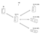
- FIGS. 2A to 2D schematically show the configuration of the reproducing apparatus 10, particularly the arrangement of the light emitting elements.
- 2A to 2D respectively show the function levels of the light emitting elements included in the reproducing apparatus 10.
- 2A shows the master playback device 11
- FIGS. 2B to 2D show the slave playback device 12.
- FIG. The playback device 10 shown in FIGS. 2A to 2D corresponds to the playback device 10 shown in FIG.
- Each playback device 10 includes a housing 15 and a plurality of speaker units 14.
- Each speaker unit 14 realizes a multi-channel type speaker.
- the master playback device 11 includes, for example, a plurality of light emitting elements L1 to L4, F1, F2, S1, and S2.
- each slave playback device 12 includes a plurality of light emitting elements.
- the slave playback device 12A shown in FIG. 2B is the same model as the master playback device 11.
- the model of the master playback device 11 and the slave playback device 12A is assumed to be the first model for convenience of explanation.
- the model (second model) of the slave playback device 12B shown in FIG. 2C and the model (third model) of the slave playback device 12C shown in FIG. 2D are different from the first model. That is, at least one of the plurality of slave playback apparatuses 12A to 12C is a different model slave playback apparatus different from the model of the master playback apparatus 11.
- the number of light emitting elements of the second model is less than that of the first model, and the function level of the light emitting elements of the second model is different from that of the first model.
- the arrangement of some of the light emitting elements also differs between these models.
- the number of light emitting elements of the third model is less than that of the second model (and the first model), and the function level of the light emitting elements of the third model is different from that of the second model (and the first model).
- at least one of the light emitting elements of the third model has a function level corresponding to at least one of the light emitting elements of the second model (and the first model). Is different. Details of this will be described later.
- the arrangement of some of the light emitting elements also differs between these models.
- One light emitting element is composed of, for example, one or more LEDs (Light Emitting Diode). Specifically, a dot-like, line-like, or planar light-emitting region is formed by one or more LEDs. The one light emitting area corresponds to one light emitting element.
- a light guide may be provided as an incidental configuration of the light emitting element.
- each light emitting element is schematically depicted as a star shape.
- these light emitting elements may be comprised by organic EL (Electro-Luminescence).
- Each light emitting element is arranged at a predetermined position of the housing 15 of the reproducing apparatus 10.
- four light emitting elements L1, L2, L3, and L4 are arranged at four corners of the housing 15, respectively.
- Two light emitting elements F1 and F2 are arranged adjacent to the speaker unit 14, respectively.
- Two light emitting elements S1 and S2 are arranged in the speaker unit 14, respectively.
- two light emitting elements L1 ′ and L3 ′ are arranged at the centers of both ends of the housing 15, respectively.
- Two light emitting elements F1 and F2 are arranged adjacent to the speaker unit 14, respectively.
- Two light emitting elements S1 ′ and S2 ′ are arranged in the speaker unit 14, respectively.
- two light emitting elements L1 ′′ and L3 ′′ are arranged at the centers of both ends of the housing 15, respectively.
- Two light emitting elements F1 and F2 are arranged adjacent to the speaker unit 14, respectively.
- L means a line-shaped light emitting region
- F means, for example, a flash that forms a point-like light emitting region
- S means an arrangement in the speaker unit 14.
- shape and arrangement of the light emitting areas are not limited to the forms shown in FIGS. 2A to 2D.
- the light emitting elements L1 to L4, L1 ′, and L3 ′ are configured to emit light in full color (for example, RGB values).
- the light emitting elements L1 ′′, L3 ′′, F1, F2, S1 ′, and S2 ′ are configured to emit light in, for example, a single color (for example, a white single color, but may be other colors).
- the light emitting elements S1 and S2 are configured to emit light in full color (for example, RGB values).
- the functional level of the light emitting elements S1 ′ and S2 ′ of the second model is inferior to that of the light emitting elements S1 and S2.
- the functional level of the light emitting elements L1 ′′ and L3 ′′ of the third model is inferior to that of the light emitting elements L1, L2, L3, L4, L1 ′, and L3 ′.
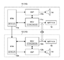
- FIG. 3 is a block diagram showing the system configuration of the playback apparatus 10.
- the master playback device 11 includes a BTM (Bluetooth module) 11a, a DSP (digital signal processor) 11b, an MCU (micro controller unit) 11c, and a light emitting device 16.
- the slave playback device 12 also basically has the same configuration as that of the master playback device 11.
- the master playback device 11 and the slave playback device 12 have memories such as RAM (Random Access Memory) and ROM (Read Only Memory) (not shown).
- the ROM stores programs and data necessary for realizing the operations and functions of the MCUs 11c and 12c.
- the light emitting device 16 includes a plurality of light emitting elements L1, L2, F1, S1, and the like, a driver for driving the same, and the like.
- the BTM 11a communicates with a BTM (not shown) of the computer 50 (see FIG. 1) and a BTM 12a with another playback device 10 based on the Bluetooth standard.
- the BTM 11a mainly performs communication of audio data and data related to light emission control.
- the BTMs 11a and 112a function as “transmitting units” and / or “receiving units”.
- the DSP 11b of the master playback device 11 mainly has a function of analyzing the audio data sent from the BTM 11a to generate analysis data, and outputting the generated analysis data to the MCU 11c.
- the DSP 11b performs frequency analysis as analysis processing, particularly processing for extracting low frequencies.
- the DSP 11b has a function of outputting audio data to the speaker unit 14 via, for example, a DA converter (not shown).
- the MCU 11c of the master playback device 11 acquires analysis data from the DSP 11b, and generates illumination information based on the analysis data.
- the MCU 11c mainly functions as a “generation unit”. Specifically, the MCU 11c detects the beat based on the bass component data as the analysis data.
- the DSP 11b and the MCU 11c may detect not only the beat but also the tempo, rhythm, and key (key).
- the MCU 11c can generate illumination information according to the audio data by generating the illumination information based on the information such as beats.
- Illumination information is information for associating light emission modes with the light emitting elements L1 to L4, F1, F2, S1, and S2 of the master playback device 11, respectively.
- the MCU 11c has a function of causing the plurality of light emitting elements to emit light in a light emitting mode based on the generated illumination information.
- the MCU 11c mainly functions as a “light emission control unit”.
- the MCU 11c outputs the generated illumination information to the BTM 11a.
- UART Universal Asynchronous Receiver Transmitter
- the MCU 11c includes a light emission control command generation unit (not shown) that generates a light emission control command for controlling light emission in synchronization with the slave playback device 12.
- the MCU 11c transmits the generated light emission control command to the slave playback device 12 via the BTM 11a. Thereby, synchronized light emission by each light emitting element is realized between the master playback device 11 and one or more slave playback devices 12.
- the MCU 11c further generates a playback control command for playing back the audio data in synchronization with the slave playback device 12.
- the MCU 11c transmits the generated playback control command to the slave playback device 12 via the BTM 11a.
- synchronized playback of audio data is realized between the master playback device 11 and one or more slave playback devices 12.
- the MCU 11c can realize synchronous reproduction by a known method using means such as a system clock, a counter, and frequency control.
- the MCU 11c can transmit the data including the illumination information, the light emission control command, and the reproduction control command to the slave reproduction apparatus 12 in the packet format using the data including the header portion and the audio data as the data portion.
- the MCU 11c may transmit the illumination information and / or the light emission control command to the slave playback device 12 independently of the audio data.
- the MCU 11c transmits data for synchronizing with audio data included in the illumination information and / or the light emission control command.
- the BTM 12a of the slave playback device 12 receives the illumination information, light emission control command, playback control command, and audio data from the master playback device 11.
- the MCU 12 c (or DSP 12 b) outputs audio data to the speaker unit 14 in synchronization with the master playback device 11. Further, the MCU 12c controls the light emission of its own light emitting element based on the illumination information and the light emission control command.
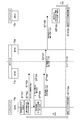
- FIG. 4 is a diagram showing a sequence of light emission synchronization control by the master playback device 11 and the slave playback device 12.
- the MCU 11c of the master playback device 11 generates a light emission control command (step 101). Thereby, for example, a timer that starts execution of light emission control after XX msec is set by the system clock of the MCU 11c (step 102).
- the MCU 11c requests the current time of the clock (BT clock) of the BTM 11a (step 103).
- the BTM clock transmits the current time of the BT clock to the MCU 11c in response to the request (step 104). For example, the current time of the BT clock is “1000”.
- the MCU 11c converts the execution time (start time) of the light emission control set in step 102 into a BT clock (step 105). For example, the converted BT clock is “1100”.
- the MCU 11c sends the generated light emission control command (execution time 1100) to the BTM 11a (step 106), and the BTM 11a sends the light emission control command (execution time 1100) to the BTM 12a of the slave playback device 12 (step 107).
- the BTM 12a of the slave playback device 12 sends the light emission control command to the MCU 12c (step 108). Then, the MCU 12c converts the execution time of the light emission control into the system clock, and sets the execution time of the light emission control after YYmsec (step 109).
- the master playback device 11 and the slave playback device 12 are connected by short-range wireless communication, the system clocks of the MCUs 11c and 12c are in a synchronized state. Therefore, after step 109, the master playback device 11 and the slave playback device 12 can simultaneously perform the light emission control at time 1100 (steps 110a and 110b).
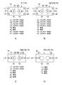
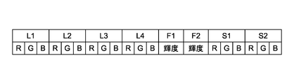
- FIG. 5 is a table showing the illumination information generated by the master playback device 11 according to the first embodiment.
- the illumination information is information indicating a light emission mode associated with each light emitting element.
- color values are set in the light emitting elements (first light emitting elements) L1 to L4, S1, and S2 that can emit light in full color.
- Luminance values are set for the light emitting elements (second light emitting elements) F1 and F2 that can emit light in a single color.
- the color value and the luminance value are set by a predetermined algorithm based on the beat detected by the beat detection based on the analysis data or the tempo, rhythm, and key detected based on the analysis data.
- the master playback device 11 transmits this illumination information to the slave playback device 12.
- the transmission interval is a predetermined time unit.
- the time unit is, for example, 30 msec to 200 msec.
- the slave playback device 12 receives the illumination information. Then, the MCU 12c of the slave playback device 12 assigns the illumination information corresponding to each light emitting element held by itself, and causes the light emitting elements to emit light. Each time the slave playback device 12 receives illumination information, that is, every time unit, the slave playback device 12 causes the light emitting element to emit light based on the illumination information. Specifically, the slave playback devices 12B and 12C of the second model and the third model execute the light emission control as follows.
- the number, arrangement, and function levels of the light emitting elements of the first model slave playback device 12A are all the same as those of the master playback device 11. Accordingly, the first model slave playback device 12A assigns the illumination information as it is to the light emitting element, and controls the light emission in the same light emission manner as the master playback device 11. The same applies to the second embodiment described later.
- the number, arrangement, and function levels of the light emitting elements of the second type slave playback device 12B are different from those of the master playback device 11.
- the light emitting elements L1 and L3 of the master reproduction device 11 and the light emitting elements L1 ′ and L3 ′ are arranged differently, but the light emitting elements L1 and L3 are assigned to the light emitting elements L1 ′ and L3 ′, respectively.
- This allocation method is a predetermined matter, that is, it is predetermined that the light emitting element L1 ′ corresponds to L1 and the light emitting element L3 ′ corresponds to L3.
- the MCU 12c of the slave playback device 12B generates illumination information by associating the light emission mode data (color values) of the light emitting elements L1 and L3 with L1 ′ and L3 ′.
- the light emitting elements S1 and S2 of the master playback device 11 are assigned to the light emitting elements S1 ′ and S2 ′, respectively.
- the arrangement of the light emitting elements S1, S2 and S1 ′, S2 ′ is the same among these models, but the functional levels of S1 ′, S2 ′ are monochromatic, and are different from the functional levels of S1, S2.
- the MCU 12c of the slave playback device 12B converts the color values of S1 and S2 of the received illumination information into luminance values by a predetermined algorithm, and uses the luminance values as the light emission modes of the light emitting elements S1 ′ and S2 ′. Illumination information is generated so as to be associated.
- the illumination information is generated so that the light emission modes of the light emitting elements F1 and F2 of the master reproducing device 11 are directly associated with the light emitting elements F1 and F2 of the second model slave reproducing device 12B. Since the slave playback device 12B does not have the light emitting elements corresponding to the light emitting elements L2 and L4 of the master playback device 11, the light emitting modes of these light emitting elements L2 and L4 are excluded or ignored.
- the MCU 12c of the slave playback device 12B updates the illumination information as described above based on the illumination information received from the master playback device 11, and executes the light emission control of the light emitting element based on this.
- the MCU 12c functions as a “light emission control unit”.
- the number, arrangement, and function levels of the light emitting elements of the third model slave playback device 12C are different from those of the master playback device 11.
- the light emitting elements L1 and L3 and the light emitting elements L1 "and L3" of the master playback device 11 are arranged differently, but the light emitting elements L1 and L3 are assigned to the light emitting elements L1 "and L3", respectively.
- This allocation method is a predetermined matter, that is, it is determined that the light emitting element L1 "corresponds to L1 and the light emitting element L3" corresponds to L3.
- the MCU 12c of the slave playback device 12 generates illumination information by associating the light emission mode data (color values) of the light emitting elements L1 and L3 with L1 ′′ and L3 ′′ as luminance values according to the above formula 1. .
- the illumination information is generated such that the light emission modes of the light emitting elements F1 and F2 of the master playback device 11 are directly associated with the light emitting elements F1 and F2 of the third model slave playback device 12. Since the slave playback device 12 does not have the light emitting elements corresponding to the light emitting elements L2 and L4 of the master playback device 11, the light emitting modes of these light emitting elements L2 and L4 are excluded or ignored.
- the MCU 12c of the slave playback device 12C updates the illumination information based on the illumination information received from the master playback device 11, and executes the light emission control of the light emitting element based on this.
- the master reproducing device 11 can individually control light emission for each light emitting element based on the illumination information.
- the slave playback device 12 can receive the illumination information, and can realize light emission according to the audio data in synchronization with the master playback device 11 based on the illumination information or the updated illumination information.
- the interest of the user can be improved.
- Multiple users can enjoy music and light, both indoors and outdoors.
- FIG. 6 is a table showing illumination information generated by the master playback device 11 according to the second embodiment.
- This illumination information defines a pattern number (Pt.No) and a color (Color) that define light emission patterns associated with the individual light emission elements L1 to L4, F1, F2, S1, and S2.
- Color table Col-Tbl.No).
- the light emission pattern is a pattern of light that is predefined for each pattern number. There are several tens to several hundreds of light emission patterns, for example.
- the light emission pattern defines how the color is changed using the color table in the illumination information based on the analysis data (based on information such as beats).
- the color table is a table indicating a range of color change defined in advance for each color table number. That is, one color table indicates data for changing the color within a range defined by a combination of a plurality of color values (RGB values).
- One color table defines the color range of the light emission pattern of each light emitting element in the illumination information. For example, one color table defines one or more basic colors and a gradation color or similar color centered on them. There are, for example, several to several tens of color tables.
- the transmission interval of this illumination information by the master playback device 11 is a predetermined time unit.
- the time unit is a time for each timing at which at least one of the light emission modes corresponding to each light emitting element and color of the illumination information changes.
- the timing at which at least one of the light emission mode data changes is, for example, the timing at which the beat, tempo, rhythm, key, or the like changes, or the timing at which the pattern length determined by the number of measures changes.
- the second model slave playback device 12B receives the illumination information from the master playback device 11. Then, the MCU 12c generates illumination information and controls light emission by assigning the light emission modes of the light emitting elements L1 and L3 of the master playback device 11 as the light emission modes of its own light emitting elements L1 ′ and L3 ′.
- the light emission modes of the light emitting elements F1 and F2 of the master reproducing device 11 are realized as they are by the light emitting elements F1 and F2 of the slave reproducing device 12.
- the MCU 12c of the second model slave playback device 12B assigns the light emission modes of the light emitting elements S1 and S2 of the master playback device 11 as the light emission modes of its own light emitting elements S1 ′ and S2 ′, and provides the illumination information. Generate and control light emission.
- the MCU 12c converts the plurality of color values in the color table into luminance values using the above Equation 1, and realizes the light emission mode of the light emitting elements S1 ′ and S2 ′.
- the slave playback device 12C of the third model receives the illumination information from the master playback device 11. Then, the MCU 12c generates illumination information so as to assign the light emission modes of the light emitting elements L1 and L3 of the master playback device 11 as the light emission modes of its own light emitting elements L1 "and L3", and controls the light emission. In this case, the MCU 12c converts the plurality of color values in the color table into luminance values using the above Equation 1, and realizes the light emission mode of the light emitting elements L1 "and L3".
- the light emission modes of the light emitting elements F1 and F2 of the master reproducing device 11 are realized as they are by the light emitting elements F1 and F2 of the slave reproducing device 12C.
- the same effect as in the first embodiment can be obtained.
- the illumination information includes a light emission pattern and a color table, a wider variety of illuminations can be realized as compared to the first embodiment.
- the playback system 100 includes three types of slave playback devices 12A to 12C. However, the playback system 100 only needs to include at least one type of one or more slave playback devices 12.
- At least one of the slave playback devices 12 may include only one light emitting element.
- the MCU 12c of each slave playback device 12 can control light emission using the same illumination information in the flow of the light emitting element of the slave playback device 12A, the light emitting element of the slave playback device 12B, and the light emitting element of the slave playback device 12C. It is. That is, the light emission changes so that the delay effect is exhibited in each slave playback device 12. In this case, it is desirable to use the illumination information according to the second embodiment.
- the master playback device may determine the configuration and specifications of the slave playback device. For example, at the time of the connection, the master playback device may compare the number of light emitting elements of its own light emitting element with the light emitting elements of the slave playback device, the arrangement, and the function level, and send the comparison information to the slave playback device. .
- these playback devices do not need to store in advance information on the number and arrangement of light emitting elements of the connected playback device, and can acquire the information at the time of connection.
- the design of the arrangement, number, and function level of the light emitting elements of each playback device 10 can be changed as appropriate.
- the function level of the light emitting element of the master playback device 11 is higher than that of the slave playback devices 12B and 12C of the second and third models.
- the master playback device 11 may have a configuration inferior to that of the second model and the third model.
- a master playback device capable of performing synchronized playback of audio data with one or more slave playback devices, A plurality of light emitting elements; Based on analysis data obtained by analyzing audio data, a generation unit configured to generate illumination information that associates a light emission mode with a light emitting element of the plurality of light emitting elements; A transmitter configured to transmit the generated illumination information to the one or more slave playback devices; And a light emission control unit configured to cause the plurality of light emitting elements to emit light in the light emission mode based on the illumination information.
- the slave playback device has at least one light emitting element, A light emission control command generating unit configured to generate a light emission control command for synchronizing light emission by the plurality of light emitting elements and light emission by the light emitting elements of the slave playback device; The transmission unit is configured to transmit the generated light emission control command to the slave playback device. Master playback device.
- At least one of the one or more slave playback devices is a different model having at least one light emitting element configured such that at least one of the number, arrangement, and function level of the plurality of light emitting elements of the master playback device is different.
- a slave playback device The transmitting unit is configured to transmit the illumination information to the heterogeneous slave playback device. Master playback device. (4) The master playback device according to any one of (1) to (3), The generation unit generates illumination information in which a color value is associated with a first light emitting element and a luminance value is associated with a second light emitting element among the plurality of light emitting elements as the light emission mode of the illumination information. Master playback device that is composed of. (5) The master playback device according to any one of (1) to (3), The generation unit is configured to generate illumination information including a light emission pattern associated with each of the plurality of light emitting elements and a color table defining a combination of a plurality of color values as the light emission mode of the illumination information. Master playback device.
- the master playback device is configured to generate illumination information in which a color range of a light emission pattern according to the light emission pattern is defined by a combination of the plurality of color values defined by the color tail.
- a slave playback device capable of performing synchronous playback of audio data with a master playback device, One or more light emitting elements; Illumination information generated by the master playback device having audio data and a plurality of light emitting elements, wherein the illumination information associates light emission modes with the light emitting elements of the plurality of light emitting elements generated based on the analysis data of the audio data
- a receiver configured to receive information from the master playback device; And a light emission control unit configured to cause the one or more light emitting elements to emit light based on the received illumination information.
- the slave playback device is configured to receive a light emission control command transmitted from the master reproduction device for synchronizing light emission by the plurality of light emitting elements and light emission by the light emitting elements of the slave reproduction device. Slave playback device.
- the slave playback device according to (7) or (8), A slave playback device in which at least one of the number and arrangement of the one or more light emitting elements is different from that of the plurality of light emitting elements of the master playback device.
- the slave playback device according to any one of (7) to (9), At least one function level among the one or more light emitting elements is different from a function level of at least one light emitting element corresponding in advance among the plurality of light emitting elements of the master reproducing apparatus.
- the slave playback device according to (10), The master reproduction device is configured to generate illumination information associating information including a color value with at least one of the plurality of light emitting elements as the light emission mode of the illumination information,
- the light emission control unit is configured to convert the color value with a predetermined algorithm so that at least one of the one or more light emitting elements emits light.
- the slave playback device according to (11), The light emission control unit is configured to convert the color value into a luminance value.
- a light emission method by a slave playback device capable of performing synchronous playback of audio data with a master playback device, Illumination information generated by the master playback device having audio data and a plurality of light emitting elements, wherein the illumination information associates light emission modes with the light emitting elements of the plurality of light emitting elements generated based on the analysis data of the audio data Information from the master playback device, A light emitting method for causing one or more light emitting elements of the slave playback device to emit light based on the received illumination information.
- the function level of at least one of the one or more light emitting elements is different from the function level of the plurality of light emitting elements of the master playback device,
- the master reproduction device is configured to generate illumination information associating information including a color value with at least one of the plurality of light emitting elements as the light emission mode of the illumination information, In the light emission of the one or more light emitting elements, the color value is converted by a predetermined algorithm to emit at least one of the one or more light emitting elements.
Abstract
【解決手段】マスター再生装置は、1以上のスレーブ再生装置とオーディオデータの同期再生を実行可能なマスター再生装置である。前記マスター再生装置は、複数の発光要素と、生成部と、送信部と、発光制御部とを具備する。前記生成部は、オーディオデータを解析して得られる解析データに基づき、前記複数の発光要素の発光要素に発光態様を関連付けるイルミネーション情報を生成するように構成される。前記送信部は、前記生成されたイルミネーション情報を前記1以上のスレーブ再生装置に送信するように構成される。前記発光制御部は、前記イルミネーション情報に基づく前記発光態様で前記複数の発光要素を発光させるように構成される。
Description
本技術は、オーディオデータを複数の再生装置で同期して再生し、またこれらの装置が備える発光要素を発光させるための技術に関する。
従来、家庭内にホームネットワークを構築し、そこに接続された再生装置により、音楽や映像等のコンテンツを再生するシステムが知られている。例えば特許文献1には、ネットワークに接続された複数の再生装置によりグループを構成し、同一のコンテンツを同期再生させるマルチルーム再生の制御方法について記載されている(明細書段落[0043]~[0046]、図8参照)。
特許文献2には、照明装置を備えた音響再生装置が記載されている。この音響再生装置では、再生されるオーディオデータが解析される。その解析結果に応じて、照明装置の発光タイミングや明るさ等が適宜制御される。これによりオーディオコンテンツの再生を、聴覚のみならず視覚からも楽しむことが可能となり、高い興奮や高揚感を体験することが可能となる(明細書段落[0026]~[0041]参照)。
今後も、複数の再生装置によるオーディオデータの再生技術は普及していくものと考えられる。したがって、ユーザーがより楽しむことができる製品やサービスを提供することが求められる。
本開示の目的は、ユーザーの興趣の向上を図るためのマスター再生装置、スレーブ再生装置およびこれらの再生方法を提供することにある。
上記目的を達成するため、一形態に係るマスター再生装置は、1以上のスレーブ再生装置とオーディオデータの同期再生を実行可能なマスター再生装置である。
前記マスター再生装置は、複数の発光要素と、生成部と、送信部と、発光制御部とを具備する。
前記生成部は、オーディオデータを解析して得られる解析データに基づき、前記複数の発光要素の発光要素に発光態様を関連付けるイルミネーション情報を生成するように構成される。
前記送信部は、前記生成されたイルミネーション情報を前記1以上のスレーブ再生装置に送信するように構成される。
前記発光制御部は、前記イルミネーション情報に基づく前記発光態様で前記複数の発光要素を発光させるように構成される。
前記マスター再生装置は、複数の発光要素と、生成部と、送信部と、発光制御部とを具備する。
前記生成部は、オーディオデータを解析して得られる解析データに基づき、前記複数の発光要素の発光要素に発光態様を関連付けるイルミネーション情報を生成するように構成される。
前記送信部は、前記生成されたイルミネーション情報を前記1以上のスレーブ再生装置に送信するように構成される。
前記発光制御部は、前記イルミネーション情報に基づく前記発光態様で前記複数の発光要素を発光させるように構成される。
複数の発光要素を有するマスター再生装置は、イルミネーション情報に基づいてそれら発光要素ごとに個別に発光を制御し、また、そのイルミネーション情報を1以上のスレーブ再生装置に送信する。これにより、マスター再生装置は、スレーブ再生装置と同期してオーディオデータを再生し、そのオーディオデータに応じた発光を行うことができる。これにより、ユーザーの興趣の向上が図られる。
前記スレーブ再生装置は、少なくとも1つの発光要素を有してもよい。前記マスター再生装置は、前記複数の発光要素による発光と、前記スレーブ再生装置の前記発光要素による発光とを同期させるための発光制御コマンドを生成するように構成された発光制御コマンド生成部をさらに具備してもよい。前記送信部は、前記生成された発光制御コマンドを前記スレーブ再生装置に送信するように構成されていてもよい。
これにより、マスター再生装置は、スレーブ再生装置と同期して発光要素を発光させることができる。
前記1以上スレーブ再生装置のうち少なくとも1つは、前記マスター再生装置の前記複数の発光要素の数、配置および機能レベルのうち少なくとも1つが異なるように構成された1以上の発光要素を有する異機種スレーブ再生装置であってもよい。前記送信部は、前記イルミネーション情報を前記異機種スレーブ再生装置に送信するように構成されていてもよい。
このマスター再生装置は、自身が使用するイルミネーション情報と同じイルミネーション情報を、異機種スレーブ再生装置に送信する。異機種スレーブ再生装置は、発光要素の数または機能レベルが異なる発光要素を有していたとしても、そのイルミネーション情報を使用して発光制御を実行する。
前記生成部は、前記イルミネーション情報の前記発光態様として、前記複数の発光要素のうち、第1発光要素にはカラー値を関連付け、第2発光要素には輝度値を関連付けたイルミネーション情報を生成するように構成されていてもよい。
これにより、マスター再生装置は複数の発光要素を用いて多彩なイルミネーションを実現できる。
前記生成部は、前記イルミネーション情報の前記発光態様として、前記複数の発光要素にそれぞれ関連付けられた発光パターンと、複数のカラー値の組み合わせを規定するカラーテーブルとを含むイルミネーション情報を生成するように構成されていてもよい。
これにより、マスター再生装置は複数の発光要素を用いて、上述のカラー値や輝度値を関連付けたイルミネーション情報に比べ、より多彩なイルミネーションを実現できる。
これにより、マスター再生装置は複数の発光要素を用いて、上述のカラー値や輝度値を関連付けたイルミネーション情報に比べ、より多彩なイルミネーションを実現できる。
前記生成部は、前記発光パターンによる発光パターンのカラー範囲が、前記カラーテールで規定された前記複数のカラー値の組み合わせで規定されるイルミネーション情報を生成するように構成されていてもよい。
一形態に係るスレーブ再生装置は、マスター再生装置とオーディオデータの同期再生を実行可能なスレーブ再生装置である。
前記スレーブ再生装置は、1以上の発光要素と、受信部と、発光制御部とを具備する。
前記受信部は、オーディオデータと、複数の発光要素を有する前記マスター再生装置により生成されるイルミネーション情報であって、前記オーディオデータの解析データに基づき生成された、前記複数の発光要素の発光要素に発光態様を関連付けるイルミネーション情報とを、前記マスター再生装置から受信するように構成される。
前記発光制御部は、前記受信したイルミネーション情報に基づき、前記1以上の発光要素を発光させるように構成される。
前記スレーブ再生装置は、1以上の発光要素と、受信部と、発光制御部とを具備する。
前記受信部は、オーディオデータと、複数の発光要素を有する前記マスター再生装置により生成されるイルミネーション情報であって、前記オーディオデータの解析データに基づき生成された、前記複数の発光要素の発光要素に発光態様を関連付けるイルミネーション情報とを、前記マスター再生装置から受信するように構成される。
前記発光制御部は、前記受信したイルミネーション情報に基づき、前記1以上の発光要素を発光させるように構成される。
複数の発光要素を有するマスター再生装置は、イルミネーション情報に基づいてそれら発光要素ごとに個別に発光を制御し、スレーブ再生装置は、マスター再生装置で生成されたイルミネーション情報を受信する。これにより、スレーブ再生装置は、マスター再生装置と同期してオーディオデータを再生し、イルミネーション情報に基づきそのオーディオデータに応じて1以上の発光要素を発光させることができる。これにより、ユーザーの興趣の向上が図られる。
前記受信部は、前記複数の発光要素による発光と、前記スレーブ再生装置の前記発光要素による発光とを同期させるための、前記マスター再生装置から送信された発光制御コマンドを受信するように構成されていてもよい。
これにより、スレーブ再生装置は、マスター再生装置と同期して発光要素を発光させることができる。
前記1以上の発光要素の数および配置のうち少なくとも一方が、前記マスター再生装置の前記複数の発光要素のそれとは異なっていてもよい。
前記1以上の発光要素のうち少なくとも1つの機能レベルが、前記マスター再生装置の前記複数の発光要素のうち予め対応する少なくとも1つの発光要素の機能レベルとは異なっていてもよい。
前記マスター再生装置は、前記イルミネーション情報の前記発光態様として、前記複数の発光要素のうち少なくとも1つに、カラー値を含む情報を関連付けたイルミネーション情報を生成するように構成されていてもよい。前記発光制御部は、前記カラー値を所定のアルゴリズムで変換して、前記1以上の発光要素のうち少なくとも1つを発光させるように構成されていてもよい。
マスター再生装置が使用するイルミネーション情報と同じイルミネーション情報を、このスレーブ再生装置が受信する。このスレーブ再生装置の発光要素の1つの機能レベルが異なっていたとしても、発光制御部は、マスター再生装置のカラー値をそのまま使わず、これを変換することにより、マスター再生装置に応じた発光を行うことができる。
前記発光制御部は、前記カラー値を輝度値に変換するように構成されていてもよい。
一形態に係る発光方法は、1以上のスレーブ再生装置とオーディオデータの同期再生を実行可能なマスター再生装置による発光方法である。
オーディオデータが解析されて解析データが生成される。
前記取得された解析データに基づき、前記マスター再生装置が有する複数の発光要素の発光要素に発光態様を関連付けるイルミネーション情報が生成される。
前記生成されたイルミネーション情報が前記1以上のスレーブ再生装置に送信される。
前記イルミネーション情報に基づく前記発光態様で前記複数の発光要素が発光させられる。
オーディオデータが解析されて解析データが生成される。
前記取得された解析データに基づき、前記マスター再生装置が有する複数の発光要素の発光要素に発光態様を関連付けるイルミネーション情報が生成される。
前記生成されたイルミネーション情報が前記1以上のスレーブ再生装置に送信される。
前記イルミネーション情報に基づく前記発光態様で前記複数の発光要素が発光させられる。
一形態に係る発光方法は、マスター再生装置とオーディオデータの同期再生を実行可能なスレーブ再生装置による発光方法である。
オーディオデータと、複数の発光要素を有する前記マスター再生装置により生成されるイルミネーション情報であって、前記オーディオデータの解析データに基づき生成された、前記複数の発光要素の発光要素に発光態様を関連付けるイルミネーション情報とが、前記マスター再生装置から受信される。
前記受信したイルミネーション情報に基づき、前記スレーブ再生装置が有する1以上の発光要素が発光させられる。
オーディオデータと、複数の発光要素を有する前記マスター再生装置により生成されるイルミネーション情報であって、前記オーディオデータの解析データに基づき生成された、前記複数の発光要素の発光要素に発光態様を関連付けるイルミネーション情報とが、前記マスター再生装置から受信される。
前記受信したイルミネーション情報に基づき、前記スレーブ再生装置が有する1以上の発光要素が発光させられる。
前記1以上の発光要素のうち少なくとも1つの機能レベルが、前記マスター再生装置の前記複数の発光要素の機能レベルとは異なっていてもよい。前記マスター再生装置は、前記イルミネーション情報の前記発光態様として、前記複数の発光要素のうち少なくとも1つに、カラー値を含む情報を関連付けたイルミネーション情報を生成するように構成されていてもよい。前記1以上の発光要素の発光では、前記カラー値を所定のアルゴリズムで変換して、前記1以上の発光要素のうち少なくとも1つが発光させられる。
以上、本技術によれば、ユーザーの興趣の向上を図ることができる。
なお、ここに記載された効果は必ずしも限定されるものではなく、本開示中に記載されたいずれかの効果であってもよい。
以下、本技術に係る実施形態を、図面を参照しながら説明する。
1.システム構成
図1は、本技術の一実施形態に係る再生システムの構成を示す図である。この再生システム100は、例えばコンピュータ50と、オーディオデータを再生可能な複数の再生装置10とを備える。
コンピュータ50は、典型的には、スマートフォンやタブレット型コンピュータである。コンピュータ50は、ラップトップ型、あるいはデスクトップ型のものであってもよい。
複数の再生装置10は、主にスピーカーとして機能する。複数の再生装置10は、1つのマスター再生装置11と、このマスター再生装置11に接続可能な1以上のスレーブ再生装置12とを含む。本実施形態では、複数のスレーブ再生装置12がマスター再生装置11にマルチ接続可能となっている。
コンピュータ50とマスター再生装置11とは、近距離無線通信を利用して接続され得る。また、マスター再生装置11とスレーブ再生装置12も近距離無線通信を利用して接続され得る。近距離無線通信の規格として、本実施形態ではBluetooth(登録商標、以下同じ)が用いられる。近距離無線通信として、Bluetoothの代わりにZigbeeが用いられてもよい。
近距離無線通信に限られず、WiFi等の無線LANにより、これらの機器が接続されてもよい。マスター再生装置11は、複数のスレーブ再生装置12とマルチ接続できるように構成されている。
コンピュータ50は、オーディオデータを記憶する図示しないストレージを備えている。ユーザーによりコンピュータ50が操作されることで、コンピュータ50は、そのストレージ内のオーディオデータをマスター再生装置11に送信し、マスター再生装置11はこれを再生することができる。また、マスター再生装置11は、後述するようにそのオーディオデータをスレーブ再生装置12に送信し、スレーブ再生装置12は、マスター再生装置11と同期してそのオーディオデータを再生することができる。
2.再生装置
2.1)再生装置の外観上の構成
図2A~Dの上は、再生装置10の構成、特に発光要素の配置を模式的にそれぞれ示す。図2A~Dの下は、それら再生装置10が有する発光要素の機能レベルをそれぞれ示す。図2Aはマスター再生装置11、図2B~Dはスレーブ再生装置12を示す。図2A~Dに示す再生装置10は、図1に示す再生装置10にそれぞれ対応している。
各再生装置10は、ハウジング15と、複数のスピーカー部14とを備える。各スピーカー部14により、複数チャンネル型のスピーカーが実現される。
マスター再生装置11は、例えば複数の発光要素L1~L4、F1、F2、S1、S2を備える。各スレーブ再生装置12も同様に複数の発光要素を備える。
図2Bに示すスレーブ再生装置12Aは、マスター再生装置11と同一機種である。マスター再生装置11およびスレーブ再生装置12Aの機種を、説明の便宜上、第1機種とする。図2Cに示すスレーブ再生装置12Bの機種(第2機種)、図2Dに示すスレーブ再生装置12Cの機種(第3機種)は、第1機種とはそれぞれ異なる。すなわち、複数のスレーブ再生装置12A~12Cのうち少なくとも1つはマスター再生装置11の機種とは異なる異機種スレーブ再生装置である。
具体的には、第2機種の発光要素の数は第1機種のそれより少なく、第2機種の発光要素の機能レベルは第1機種のそれとは異なる。また、一部の発光要素の配置もそれらの機種間で異なる。
第3機種の発光要素の数は第2機種(および第1機種)のそれより少なく、第3機種の発光要素の機能レベルは第2機種(および第1機種)のそれとは異なる。具体的には、第3機種の1以上の発光要素のうち少なくとも1つの機能レベルが、第2機種(および第1機種)の複数の発光要素のうち予め対応する少なくとも1つの発光要素の機能レベルとは異なる。これについての詳細は後述する。また、一部の発光要素の配置もそれらの機種間で異なる。
1つの発光要素は、例えば1以上のLED(Light Emitting Diode)で構成されている。具体的には、1以上のLEDにより点状、ライン状、または面状の発光領域が形成される。その1つの発光領域が1つの発光要素に対応する。また、発光要素の付随的な構成として、ライトガイドも設けられる場合もある。図2では、本技術を理解しやすくするため、各発光要素を模式的にスター型として描かれている。なお、これら発光要素は有機EL(Electro-Luminescence)により構成されていてもよい。
各発光要素は、再生装置10のハウジング15の所定の位置にそれぞれ配置される。例えば図2A、Bに示す第1機種では、ハウジング15の4角に、4つの発光要素L1、L2、L3、L4がそれぞれ配置されている。スピーカー部14に隣接して2つの発光要素F1、F2がそれぞれ配置されている。そして、スピーカー部14内に2つの発光要素S1、S2がそれぞれ配置されている。
図2Cに示す第2機種のスレーブ再生装置12Bでは、ハウジング15の両端中央に2つの発光要素L1'、L3'がそれぞれ配置されている。スピーカー部14に隣接して2つの発光要素F1、F2がそれぞれ配置されている。そして、スピーカー部14内に2つの発光要素S1'、S2'がそれぞれ配置されている。
図2Dに示す第3機種のスレーブ再生装置12Cでは、ハウジング15の両端中央に2つの発光要素L1"、L3"がそれぞれ配置されている。そして、スピーカー部14に隣接して2つの発光要素F1、F2がそれぞれ配置されている。
なお、「L」はライン状の発光領域を、「F」は例えば点状の発光領域を形成するフラッシュを、「S」はスピーカー部14内の配置を意味する。しかし、発光領域の形状や配置は、図2A~Dに示す形態に限られない。
発光要素L1~L4、L1'、L3'は、フルカラー(例えばRGB値)で発光するように構成される。発光要素L1"、L3"、F1、F2、S1'、S2'は、例えば単色(例えば白色系の単色であるが、他の色でもよい)で発光するように構成される。発光要素S1、S2は、フルカラー(例えばRGB値)で発光するように構成される。
すなわち、第2機種の発光要素S1'、S2'の機能レベルは、発光要素S1、S2より劣る。また、第3機種の発光要素L1"、L3"の機能レベルは、発光要素L1、L2、L3、L4、L1'、L3'より劣る。
2.2)再生装置のシステム構成
図3は、再生装置10のシステム構成を示すブロック図である。マスター再生装置11は、BTM(Bluetooth Module)11a、DSP(Digital Signal Processor)11b、MCU(Micro Controller Unit)11c、および、発光デバイス16を備える。スレーブ再生装置12も、基本的にはマスター再生装置11の構成と同様の構成を有する。
マスター再生装置11およびスレーブ再生装置12は、これらの構成要素の他、図示しないがRAM(Random Access Memory)、ROM(Read Only Memory)等のメモリを有する。ROMには、MCU11c、12cの動作や機能を実現するために必要なプログラムやデータが記憶される。
発光デバイス16は、複数の発光要素L1、L2、F1、S1等や、それを駆動するドライバ等を含む。
BTM11aは、Bluetooth規格に基づいて、コンピュータ50(図1参照)の図示しないBTMや、他の再生装置10とのBTM12aとの間で通信を行う。BTM11aは、主に、オーディオデータおよび発光制御に関するデータの通信を行う。BTM11a、112aは、「送信部」および/または「受信部」として機能する。
マスター再生装置11のDSP11bは、主に、BTM11aから送られたオーディオデータの解析して解析データを生成し、生成された解析データをMCU11cに出力する機能を有する。DSP11bは、本実施形態では、解析処理として周波数解析、特に低周波を抽出する処理を行う。また、DSP11bは、例えば図示しないDA変換器を介して、オーディオデータをスピーカー部14に出力する機能を有する。
マスター再生装置11のMCU11cは、DSP11bから解析データを取得し、解析データに基づきイルミネーション情報を生成する。この場合、主にMCU11cは「生成部」として機能する。具体的には、MCU11cは解析データとしての低音成分のデータに基づき、ビートを検出する。DSP11bおよびMCU11cは、ビートだけでなく、テンポ、リズム、調(キー)を検出するようにしてもよい。
そして、MCU11cは、それらのビート等の情報に基づきイルミネーション情報を生成することにより、オーディオデータに応じたイルミネーション情報を生成することができる。
イルミネーション情報は、マスター再生装置11の発光要素L1~L4、F1、F2、S1、S2に発光態様をそれぞれ関連付ける情報である。MCU11cは、生成したイルミネーション情報に基づく発光態様で前記複数の発光要素を発光させる機能を有する。この場合、主にMCU11cは「発光制御部」として機能する。
MCU11cは、生成したイルミネーション情報をBTM11aに出力する。MCU11cからBTM11aへの送信には、例えばUART(Universal Asynchronous Receiver Transmitter)が用いられる。
また、MCU11cは、スレーブ再生装置12と同期して発光を制御するための発光制御コマンドを生成する発光制御コマンド生成部(図示せず)を含む。MCU11cは、生成した発光制御コマンドを、BTM11aを介してスレーブ再生装置12に送信する。これにより、マスター再生装置11と1以上のスレーブ再生装置12との間で、各発光要素による同期発光が実現される。
MCU11cは、スレーブ再生装置12とオーディオデータを同期して再生するための再生制御コマンドをさらに生成する。MCU11cは、生成した再生制御コマンドを、BTM11aを介してスレーブ再生装置12に送信する。これにより、マスター再生装置11と1以上のスレーブ再生装置12との間で、オーディオデータの同期再生が実現される。MCU11cは、システムクロック、カウンタ、周波数制御等の手段を利用して公知の方法により同期再生を実現できる。
MCU11cは、上記イルミネーション情報、発光制御コマンド、および再生制御コマンドを含むデータをヘッダ部とし、オーディオデータをデータ部として、これらのデータをパケット形式でスレーブ再生装置12に送信することができる。
あるいは、MCU11cは、イルミネーション情報および/または発光制御コマンドを、オーディオデータとは独立してスレーブ再生装置12に送信するようにしてもよい。この場合、MCU11cは、オーディオデータに同期させるためのデータを、イルミネーション情報および/または発光制御コマンドに含ませて送信する。
スレーブ再生装置12のBTM12aは、マスター再生装置11からの上記イルミネーション情報、発光制御コマンド、再生制御コマンド、オーディオデータを受信する。MCU12c(あるいはDSP12b)は、マスター再生装置11に同期してオーディオデータをスピーカー部14に出力する。また、MCU12cは、イルミネーション情報および発光制御コマンド基づき、自身の発光要素の発光を制御する。
3.発光同期制御
図4は、マスター再生装置11およびスレーブ再生装置12による発光の同期制御のシーケンスを示す図である。
マスター再生装置11のMCU11cは、発光制御コマンドを生成する(ステップ101)。これにより、例えばXXmsec後に発光制御の実行が開始されるようなタイマーが、MCU11cのシステムクロックで設定される(ステップ102)。MCU11cは、BTM11aのクロック(BTクロック)の現時刻を要求する(ステップ103)。BTMクロックはその要求に応じてBTクロックの現時刻をMCU11cに送信する(ステップ104)。BTクロックの現時刻を例えば"1000"とする。
MCU11cは、ステップ102で設定された発光制御の実行時刻(開始時刻)を、BTクロックに換算する(ステップ105)。例えば換算後のBTクロックを"1100"とする。MCU11cは、生成した発光制御コマンド(実行時刻1100)をBTM11aに送り(ステップ106)、BTM11aはその発光制御コマンド(実行時刻1100)をスレーブ再生装置12のBTM12aに送る(ステップ107)。
スレーブ再生装置12のBTM12aは、その発光制御コマンドをMCU12cに送る(ステップ108)。そうすると、MCU12cは、発光制御の実行時刻をシステムクロックに換算し、YYmsec後に発光制御の実行時刻を設定する(ステップ109)。
本シーケンスの前提として、マスター再生装置11およびスレーブ再生装置12が近距離無線通信で接続された時点で、互いのMCU11c、12cのシステムクロックは同期状態にある。したがって、ステップ109後、マスター再生装置11およびスレーブ再生装置12は、発光制御を時刻1100に同時に実行することができる(ステップ110a、110b)。
4.発光制御についての実施形態
4.1)実施形態1
図5は、マスター再生装置11により生成された、実施形態1に係るイルミネーション情報を示すテーブルである。イルミネーション情報は、上記したように、発光要素ごとにこれらに関連付けられた発光態様を示す情報である。
このイルミネーション情報の例では、フルカラーで発光可能な発光要素(第1発光要素)L1~L4、S1、S2には、カラー値(RGB値)が設定される。単色で発光可能な発光要素(第2発光要素)F1、F2には輝度値が設定される。カラー値および輝度値は、解析データに基づくビート検出により検出されたビート、あるいは、解析データに基づき検出されたテンポ、リズム、調に基づき、所定のアルゴリズムで設定される。
マスター再生装置11は、このイルミネーション情報をスレーブ再生装置12に送信する。その送信間隔は、所定の時間単位である。その時間単位は、例えば30msec~200msecである。
スレーブ再生装置12がイルミネーション情報を受信する。そうすると、スレーブ再生装置12のMCU12cは、イルミネーション情報を、自身が持つ各発光要素に対応する割り当て、それら発光要素を発光させる。スレーブ再生装置12は、イルミネーション情報を受信するごと、つまり上記時間単位ごとに、そのイルミネーション情報に基づき発光要素を発光させる。具体的には、第2機種、第3機種のスレーブ再生装置12B、12Cは、以下のようにして発光制御を実行する。
4.1.1)第1機種のスレーブ再生装置12Aの発光制御
第1機種のスレーブ再生装置12A(図2A参照)の発光要素の数、配置および機能レベルは、マスター再生装置11のそれとすべて同じである。したがって、第1機種のスレーブ再生装置12Aは、イルミネーション情報をそのまま自身の発光要素に割り当て、マスター再生装置11と同じ発光態様で発光を制御する。これは、後述する実施形態2でも同様である。
4.1.2)第2機種のスレーブ再生装置12Bの発光制御
一方、第2機種のスレーブ再生装置12B(図2C参照)の発光要素の数、配置および機能レベルは、マスター再生装置11のそれと異なる。例えば、マスター再生装置11の発光要素L1、L3と、発光要素L1'、L3'とは異なる配置であるが、発光要素L1、L3が、発光要素L1'、L3'にそれぞれ割り当てられる。この割り当て方は予め決められた事項であり、すなわち、発光要素L1'がL1に対応し、発光要素L3'がL3に対応することが予め決められている。そして、スレーブ再生装置12BのMCU12cは、発光要素L1、L3の発光態様のデータ(カラー値)を、L1'、L3'に関連付けるようにして、イルミネーション情報を生成する。
また、第2機種のスレーブ再生装置12Bでは、マスター再生装置11の発光要素S1、S2が、発光要素S1'、S2'にそれぞれ割り当てられる。それらの機種間で発光要素S1、S2と、S1'、S2'との配置は同じであるが、S1'、S2'の機能レベルは単色であり、S1、S2の機能レベルとは異なる。この場合、スレーブ再生装置12BのMCU12cは、受信したイルミネーション情報のS1、S2のカラー値を輝度値に所定のアルゴリズムで変換し、その輝度値を発光要素S1'、S2'の発光態様としてこれらに関連付けるようにして、イルミネーション情報を生成する。
カラー値から輝度値への変換式の一例を、下記式1に示す。
輝度値 = 0.299R+0.587G+0.114B (式1)
輝度値 = 0.299R+0.587G+0.114B (式1)
また、マスター再生装置11の発光要素F1、F2の発光態様は、第2機種のスレーブ再生装置12Bの発光要素F1、F2にそのまま関連付けられるようにしてイルミネーション情報が生成される。このスレーブ再生装置12Bは、マスター再生装置11の発光要素L2、L4に対応する発光要素を持たないので、それら発光要素L2、L4の発光態様を除外または無視する。
以上のように、スレーブ再生装置12BのMCU12cは、マスター再生装置11から受信したイルミネーション情報に基づき、以上のようにイルミネーション情報を更新し、これに基づき発光要素の発光制御を実行する。この場合、MCU12cは、「発光制御部」として機能する。
4.1.3)第3機種のスレーブ再生装置12Cの発光制御
一方、第3機種のスレーブ再生装置12C(図2D参照)の発光要素の数、配置および機能レベルは、マスター再生装置11のそれと異なる。例えば、マスター再生装置11の発光要素L1、L3と、発光要素L1"、L3"とは異なる配置であるが、発光要素L1、L3が、発光要素L1"、L3"にそれぞれ割り当てられる。この割り当て方は予め決められた事項であり、すなわち、発光要素L1"がL1に対応し、発光要素L3"がL3に対応することが決められている。そして、スレーブ再生装置12のMCU12cは、上記式1により、発光要素L1、L3の発光態様のデータ(カラー値)を、L1"、L3"に輝度値として関連付けるようにして、イルミネーション情報を生成する。
また、マスター再生装置11の発光要素F1、F2の発光態様は、第3機種のスレーブ再生装置12の発光要素F1、F2にそのまま関連付けられるようにして、イルミネーション情報が生成される。このスレーブ再生装置12は、マスター再生装置11の発光要素L2、L4に対応する発光要素を持たないので、それら発光要素L2、L4の発光態様を除外または無視する。
以上のように、スレーブ再生装置12CのMCU12cは、マスター再生装置11から受信したイルミネーション情報に基づき、イルミネーション情報を更新し、これに基づき発光要素の発光制御を実行する。
4.1.4)まとめ
本技術に係るマスター再生装置11は、イルミネーション情報に基づいてそれら発光要素ごとに個別に発光を制御することができる。また、スレーブ再生装置12は、そのイルミネーション情報を受信し、そのイルミネーション情報または更新されたイルミネーション情報に基づいて、マスター再生装置11と同期して、オーディオデータに応じた発光を実現できる。
特に、スレーブ再生装置12の発光要素の数、配置および機能レベルが、マスター再生装置11のそれとは異なっていたとしても、その機種に応じた発光要素の発光を実現することができる。
本技術によれば、したがって、ユーザーの興趣の向上が図られる。屋内、屋外を問わず、複数のユーザーが音楽と光を共有して楽しむことができる。
4.2)実施形態2
図6は、マスター再生装置11により生成された、実施形態2に係るイルミネーション情報を示すテーブルである。このイルミネーション情報は、それぞれの発光要素L1~L4、F1、F2、S1、S2の個別の発光要素にそれぞれ関連付けられた発光パターンを定義するパターンナンバー(Pt.No)と、カラー(Color)を定義するカラーテーブル(Col-Tbl.No)とを含む。
発光パターンは、パターンナンバーごとに予め定義される光り方のパターンである。発光パターンは、例えば数十~数百個ある。発光パターンは、解析データ(に基づくビート等の情報)に基づいて、このイルミネーション情報内のカラーテーブルを用いて、どのようにその色を変化させるかを規定する。
カラーテーブルは、カラーテーブルナンバーごとに予め定義されるカラーの変化の範囲を示すテーブルである。すなわち、1つのカラーテーブルは、複数のカラー値(RGB値)の組み合わせで規定された範囲でカラーを変化させるためのデータを示す。1つのカラーテーブルは、このイルミネーション情報内の各発光要素の発光パターンのカラー範囲を規定する。例えば1つのカラーテーブルは、1以上の基本カラーとそれを中心としたグラデーションカラーや同系色を規定する。カラーテーブルは、例えば数個~数十個ある。
マスター再生装置11によるこのイルミネーション情報の送信間隔は、所定の時間単位である。その時間単位は、イルミネーション情報の各発光要素およびカラーに対応する発光態様の各データのうち少なくとも1つが変わるタイミングごとの時間である。それら発光態様のデータのうち少なくとも1つが変わるタイミングとは、例えばビート、テンポ、リズム、または調等が変わるタイミング、あるいは、小節数で決まるパターン自体の長さが変わるタイミングである。
第2機種のスレーブ再生装置12Bが、マスター再生装置11からそのイルミネーション情報を受信する。そうすると、MCU12cは、マスター再生装置11の発光要素L1、L3の発光態様を、自身の発光要素L1'、L3'の発光態様として割り当てるようにして、イルミネーション情報を生成し、発光を制御する。マスター再生装置11の発光要素F1、F2の発光態様は、スレーブ再生装置12の発光要素F1、F2によりそのまま実現される。
また、第2機種のスレーブ再生装置12BのMCU12cは、マスター再生装置11の発光要素S1、S2の発光態様を、自身の発光要素S1'、S2'の発光態様として割り当てるようにして、イルミネーション情報を生成し、発光を制御する。この場合、MCU12cは、カラーテーブル内の複数のカラー値を、上記式1を用いて輝度値にそれぞれ変換して、発光要素S1'、S2'の発光態様を実現する。
一方、第3機種のスレーブ再生装置12Cが、マスター再生装置11からそのイルミネーション情報を受信する。そうすると、MCU12cは、マスター再生装置11の発光要素L1、L3の発光態様を、自身の発光要素L1"、L3"の発光態様として割り当てるようにしてイルミネーション情報を生成し、発光を制御する。この場合、MCU12cは、カラーテーブル内の複数のカラー値を、上記式1を用いて輝度値にそれぞれ変換して、発光要素L1"、L3"の発光態様を実現する。
マスター再生装置11の発光要素F1、F2の発光態様は、スレーブ再生装置12Cの発光要素F1、F2によりそのまま実現される。
以上のように、本実施形態2によれば、上記実施形態1と同様の効果を得ることができる。また、イルミネーション情報が、発光パターンおよびカラーテーブルを含むため、上記実施形態1に比べ、より多彩なイルミネーションを実現できる。
5.他の種々の実施形態
本技術は、以上説明した実施形態に限定されず、他の種々の実施形態を実現することができる。
上記実施形態に係る再生システム100は、3機種の複数のスレーブ再生装置12A~12Cを含んでいた。しかし、再生システム100は、少なくとも1機種の1以上のスレーブ再生装置12を含んでいればよい。
スレーブ再生装置12のうち少なくとも1つは、1つのみの発光要素を備えていてもよい。
各スレーブ再生装置12のMCU12cは、スレーブ再生装置12Aの発光要素、スレーブ再生装置12Bの発光要素、スレーブ再生装置12Cの発光要素という流れで、同じイルミネーション情報を用いて、発光を制御することも可能である。すなわち、個々のスレーブ再生装置12でディレイ効果が発揮されるようにして発光が変化していく。この場合、上記実施形態2に係るイルミネーション情報が用いられることが望ましい。
近距離無線通信またはその他の通信手段により接続された時に、マスター再生装置がスレーブ再生装置の構成や仕様を判定するようにしてもよい。例えば、当該接続時に、マスター再生装置は、自身の発光要素と、そのスレーブ再生装置の発光要素の数、配置、機能レベルの比較し、その比較情報を、スレーブ再生装置に送るようにしてもよい。これにより、これら再生装置は接続される相手の再生装置の発光要素の数や配置の情報を予め記憶する必要がなく、当該接続時にその情報を取得することができる。
各再生装置10の発光要素の配置、数、機能レベルについては、適宜その設計変更が可能でる。
上記実施形態では、マスター再生装置11の発光要素の機能レベルが、第2機種、第3機種のスレーブ再生装置12B、12Cのそれより優る構成であった。しかし、マスター再生装置11のそれが、第2機種および第3機種のそれより劣る構成であってもよい。
以上説明した各形態の特徴部分のうち、少なくとも2つの特徴部分を組み合わせることも可能である。
なお、本技術は以下のような構成もとることができる。
(1)
1以上のスレーブ再生装置とオーディオデータの同期再生を実行可能なマスター再生装置であって、
複数の発光要素と、
オーディオデータを解析して得られる解析データに基づき、前記複数の発光要素の発光要素に発光態様を関連付けるイルミネーション情報を生成するように構成された生成部と、
前記生成されたイルミネーション情報を前記1以上のスレーブ再生装置に送信するように構成された送信部と、
前記イルミネーション情報に基づく前記発光態様で前記複数の発光要素を発光させるように構成された発光制御部と
を具備するマスター再生装置。
(2)
前記(1)に記載のマスター再生装置であって、
前記スレーブ再生装置は、少なくとも1つの発光要素を有し、
前記複数の発光要素による発光と、前記スレーブ再生装置の前記発光要素による発光とを同期させるための発光制御コマンドを生成するように構成された発光制御コマンド生成部をさらに具備し、
前記送信部は、前記生成された発光制御コマンドを前記スレーブ再生装置に送信するように構成される
マスター再生装置。
(3)
前記(1)または(2)に記載のマスター再生装置であって、
前記1以上スレーブ再生装置のうち少なくとも1つは、前記マスター再生装置の前記複数の発光要素の数、配置および機能レベルのうち少なくとも1つが異なるように構成された1以上の発光要素を有する異機種スレーブ再生装置であり、
前記送信部は、前記イルミネーション情報を前記異機種スレーブ再生装置に送信するように構成される
マスター再生装置。
(4)
前記(1)から(3)のうちいずれか1つに記載のマスター再生装置であって、
前記生成部は、前記イルミネーション情報の前記発光態様として、前記複数の発光要素のうち、第1発光要素にはカラー値を関連付け、第2発光要素には輝度値を関連付けたイルミネーション情報を生成するように構成される
マスター再生装置。
(5)
前記(1)から(3)のうちいずれか1つに記載のマスター再生装置であって、
前記生成部は、前記イルミネーション情報の前記発光態様として、前記複数の発光要素にそれぞれ関連付けられた発光パターンと、複数のカラー値の組み合わせを規定するカラーテーブルとを含むイルミネーション情報を生成するように構成される
マスター再生装置。
(6)
前記(5)に記載のマスター再生装置であって、
前記生成部は、前記発光パターンによる発光パターンのカラー範囲が、前記カラーテールで規定された前記複数のカラー値の組み合わせで規定されるイルミネーション情報を生成するように構成される
マスター再生装置。
(7)
マスター再生装置とオーディオデータの同期再生を実行可能なスレーブ再生装置であって、
1以上の発光要素と、
オーディオデータと、複数の発光要素を有する前記マスター再生装置により生成されるイルミネーション情報であって、前記オーディオデータの解析データに基づき生成された、前記複数の発光要素の発光要素に発光態様を関連付けるイルミネーション情報とを、前記マスター再生装置から受信するように構成される受信部と、
前記受信したイルミネーション情報に基づき、前記1以上の発光要素を発光させるように構成された発光制御部と
を具備するスレーブ再生装置。
(8)
前記(7)に記載のスレーブ再生装置であって、
前記受信部は、前記複数の発光要素による発光と、前記スレーブ再生装置の前記発光要素による発光とを同期させるための、前記マスター再生装置から送信された発光制御コマンドを受信するように構成される
スレーブ再生装置。
(9)
前記(7)または(8)に記載のスレーブ再生装置であって、
前記1以上の発光要素の数および配置のうち少なくとも一方が、前記マスター再生装置の前記複数の発光要素のそれとは異なる
スレーブ再生装置。
(10)
前記(7)から(9)のうちいずれか1つに記載のスレーブ再生装置であって、
前記1以上の発光要素のうち少なくとも1つの機能レベルが、前記マスター再生装置の前記複数の発光要素のうち予め対応する少なくとも1つの発光要素の機能レベルとは異なる
スレーブ再生装置。
(11)
前記(10)に記載のスレーブ再生装置であって、
前記マスター再生装置は、前記イルミネーション情報の前記発光態様として、前記複数の発光要素のうち少なくとも1つに、カラー値を含む情報を関連付けたイルミネーション情報を生成するように構成され、
前記発光制御部は、前記カラー値を所定のアルゴリズムで変換して、前記1以上の発光要素のうち少なくとも1つを発光させるように構成される
スレーブ再生装置。
(12)
前記(11)に記載のスレーブ再生装置であって、
前記発光制御部は、前記カラー値を輝度値に変換するように構成される
スレーブ再生装置。
(13)
1以上のスレーブ再生装置とオーディオデータの同期再生を実行可能なマスター再生装置による発光方法であって、
オーディオデータを解析して解析データを取得し、
前記取得された解析データに基づき、前記マスター再生装置が有する複数の発光要素の発光要素に発光態様を関連付けるイルミネーション情報を生成し、
前記生成されたイルミネーション情報を前記1以上のスレーブ再生装置に送信し、
前記イルミネーション情報に基づく前記発光態様で前記複数の発光要素を発光させる
発光方法。
(14)
マスター再生装置とオーディオデータの同期再生を実行可能なスレーブ再生装置による発光方法であって、
オーディオデータと、複数の発光要素を有する前記マスター再生装置により生成されるイルミネーション情報であって、前記オーディオデータの解析データに基づき生成された、前記複数の発光要素の発光要素に発光態様を関連付けるイルミネーション情報とを、前記マスター再生装置から受信し、
前記受信したイルミネーション情報に基づき、前記スレーブ再生装置が有する1以上の発光要素を発光させる
発光方法。
(15)
前記(14)に記載の発光方法であって、
前記1以上の発光要素のうち少なくとも1つの機能レベルが、前記マスター再生装置の前記複数の発光要素の機能レベルとは異なり、
前記マスター再生装置は、前記イルミネーション情報の前記発光態様として、前記複数の発光要素のうち少なくとも1つに、カラー値を含む情報を関連付けたイルミネーション情報を生成するように構成され、
前記1以上の発光要素の発光では、前記カラー値を所定のアルゴリズムで変換して、前記1以上の発光要素のうち少なくとも1つを発光させる
発光方法。
10…再生装置
11a、12a…BTM
11b、12b…DSP
11c、12c…MCU
11…マスター再生装置
12…スレーブ再生装置
12A…第1機種のスレーブ再生装置
12B…第2機種のスレーブ再生装置
12C…第3機種のスレーブ再生装置
14…スピーカー部
16…発光デバイス
L1、L2、L3、L4、F1、F2、S1、S2、L1'、L3'L1"、L3"…発光要素
11a、12a…BTM
11b、12b…DSP
11c、12c…MCU
11…マスター再生装置
12…スレーブ再生装置
12A…第1機種のスレーブ再生装置
12B…第2機種のスレーブ再生装置
12C…第3機種のスレーブ再生装置
14…スピーカー部
16…発光デバイス
L1、L2、L3、L4、F1、F2、S1、S2、L1'、L3'L1"、L3"…発光要素
Claims (16)
- 1以上のスレーブ再生装置とオーディオデータの同期再生を実行可能なマスター再生装置であって、
複数の発光要素と、
オーディオデータを解析して得られる解析データに基づき、前記複数の発光要素の発光要素に発光態様を関連付けるイルミネーション情報を生成するように構成された生成部と、
前記生成されたイルミネーション情報を前記1以上のスレーブ再生装置に送信するように構成された送信部と、
前記イルミネーション情報に基づく前記発光態様で前記複数の発光要素を発光させるように構成された発光制御部と
を具備するマスター再生装置。 - 請求項1に記載のマスター再生装置であって、
前記スレーブ再生装置は、少なくとも1つの発光要素を有し、
前記複数の発光要素による発光と、前記スレーブ再生装置の前記発光要素による発光とを同期させるための発光制御コマンドを生成するように構成された発光制御コマンド生成部をさらに具備し、
前記送信部は、前記生成された発光制御コマンドを前記スレーブ再生装置に送信するように構成される
マスター再生装置。 - 請求項1に記載のマスター再生装置であって、
前記1以上スレーブ再生装置のうち少なくとも1つは、前記マスター再生装置の前記複数の発光要素の数、配置および機能レベルのうち少なくとも1つが異なるように構成された1以上の発光要素を有する異機種スレーブ再生装置であり、
前記送信部は、前記イルミネーション情報を前記異機種スレーブ再生装置に送信するように構成される
マスター再生装置。 - 請求項1に記載のマスター再生装置であって、
前記生成部は、前記イルミネーション情報の前記発光態様として、前記複数の発光要素のうち、第1発光要素にはカラー値を関連付け、第2発光要素には輝度値を関連付けたイルミネーション情報を生成するように構成される
マスター再生装置。 - 請求項1に記載のマスター再生装置であって、
前記生成部は、前記イルミネーション情報の前記発光態様として、前記複数の発光要素にそれぞれ関連付けられた発光パターンと、複数のカラー値の組み合わせを規定するカラーテーブルとを含むイルミネーション情報を生成するように構成される
マスター再生装置。 - 請求項5に記載のマスター再生装置であって、
前記生成部は、前記発光パターンによる発光パターンのカラー範囲が、前記カラーテールで規定された前記複数のカラー値の組み合わせで規定されるイルミネーション情報を生成するように構成される
マスター再生装置。 - マスター再生装置とオーディオデータの同期再生を実行可能なスレーブ再生装置であって、
1以上の発光要素と、
オーディオデータと、複数の発光要素を有する前記マスター再生装置により生成されるイルミネーション情報であって、前記オーディオデータの解析データに基づき生成された、前記複数の発光要素の発光要素に発光態様を関連付けるイルミネーション情報とを、前記マスター再生装置から受信するように構成される受信部と、
前記受信したイルミネーション情報に基づき、前記1以上の発光要素を発光させるように構成された発光制御部と
を具備するスレーブ再生装置。 - 請求項7に記載のスレーブ再生装置であって、
前記受信部は、前記複数の発光要素による発光と、前記スレーブ再生装置の前記発光要素による発光とを同期させるための、前記マスター再生装置から送信された発光制御コマンドを受信するように構成される
スレーブ再生装置。 - 請求項7に記載のスレーブ再生装置であって、
前記1以上の発光要素の数および配置のうち少なくとも一方が、前記マスター再生装置の前記複数の発光要素のそれとは異なる
スレーブ再生装置。 - 請求項7に記載のスレーブ再生装置であって、
前記1以上の発光要素のうち少なくとも1つの機能レベルが、前記マスター再生装置の前記複数の発光要素のうち予め対応する少なくとも1つの発光要素の機能レベルとは異なる
スレーブ再生装置。 - 請求項10に記載のスレーブ再生装置であって、
前記マスター再生装置は、前記イルミネーション情報の前記発光態様として、前記複数の発光要素のうち少なくとも1つに、カラー値を含む情報を関連付けたイルミネーション情報を生成するように構成され、
前記発光制御部は、前記カラー値を所定のアルゴリズムで変換して、前記1以上の発光要素のうち少なくとも1つを発光させるように構成される
スレーブ再生装置。 - 請求項11に記載のスレーブ再生装置であって、
前記発光制御部は、前記カラー値を輝度値に変換するように構成される
スレーブ再生装置。 - 請求項7に記載のスレーブ再生装置であって、
前記受信部は、前記マスター再生装置の前記複数の発光要素の配置に、前記1以上の発光要素の配置を対応付ける配置対応情報を、前記マスター再生装置から受信するように構成される
スレーブ再生装置。 - 1以上のスレーブ再生装置とオーディオデータの同期再生を実行可能なマスター再生装置による発光方法であって、
オーディオデータを解析して解析データを取得し、
前記取得された解析データに基づき、前記マスター再生装置が有する複数の発光要素の発光要素に発光態様を関連付けるイルミネーション情報を生成し、
前記生成されたイルミネーション情報を前記1以上のスレーブ再生装置に送信し、
前記イルミネーション情報に基づく前記発光態様で前記複数の発光要素を発光させる
発光方法。 - マスター再生装置とオーディオデータの同期再生を実行可能なスレーブ再生装置による発光方法であって、
オーディオデータと、複数の発光要素を有する前記マスター再生装置により生成されるイルミネーション情報であって、前記オーディオデータの解析データに基づき生成された、前記複数の発光要素の発光要素に発光態様を関連付けるイルミネーション情報とを、前記マスター再生装置から受信し、
前記受信したイルミネーション情報に基づき、前記スレーブ再生装置が有する1以上の発光要素を発光させる
発光方法。 - 請求項15に記載の発光方法であって、
前記1以上の発光要素のうち少なくとも1つの機能レベルが、前記マスター再生装置の前記複数の発光要素の機能レベルとは異なり、
前記マスター再生装置は、前記イルミネーション情報の前記発光態様として、前記複数の発光要素のうち少なくとも1つに、カラー値を含む情報を関連付けたイルミネーション情報を生成するように構成され、
前記1以上の発光要素の発光では、前記カラー値を所定のアルゴリズムで変換して、前記1以上の発光要素のうち少なくとも1つを発光させる
発光方法。
Priority Applications (4)
| Application Number | Priority Date | Filing Date | Title |
|---|---|---|---|
| US16/471,724 US11420134B2 (en) | 2017-02-24 | 2018-01-15 | Master reproduction apparatus, slave reproduction apparatus, and emission methods thereof |
| CN201880005263.8A CN110100450B (zh) | 2017-02-24 | 2018-01-15 | 主再现设备、从再现设备及其光发射方法 |
| JP2019501112A JP6992798B2 (ja) | 2017-02-24 | 2018-01-15 | マスター再生装置、スレーブ再生装置、およびそれらの発光方法 |
| EP18757002.3A EP3588972A4 (en) | 2017-02-24 | 2018-01-15 | MASTER PLAYER, SLAVE PLAYER AND LIGHT EMISSION METHOD THEREFOR |
Applications Claiming Priority (2)
| Application Number | Priority Date | Filing Date | Title |
|---|---|---|---|
| JP2017-033490 | 2017-02-24 | ||
| JP2017033490 | 2017-02-24 |
Publications (1)
| Publication Number | Publication Date |
|---|---|
| WO2018154996A1 true WO2018154996A1 (ja) | 2018-08-30 |
Family
ID=63253232
Family Applications (1)
| Application Number | Title | Priority Date | Filing Date |
|---|---|---|---|
| PCT/JP2018/000777 WO2018154996A1 (ja) | 2017-02-24 | 2018-01-15 | マスター再生装置、スレーブ再生装置、およびそれらの発光方法 |
Country Status (5)
| Country | Link |
|---|---|
| US (1) | US11420134B2 (ja) |
| EP (1) | EP3588972A4 (ja) |
| JP (1) | JP6992798B2 (ja) |
| CN (1) | CN110100450B (ja) |
| WO (1) | WO2018154996A1 (ja) |
Families Citing this family (2)
| Publication number | Priority date | Publication date | Assignee | Title |
|---|---|---|---|---|
| CN110100450B (zh) * | 2017-02-24 | 2021-08-03 | 索尼公司 | 主再现设备、从再现设备及其光发射方法 |
| US10805664B2 (en) * | 2018-10-15 | 2020-10-13 | Bose Corporation | Wireless audio synchronization |
Citations (7)
| Publication number | Priority date | Publication date | Assignee | Title |
|---|---|---|---|---|
| JP2007073438A (ja) * | 2005-09-08 | 2007-03-22 | Pioneer Electronic Corp | 照明装置および照明システム |
| JP2009224822A (ja) * | 2008-03-13 | 2009-10-01 | Odelic Co Ltd | スピーカ配設システム及びスピーカ装置 |
| WO2013105169A1 (ja) * | 2012-01-10 | 2013-07-18 | ソニー株式会社 | 電球型光源装置 |
| JP2014053180A (ja) * | 2012-09-07 | 2014-03-20 | Sony Corp | 照明装置およびプログラム |
| WO2014103118A1 (ja) | 2012-12-28 | 2014-07-03 | ソニー株式会社 | 音響再生装置 |
| JP2015508590A (ja) * | 2011-12-22 | 2015-03-19 | 深▲せん▼市三諾数字科技有限公司Shenzhen 3NOD Digital Technology Co.,Ltd | 無線オーディオコンポ及び無線オーディオコンポシステム |
| WO2016103546A1 (ja) | 2014-12-26 | 2016-06-30 | ソニー株式会社 | 情報処理装置、情報処理方法、及びプログラム |
Family Cites Families (37)
| Publication number | Priority date | Publication date | Assignee | Title |
|---|---|---|---|---|
| US4185276A (en) * | 1977-09-29 | 1980-01-22 | Benson Robert G | Sound and light display |
| US5329431A (en) * | 1986-07-17 | 1994-07-12 | Vari-Lite, Inc. | Computer controlled lighting system with modular control resources |
| US5769527A (en) * | 1986-07-17 | 1998-06-23 | Vari-Lite, Inc. | Computer controlled lighting system with distributed control resources |
| US7139617B1 (en) * | 1999-07-14 | 2006-11-21 | Color Kinetics Incorporated | Systems and methods for authoring lighting sequences |
| US6211626B1 (en) * | 1997-08-26 | 2001-04-03 | Color Kinetics, Incorporated | Illumination components |
| US6016038A (en) * | 1997-08-26 | 2000-01-18 | Color Kinetics, Inc. | Multicolored LED lighting method and apparatus |
| US20040052076A1 (en) * | 1997-08-26 | 2004-03-18 | Mueller George G. | Controlled lighting methods and apparatus |
| US7228190B2 (en) * | 2000-06-21 | 2007-06-05 | Color Kinetics Incorporated | Method and apparatus for controlling a lighting system in response to an audio input |
| US6813777B1 (en) * | 1998-05-26 | 2004-11-02 | Rockwell Collins | Transaction dispatcher for a passenger entertainment system, method and article of manufacture |
| US7227075B2 (en) * | 2004-08-06 | 2007-06-05 | Henry Chang | Lighting controller |
| US7459623B2 (en) * | 2006-03-09 | 2008-12-02 | Robertson Bruce E | Sound responsive light system |
| US7924174B1 (en) * | 2006-05-26 | 2011-04-12 | Cooper Technologies Company | System for controlling a lighting level of a lamp in a multi-zone environment |
| JP5098036B2 (ja) * | 2006-12-07 | 2012-12-12 | 株式会社メガチップス | 音声再生システム |
| US10539311B2 (en) * | 2008-04-14 | 2020-01-21 | Digital Lumens Incorporated | Sensor-based lighting methods, apparatus, and systems |
| CN101662691A (zh) * | 2008-08-28 | 2010-03-03 | 阿尔派株式会社 | 再现系统和再现方法 |
| US8964298B2 (en) * | 2010-02-28 | 2015-02-24 | Microsoft Corporation | Video display modification based on sensor input for a see-through near-to-eye display |
| FR2973622B1 (fr) * | 2011-03-29 | 2014-02-14 | Awox | Dispositif de diffusion de sons |
| US20130002144A1 (en) * | 2011-06-03 | 2013-01-03 | Osram Sylvania Inc. | Multimode color tunable light source and daylighting system |
| US10030833B2 (en) * | 2011-06-03 | 2018-07-24 | Osram Sylvania Inc. | Multimode color tunable light source and daylighting system |
| US8779681B2 (en) * | 2011-06-03 | 2014-07-15 | Osram Sylvania Inc. | Multimode color tunable light source |
| US20130279706A1 (en) * | 2012-04-23 | 2013-10-24 | Stefan J. Marti | Controlling individual audio output devices based on detected inputs |
| US9572226B2 (en) * | 2012-07-01 | 2017-02-14 | Cree, Inc. | Master/slave arrangement for lighting fixture modules |
| EP2941901B1 (en) * | 2013-01-07 | 2019-07-03 | Teenage Engineering AB | Wireless speaker arrangement |
| US9288088B1 (en) * | 2013-02-22 | 2016-03-15 | Pi Variables, Inc. | Synchronizing the behavior of discrete digital devices |
| US9980351B2 (en) * | 2013-08-12 | 2018-05-22 | Abl Ip Holding Llc | Lighting element-centric network of networks |
| WO2015092984A1 (ja) * | 2013-12-18 | 2015-06-25 | ソニー株式会社 | 音響再生装置 |
| CN103974512A (zh) * | 2014-05-05 | 2014-08-06 | 生迪光电科技股份有限公司 | 一种基于照明装置的无线音乐调光方法及其系统 |
| WO2016005848A1 (en) * | 2014-07-07 | 2016-01-14 | PISANI, Lucia | Remote audiovisual communication system between two or more users, lamp with lights with luminous characteristics which can vary according to external information sources, specifically of audio type, and associated communication method |
| US10045427B2 (en) * | 2014-09-29 | 2018-08-07 | Philips Lighting Holding B.V. | System and method of autonomous restore point creation and restoration for luminaire controllers |
| WO2016155021A1 (zh) * | 2015-04-03 | 2016-10-06 | 绿仕科技控股有限公司 | 环境控制系统 |
| WO2018200685A2 (en) * | 2017-04-27 | 2018-11-01 | Ecosense Lighting Inc. | Methods and systems for an automated design, fulfillment, deployment and operation platform for lighting installations |
| US10049663B2 (en) * | 2016-06-08 | 2018-08-14 | Apple, Inc. | Intelligent automated assistant for media exploration |
| US10586535B2 (en) * | 2016-06-10 | 2020-03-10 | Apple Inc. | Intelligent digital assistant in a multi-tasking environment |
| IT201600086875A1 (it) * | 2016-08-24 | 2018-02-24 | Osram Gmbh | Procedimento per controllare sorgenti di illuminazione, sistema e prodotto informatico corrispondenti |
| CN109716783B (zh) * | 2016-09-23 | 2020-12-01 | 索尼公司 | 再现装置、再现方法、程序以及再现系统 |
| KR20180062746A (ko) * | 2016-12-01 | 2018-06-11 | 삼성전자주식회사 | 음성 신호를 입력 또는 출력하는 램프 장치 및 상기 램프 장치의 구동 방법 |
| CN110100450B (zh) * | 2017-02-24 | 2021-08-03 | 索尼公司 | 主再现设备、从再现设备及其光发射方法 |
-
2018
- 2018-01-15 CN CN201880005263.8A patent/CN110100450B/zh active Active
- 2018-01-15 EP EP18757002.3A patent/EP3588972A4/en active Pending
- 2018-01-15 WO PCT/JP2018/000777 patent/WO2018154996A1/ja unknown
- 2018-01-15 JP JP2019501112A patent/JP6992798B2/ja active Active
- 2018-01-15 US US16/471,724 patent/US11420134B2/en active Active
Patent Citations (7)
| Publication number | Priority date | Publication date | Assignee | Title |
|---|---|---|---|---|
| JP2007073438A (ja) * | 2005-09-08 | 2007-03-22 | Pioneer Electronic Corp | 照明装置および照明システム |
| JP2009224822A (ja) * | 2008-03-13 | 2009-10-01 | Odelic Co Ltd | スピーカ配設システム及びスピーカ装置 |
| JP2015508590A (ja) * | 2011-12-22 | 2015-03-19 | 深▲せん▼市三諾数字科技有限公司Shenzhen 3NOD Digital Technology Co.,Ltd | 無線オーディオコンポ及び無線オーディオコンポシステム |
| WO2013105169A1 (ja) * | 2012-01-10 | 2013-07-18 | ソニー株式会社 | 電球型光源装置 |
| JP2014053180A (ja) * | 2012-09-07 | 2014-03-20 | Sony Corp | 照明装置およびプログラム |
| WO2014103118A1 (ja) | 2012-12-28 | 2014-07-03 | ソニー株式会社 | 音響再生装置 |
| WO2016103546A1 (ja) | 2014-12-26 | 2016-06-30 | ソニー株式会社 | 情報処理装置、情報処理方法、及びプログラム |
Non-Patent Citations (1)
| Title |
|---|
| See also references of EP3588972A4 |
Also Published As
| Publication number | Publication date |
|---|---|
| EP3588972A1 (en) | 2020-01-01 |
| US11420134B2 (en) | 2022-08-23 |
| CN110100450A (zh) | 2019-08-06 |
| JPWO2018154996A1 (ja) | 2019-12-12 |
| EP3588972A4 (en) | 2020-02-12 |
| JP6992798B2 (ja) | 2022-01-13 |
| US20190380190A1 (en) | 2019-12-12 |
| CN110100450B (zh) | 2021-08-03 |
Similar Documents
| Publication | Publication Date | Title |
|---|---|---|
| JPWO2008081780A1 (ja) | 視聴環境制御装置、視聴環境制御システム、及び視聴環境制御方法 | |
| JP2018011201A (ja) | 情報処理装置、情報処理方法、およびプログラム | |
| JP6992798B2 (ja) | マスター再生装置、スレーブ再生装置、およびそれらの発光方法 | |
| US9769908B2 (en) | Audio reproduction device | |
| KR20200050449A (ko) | 공연연출시스템 | |
| BR112016012436B1 (pt) | Dispositivo de reprodução, e, método de reprodução de um dispositivo de reprodução | |
| CN109716783B (zh) | 再现装置、再现方法、程序以及再现系统 | |
| JP6369820B2 (ja) | 照明演出システム及びプログラム | |
| TWI559299B (zh) | 演唱視覺特效系統及演唱視覺特效處理方法 | |
| US20240032180A1 (en) | Remote live scene control system, methods, and techniques | |
| JP4922853B2 (ja) | 視聴環境制御装置、視聴環境制御システム及び視聴環境制御方法 | |
| JP6751605B2 (ja) | 照明制御システム | |
| TW201533732A (zh) | 聲感視覺特效系統及聲感視覺特效處理方法 | |
| KR101280137B1 (ko) | 실시간 동기화된 로봇 공연 시스템 | |
| KR20200050448A (ko) | 공연연출시스템 | |
| CN106131374B (zh) | 一种机器人文件使用、存储方法及系统 | |
| JP2022159356A (ja) | 環境制御システム | |
| KR20190091990A (ko) | 반주기와 연결되는 악보영상출력장치 및 이를 이용한 악보영상출력방법 | |
| JP6295597B2 (ja) | 複数人による協調演奏を実現する装置およびシステム | |
| US9805036B2 (en) | Script-based multimedia presentation | |
| JP2005251452A (ja) | 発光制御システム | |
| EP3928594B1 (en) | Enhancing a user's recognition of a light scene | |
| CN108840207A (zh) | 一种电梯控制系统及电梯控制方法 | |
| CN114222412A (zh) | 基于音乐律动的智能灯泡控制方法、终端和系统 | |
| JPWO2018008081A1 (ja) | 照明制御データ生成用楽曲選択装置、照明制御データ生成用楽曲選択方法、および照明制御データ生成用楽曲選択プログラム |
Legal Events
| Date | Code | Title | Description |
|---|---|---|---|
| 121 | Ep: the epo has been informed by wipo that ep was designated in this application |
Ref document number: 18757002 Country of ref document: EP Kind code of ref document: A1 |
|
| ENP | Entry into the national phase |
Ref document number: 2019501112 Country of ref document: JP Kind code of ref document: A |
|
| NENP | Non-entry into the national phase |
Ref country code: DE |
|
| ENP | Entry into the national phase |
Ref document number: 2018757002 Country of ref document: EP Effective date: 20190924 |