WO2017082005A1 - ディジタルカメラ - Google Patents
ディジタルカメラ Download PDFInfo
- Publication number
- WO2017082005A1 WO2017082005A1 PCT/JP2016/080924 JP2016080924W WO2017082005A1 WO 2017082005 A1 WO2017082005 A1 WO 2017082005A1 JP 2016080924 W JP2016080924 W JP 2016080924W WO 2017082005 A1 WO2017082005 A1 WO 2017082005A1
- Authority
- WO
- WIPO (PCT)
- Prior art keywords
- electronic viewfinder
- digital camera
- camera body
- guide mechanism
- stopper groove
- Prior art date
Links
- 238000003384 imaging method Methods 0.000 claims abstract description 15
- 230000002093 peripheral effect Effects 0.000 claims description 7
- 230000004308 accommodation Effects 0.000 claims description 3
- 230000003287 optical effect Effects 0.000 description 5
- 238000010586 diagram Methods 0.000 description 2
- 230000001174 ascending effect Effects 0.000 description 1
- 238000009434 installation Methods 0.000 description 1
- 239000004973 liquid crystal related substance Substances 0.000 description 1
- 230000001105 regulatory effect Effects 0.000 description 1
- 238000000926 separation method Methods 0.000 description 1
Images


Classifications
-
- G—PHYSICS
- G03—PHOTOGRAPHY; CINEMATOGRAPHY; ANALOGOUS TECHNIQUES USING WAVES OTHER THAN OPTICAL WAVES; ELECTROGRAPHY; HOLOGRAPHY
- G03B—APPARATUS OR ARRANGEMENTS FOR TAKING PHOTOGRAPHS OR FOR PROJECTING OR VIEWING THEM; APPARATUS OR ARRANGEMENTS EMPLOYING ANALOGOUS TECHNIQUES USING WAVES OTHER THAN OPTICAL WAVES; ACCESSORIES THEREFOR
- G03B13/00—Viewfinders; Focusing aids for cameras; Means for focusing for cameras; Autofocus systems for cameras
- G03B13/02—Viewfinders
-
- G—PHYSICS
- G03—PHOTOGRAPHY; CINEMATOGRAPHY; ANALOGOUS TECHNIQUES USING WAVES OTHER THAN OPTICAL WAVES; ELECTROGRAPHY; HOLOGRAPHY
- G03B—APPARATUS OR ARRANGEMENTS FOR TAKING PHOTOGRAPHS OR FOR PROJECTING OR VIEWING THEM; APPARATUS OR ARRANGEMENTS EMPLOYING ANALOGOUS TECHNIQUES USING WAVES OTHER THAN OPTICAL WAVES; ACCESSORIES THEREFOR
- G03B17/00—Details of cameras or camera bodies; Accessories therefor
- G03B17/02—Bodies
- G03B17/04—Bodies collapsible, foldable or extensible, e.g. book type
-
- G—PHYSICS
- G03—PHOTOGRAPHY; CINEMATOGRAPHY; ANALOGOUS TECHNIQUES USING WAVES OTHER THAN OPTICAL WAVES; ELECTROGRAPHY; HOLOGRAPHY
- G03B—APPARATUS OR ARRANGEMENTS FOR TAKING PHOTOGRAPHS OR FOR PROJECTING OR VIEWING THEM; APPARATUS OR ARRANGEMENTS EMPLOYING ANALOGOUS TECHNIQUES USING WAVES OTHER THAN OPTICAL WAVES; ACCESSORIES THEREFOR
- G03B19/00—Cameras
- G03B19/02—Still-picture cameras
-
- H—ELECTRICITY
- H04—ELECTRIC COMMUNICATION TECHNIQUE
- H04N—PICTORIAL COMMUNICATION, e.g. TELEVISION
- H04N23/00—Cameras or camera modules comprising electronic image sensors; Control thereof
-
- H—ELECTRICITY
- H04—ELECTRIC COMMUNICATION TECHNIQUE
- H04N—PICTORIAL COMMUNICATION, e.g. TELEVISION
- H04N23/00—Cameras or camera modules comprising electronic image sensors; Control thereof
- H04N23/60—Control of cameras or camera modules
- H04N23/63—Control of cameras or camera modules by using electronic viewfinders
-
- G—PHYSICS
- G03—PHOTOGRAPHY; CINEMATOGRAPHY; ANALOGOUS TECHNIQUES USING WAVES OTHER THAN OPTICAL WAVES; ELECTROGRAPHY; HOLOGRAPHY
- G03B—APPARATUS OR ARRANGEMENTS FOR TAKING PHOTOGRAPHS OR FOR PROJECTING OR VIEWING THEM; APPARATUS OR ARRANGEMENTS EMPLOYING ANALOGOUS TECHNIQUES USING WAVES OTHER THAN OPTICAL WAVES; ACCESSORIES THEREFOR
- G03B2213/00—Viewfinders; Focusing aids for cameras; Means for focusing for cameras; Autofocus systems for cameras
- G03B2213/02—Viewfinders
Definitions
- the present invention relates to a digital camera, and particularly provides a digital camera in which an electronic viewfinder can be rotated vertically and horizontally.
- the vertical screen position and the horizontal screen position are separately taken by rotating the camera around the optical axis of the imaging lens according to the size and orientation of the subject.
- a digital camera using an electronic viewfinder that allows a user to observe a captured image of an imaging lens
- the user visually captures the captured image through an eyepiece lens of the electronic viewfinder.
- Patent Document 1 discloses a digital camera provided with a finder provided so as to be movable up and down with respect to a housing.
- the finder switch When photographing using this digital camera, when the user presses the finder switch, the engagement between the finder holding hook and the finder rear hook is released, and the finder spring is raised to a position where photographing can be performed.
- casing positions a finder in a predetermined position. The user views the subject through the viewfinder and takes a picture by pressing the shutter switch.
- the finder only moves up and down with respect to the longitudinal direction of the housing corresponding to the direction in which the finder spring is attached. There was a problem of not supporting the shooting.
- the invention according to claim 1 is a camera body having an imaging lens, and an image captured by the imaging lens that can be stored in the camera body so as to be movable up and down.
- a digital camera comprising an electronic viewfinder that allows a user to observe, a guide mechanism that guides the raising and lowering of the electronic viewfinder, a connecting portion that connects the electronic viewfinder and the guide mechanism, and the electronic viewfinder A first shaft portion rotatably supported around the first direction with respect to the connecting portion; and the connecting portion rotatable relative to the guide mechanism around a second direction perpendicular to the first direction.
- a digital camera including a biaxial rotation mechanism having a second shaft portion to be supported.
- the guide mechanism guides the raising and lowering of the electronic viewfinder
- the biaxial rotation mechanism can arbitrarily rotate the electronic viewfinder around the first shaft portion or the second shaft portion. That is, the electronic viewfinder can correspond to either the vertical screen position or the horizontal screen position by rotating the electronic viewfinder relative to the connecting portion in the first direction. Further, the electronic viewfinder can correspond to the other one of the vertical screen position and the horizontal screen position by rotating the connecting portion relative to the guide mechanism in the second direction.
- the guide mechanism is provided on the camera body and a support column connected to the electronic viewfinder through the connection.
- the column portion that accommodates the support column in a nesting manner so as to be movable up and down, and the storage position where the electronic viewfinder is stored in the camera body or the shooting position where the electronic viewfinder protrudes from the camera body,
- a digital camera provided with a positioning part capable of positioning a support part.
- the positioning portion includes a first stopper groove that is engraved on the peripheral surface of the column portion according to the accommodation position;
- a digital camera comprising a second stopper groove carved in accordance with the photographing position on the peripheral surface of the support column, and a stopper pin engageable with the first stopper groove or the second stopper groove I will provide a.
- the electronic viewfinder can be arbitrarily positioned at the storage position or the photographing position.
- a reverse rotation restricting portion that restricts reverse rotation of the electronic viewfinder in the first direction is provided.
- a digital camera is provided.
- the reverse rotation restricting part restricts the reverse rotation of the electronic viewfinder, the position of the electronic viewfinder can be easily adjusted.
- an over-rotation restricting portion that restricts a rotation range of the connecting portion in the second direction is provided.
- a digital camera is provided.
- connection portion is formed with a first hole portion through which the first shaft portion is inserted.
- a digital camera is provided.
- the electronic viewfinder and the support column are arranged side by side in a plan view using a connection portion formed in an approximately L shape, and thus are disposed below the conventional electronic viewfinder. Since the installed space for the spring is omitted, the camera body can be reduced in size.
- the electronic viewfinder since the electronic viewfinder rotates relative to the connecting portion in the first direction, the electronic viewfinder can correspond to either the vertical screen position or the horizontal screen position. Further, the electronic viewfinder can correspond to the other one of the vertical screen position and the horizontal screen position by rotating the connecting portion relative to the guide mechanism in the second direction.
- FIG. 1 is a perspective view showing a digital camera according to an embodiment of the present invention.
- (a) is a perspective view which shows a support
- (b) is a perspective view which shows a cylinder part.
- (a) is a side view which shows a mode that the stopper pin is engaging with the 1st stopper groove
- the perspective view which shows the state which the electronic viewfinder raised.
- the perspective view which shows the state which rotated the electronic viewfinder of FIG. 7 around the 1st axial part.
- the present invention can be accommodated in a camera body having an imaging lens and freely movable up and down in the camera body.
- a digital camera comprising: an electronic viewfinder that allows a user to observe an image captured by the imaging lens, a guide mechanism that guides the raising and lowering of the electronic viewfinder, a connecting portion that connects the electronic viewfinder and the guide mechanism, and an electronic view
- a first shaft portion that supports the viewfinder so as to be rotatable about the first direction with respect to the connecting portion, and a support portion that is rotatable about the second direction perpendicular to the first direction with respect to the guide mechanism.
- a biaxial rotation mechanism having a second shaft portion.
- FIG. 1 is a perspective view showing the digital camera 1.
- FIG. 2 is a partially cutaway perspective view of the digital camera 1.
- FIG. 3 is a plan view of the digital camera 1 with the lid 3d omitted.
- FIG. 4 is a schematic diagram showing the positioning portion 53.
- FIG. 5A is a side view showing a state in which the stopper pin 53c is engaged with the first stopper groove 53a.
- FIG. 5B is a side view showing a state where the stopper pin 53c is engaged with the second stopper groove 53b.
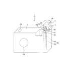
- FIG. 6 is a perspective view showing the biaxial rotating mechanism 6.
- the digital camera 1 includes a camera body 2 having an imaging lens 2a and a shutter button 2b, an electronic display (not shown) that displays an image captured by the imaging lens 2a, and an electronic viewfinder 3.
- the electronic display is a liquid crystal display (including LCOS), an organic EL display, or the like.
- the electronic viewfinder 3 can be accommodated in the camera body 2 and protrudes from the camera body 2 during shooting.
- the electronic viewfinder 3 includes an eyepiece 4 and an image display unit (not shown) that displays a captured image. The user visually recognizes the captured image displayed on the image display unit through the eyepiece 4.
- the camera body 2 and the electronic viewfinder 3 are electrically connected by wiring (not shown).
- a convex portion 3 b is provided on the front surface 3 a of the electronic viewfinder 3. The user can lift the electronic viewfinder 3 by picking up the convex portion 3b.
- a lid 3d is provided on the side surface 3c of the electronic viewfinder 3.
- the lid 3d is provided so as to protrude from the side surface 3c of the electronic viewfinder 3, and is disposed above a support column 51 and a cylinder 52 which will be described later in plan view.
- the digital camera 1 includes a guide mechanism 5 that guides the elevation of the electronic viewfinder 3 and a biaxial rotation mechanism 6 that can rotate the electronic viewfinder 3 in accordance with the vertical screen position or horizontal screen position of the digital camera 1. I have.
- the guide mechanism 5 includes a column portion 51, a cylinder portion 52, and a positioning portion 53.
- the support column 51 is formed in a cylindrical shape, and is set to a length corresponding to the elevation distance of the electronic viewfinder 3.
- the tapered portion 54 which is chamfered in a tapered shape is formed at the tip of the column portion 51, when the column portion 51 is attached to the cylindrical portion 52, the column portion 51 elastically deforms a stopper pin 53c described later.
- the column portion 51 can be smoothly inserted into the cylindrical portion 52.
- the cylindrical portion 52 is formed in a substantially cylindrical shape, and is set to a length that is approximately twice the elevation distance of the electronic viewfinder 3.
- a cutout portion 52 a is formed on the upper portion of the cylindrical portion 52.
- the notch 52a is formed so as not to interfere when the connecting portion 61 described later moves.
- On the peripheral surface of the cylindrical part 52 a notch part 52b corresponding to the diameter of a stopper pin 53c described later is formed.
- the notch 52b is formed using a key sheet cutter or the like.
- the positioning portion 53 includes a first stopper groove 53 a carved in the upper peripheral surface of the support column 51, a second stopper groove 53 b carved in the lower peripheral surface of the support column 51, and the camera body 2. And a stopper pin 53c provided.
- the first stopper groove 53 a is carved at a position where the stopper pin 53 c hits the support column 51 in the position (accommodation position) of the electronic viewfinder 3 when the electronic viewfinder 3 is accommodated in the camera body 2. .
- the first stopper groove 53a is formed by cutting out into a substantially rectangular shape in a side view.
- the second stopper groove 53a is engraved at a position where the stopper pin 53c hits the column 51 at the position (photographing position) of the electronic viewfinder 3 when the electronic viewfinder 3 protrudes from the camera body 2. Therefore, the second stopper groove 53b is disposed below the first stopper groove 53a, and the separation distance between the first stopper groove 53a and the second stopper groove 53b is equal to the elevation distance of the electronic viewfinder 3. Correspond.
- the second stopper groove 53b is cut out in a substantially rectangular shape in a side view, and the upper portion is chamfered in a tapered shape.
- the stopper pin 53c is a piano wire or the like extending in the horizontal direction, and is bonded to the camera body 2 in the vicinity of the tube portion 52. Note that the stopper pin 53c may be driven and coupled to the camera body 2. The stopper pin 53c can come into contact with the support column 51 via the notch 52b. When the stopper pin 53c is engaged with the first stopper groove 53a or the second stopper groove 53b, the column part 51 can be positioned with respect to the cylinder part 52.
- the radius of the stopper pin 53c By setting the radius of the stopper pin 53c to be larger than the depth of the first stopper groove 53a, the engagement between the stopper pin 53c and the first stopper groove 53a can be easily released by an external force in the vertical direction.
- the radius of the stopper pin 53c is set to be smaller than the depth of the second stopper groove 53b, and the upper portion of the first stopper groove 53b is formed in a tapered shape, so that the stopper can be stopped by an external force in the vertical direction.
- the engagement between the pin 53c and the second stopper groove 53b can be easily released.
- the depth of the second stopper groove 53b is set to be larger than the radius of the stopper pin 53c, the stopper pin 53c can be prevented from dropping below the second stopper groove 53b.
- the taper part 54 is formed at the tip of the column part 51, the electronic viewfinder 3 can be attached to the cylinder part 52 after being assembled to the column part 51 by the connecting part 61.
- the biaxial rotation mechanism 6 includes a connecting portion 61, a first shaft portion 62, and a second shaft portion 63.
- the connecting portion 61 is formed in a substantially L shape.
- the connecting portion 61 connects the electronic viewfinder 3 and the column portion 51 that are juxtaposed in plan view. Thereby, since the installation space of the spring arrange
- the connecting portion 61 includes a vertical surface portion 61a and a horizontal surface portion 61b.
- Reference numeral 64 is provided on the side surface 3 c of the electronic viewfinder 3, and is used when the electronic viewfinder 3 is accommodated in the camera body 2 in a state where the optical axis of the eyepiece lens 4 is aligned with the ascending / descending direction of the electronic viewfinder 3. This is a positioning protrusion for positioning the electronic viewfinder 3 at a predetermined position in contact with the connecting portion 61.
- a first hole 61c through which the first shaft portion 62 is inserted is formed in the vertical surface portion 61a.
- a second hole 61d through which the second shaft portion 63 is inserted is formed in the lateral surface portion 61b.
- the vertical surface portion 61a and the horizontal surface portion 61b are connected at a substantially right angle.
- the width of the horizontal surface portion 61b is preferably set to be equal to or less than the width of the support column portion 51. Thereby, it can suppress that the horizontal surface part 61b interferes with the cylinder part 52.
- the first shaft portion 62 rotatably supports the electronic viewfinder 3 with respect to the connecting portion 61.
- the rotation axis A of the first shaft portion 62 is set parallel to the longitudinal direction of the camera body 2.
- first direction the direction in which the electronic viewfinder 3 is rotated clockwise as viewed from the axis of the first shaft portion 62 is referred to as “first direction”.
- Reference numeral 65 denotes a reverse rotation restricting projection that restricts the electronic viewfinder 3 in response to the reverse rotation in the first direction.
- the second shaft portion 63 pivotally supports the connecting portion 61 with respect to the column portion 51.
- the rotation axis B of the second shaft portion 63 is set parallel to the short direction of the camera body 2.
- Reference numeral 66 denotes an over-rotation restricting protrusion that receives the electronic viewfinder 3 and restricts the rotation range of the connecting portion 61 in the second direction.
- FIG. 7 is a perspective view showing a state where the electronic viewfinder 3 is raised.
- FIG. 8 is a perspective view showing a state in which the electronic viewfinder 3 is rotated around the first shaft portion 62.
- FIG. 9 is a perspective view showing a state in which the connecting portion 61 is rotated around the second shaft portion 63.
- the lid portion 3 d of the electronic viewfinder 3 blocks the upper part of the column part 51 and the cylinder part 52. While the electronic viewfinder 3 is housed in the camera body 2, the stopper pin 53 c is engaged with the first stopper groove 53 a, and the electronic viewfinder 3 is prevented from popping out carelessly.
- the electronic viewfinder 3 When the electronic viewfinder 3 and the support column 51 are raised, the electronic viewfinder 3 protrudes from the camera body 2 as shown in FIG. Since the column portion 51 is surrounded by the cylindrical portion 52, the electronic viewfinder 3 is restricted from moving in the horizontal direction while the electronic viewfinder 3 is raised. When the electronic viewfinder 3 is raised by a predetermined distance, the stopper pin 53c is engaged with the second stopper groove 53b, and the electronic viewfinder 3 is positioned at the photographing position.
- the electronic viewfinder 3 when the electronic viewfinder 3 rotates approximately 90 degrees in the first direction, the electronic viewfinder 3 hits the camera body 2, and the optical axis of the imaging lens 2a and the optical axis of the eyepiece 4 are parallel to each other. Corresponding to the horizontal screen position of the digital camera 1. Note that the reverse rotation restricting protrusion 65 prevents the electronic viewfinder 3 from rotating in the direction opposite to the first direction.
- the electronic viewfinder 3 and the connecting portion 61 rotate approximately 90 degrees in the second direction, the electronic viewfinder 3 hits the over-rotation restricting projection 66, and the optical axis of the imaging lens 2a and the eyepiece 4 Are substantially orthogonal to each other and correspond to the vertical screen position of the digital camera 1.
- the guide mechanism 50 guides the lifting and lowering of the electronic viewfinder 3, and the biaxial rotation mechanism 60 moves the electronic viewfinder 3 to the first shaft portion 62 or the second shaft portion 62. It can be arbitrarily rotated around the shaft portion 63. That is, the electronic viewfinder 3 can correspond to the horizontal screen position by rotating the electronic viewfinder 3 relative to the connecting portion 61 in the first direction. In addition, the electronic viewfinder 3 can correspond to the vertical screen position by rotating the connecting portion 61 relative to the guide mechanism 50 in the second direction.
- the column portion 51 connected to the electronic viewfinder 3 is accommodated in the cylindrical portion 52 in a nested manner, the column portion 51 may be displaced in the horizontal direction when the electronic viewfinder 3 moves up and down. Since it is regulated, the electronic viewfinder 3 can be moved up and down accurately.
- the electronic viewfinder 3 can be arbitrarily positioned at the storage position or the photographing position.
- the rotation axis of the first shaft portion 62 is set parallel to the longitudinal direction of the camera body 2
- the rotation axis of the second shaft portion 63 is set parallel to the lateral direction of the camera body 2.
- the present invention is not limited to these structures, and the electronic viewfinder 3 is rotated about a rotation axis parallel to the short direction of the camera body 2, and the connecting portion 61 is rotated about a rotation axis parallel to the longitudinal direction of the camera body 2. You may make it the structure to rotate.
- rotation angle of the electronic viewfinder 3 and the connecting portion 61 is not limited to 90 degrees, and may be, for example, 80 degrees or 100 degrees.
- Second hole 62 ... First shaft 63 ... Second shaft 64 ... Positioning protrusion 65 ... Reverse rotation restricting protrusion 66. .. Over-rotation restricting protrusion A ... (of the first shaft Rotation axis B ⁇ ⁇ ⁇ (the second shaft portion) rotary shaft
Landscapes
- Physics & Mathematics (AREA)
- General Physics & Mathematics (AREA)
- Engineering & Computer Science (AREA)
- Multimedia (AREA)
- Signal Processing (AREA)
- Studio Devices (AREA)
- Viewfinders (AREA)
- Camera Bodies And Camera Details Or Accessories (AREA)
- Structure And Mechanism Of Cameras (AREA)
Abstract
【課題】ディジタルカメラの縦横の向きにかかわらず電子ビューファインダーを覗いて撮像画像を容易に確認可能なディジタルカメラを提供する。 【解決手段】ディジタルカメラ1は、撮像レンズ2aを有するカメラ本体2と、撮像レンズ2aによる撮像画像をユーザに観察させる電子ビューファインダー3と、電子ビューファインダー3の垂直昇降をガイドするガイド機構5と、電子ビューファインダー3を縦画面位置又は横画面位置に応じて回転可能な二軸回転機構6と、を備えている。二軸回転機構6は、電子ビューファインダー3とガイド機構5とを連結する連結部61と、電子ビューファインダー3を連結部61に対して第1の方向回りに回転可能に支持する第1の軸部62と、連結部61をガイド機構5に対して第2の方向回りに回転可能に支持する第2の軸部63と、を備えている。
Description
本発明は、ディジタルカメラに関するものであって、特に、電子ビューファインダーを縦横に回転自在なディジタルカメラを提供する。
従来より、ディジタルカメラでは、被写体の大きさ、向き等に応じて、撮像レンズの光軸を中心にカメラを回転させ、縦画面位置と横画面位置とを撮り分けられている。
撮像レンズの撮像画像をユーザに観察させる電子ビューファインダーを用いたディジタルカメラでは、ユーザが電子ビューファイダーの接眼レンズを通して撮像画像を視認して撮影を行う。特に、屋外等でディジタルカメラのディスプレイが視認し難い場合には、電子ビューファインダーを介して撮像画像を確認するのが一般的である。
特許文献1には、筐体に対して昇降自在に設けられたファインダーを備えたディジタルカメラが開示されている。このディジタルカメラを用いて撮影する場合には、ユーザがファインダースイッチを押すことにより、ファインダー保持フックとファインダー後方フックとの係合が解除され、ファインダースプリングによってファインダーが撮影可能な位置まで上昇する。そして、筐体に設けられたストッパーがファインダーを所定の位置に位置決めする。ユーザは、ファインダーを通して被写体を視認し、シャッタースイッチを押すことで撮影を行う。
しかしながら、上述したようなディジタルカメラは、ファインダーは、ファインダースプリングの付製方向に一致する筐体の長手方向に対して昇降するのみで、横画面位置の撮影に対応するものであり、縦画面位置の撮影には対応しないという問題があった。
そこで、ディジタルカメラの縦横の向きにかかわらず電子ビューファインダーを覗いて撮像画像を容易に確認するために解決すべき技術的課題が生じてくるのであり、本発明は、この課題を解決することを目的とする。
本発明は上記目的を達成するために提案されたものであり、請求項1記載の発明は、撮像レンズを有するカメラ本体と、該カメラ本体に昇降自在に収容可能で前記撮像レンズによる撮像画像をユーザに観察させる電子ビューファインダーと、を備えるディジタルカメラにおいて、前記電子ビューファインダーの昇降をガイドするガイド機構と、前記電子ビューファインダーと前記ガイド機構とを連結する連結部と、前記電子ビューファインダーを前記連結部に対して第1の方向回りに回転可能に支持する第1の軸部と、前記連結部を前記ガイド機構に対して前記第1の方向に垂直な第2の方向回りに回転可能に支持する第2の軸部と、を有する2軸回転機構と、を備えているディジタルカメラを提供する。
この構成によれば、ガイド機構が電子ビューファインダーの昇降をガイドし、二軸回転機構が電子ビューファインダーを第1の軸部又は第2の軸部回りに任意に回転させることができる。すなわち、電子ビューファインダーが連結部に対して第1の方向に相対的に回することにより、電子ビューファインダーは、縦画面位置又は横画面位置の何れか一方に対応することができる。また、連結部がガイド機構に対して第2の方向に相対的に回転することにより、電子ビューファインダーは、縦画面位置又は横画面位置の他方に対応することができる。
請求項2記載の発明は、請求項1記載のディジタルカメラの構成に加えて、前記ガイド機構は、前記連結部を介して前記電子ビューファインダーに連結された支柱部と、前記カメラ本体に設けられ、前記支柱部を昇降可能に入れ子状で収容する筒部と、前記電子ビューファインダーが前記カメラ本体に収容された収容位置又は前記電子ビューファインダーが前記カメラ本体から突出した撮影位置に応じて、前記支柱部を位置決め可能な位置決め部と、を備えているディジタルカメラを提供する。
この構成によれば、電子ビューファインダーに連結された支柱部が筒部に入れ子状に収容されていることにより、電子ビューファインダーが昇降する際に、支柱部が水平方向に位置ズレすることが規制されているため、電子ビューファインダーを正確に昇降させることができる。
請求項3記載の発明は、請求項2記載のディジタルカメラの構成に加えて、前記位置決め部は、前記支柱部の周面に前記収容位置に応じて刻設された第1のストッパ溝と、前記支柱部の周面に前記撮影位置に応じて刻設された第2のストッパ溝と、前記第1のストッパ溝又は第2のストッパ溝に係合可能なストッパピンと、を備えているディジタルカメラを提供する。
この構成によれば、ストッパピンを第1のストッパ溝又は第2のストッパ溝に係合させることにより、電子ビューファインダーを収容位置又は撮影位置で任意に位置決めすることができる。
請求項4記載の発明は、請求項1乃至3の何れか1項記載のディジタルカメラの構成に加えて、前記第1の方向における前記電子ビューファインダーの逆回転を規制する逆回転規制部を備えているディジタルカメラを提供する。
この構成によれば、逆回転規制部が電子ビューファインダーの逆回転を規制するため、電子ビューファインダーの位置調整を容易に行うことができる。
請求項5記載の発明は、請求項1乃至4の何れか1項記載のディジタルカメラの構成に加えて、前記第2の方向における前記連結部の回転範囲を規制する過回転規制部を備えているディジタルカメラを提供する。
この構成によれば、過回転規制部が連結部の回転範囲を規制することにより、連結部の回り過ぎが抑制されるため、電子ビューファインダーの位置調整を容易に行うことができる。
請求項6記載の発明は、請求項1乃至5の何れか1項記載のディジタルカメラの構成に加えて、前記連結部は、前記第1の軸部が挿通される第1の孔部が形成されて前記電子ビューファインダーに対向する縦面部と、前記第2の軸部が挿通される第2の孔部が形成されて前記支柱部に対向する横面部と、を略L字状に配置してなるディジタルカメラを提供する。
この構成によれば、略L字状に形成された連結部を用いて電子ビューファインダーと支柱部とが平面視で並んで配置されていることにより、従来のような電子ビューファインダーの下方に配置されたスプリングの設置スペースが省略されるため、カメラ本体を小型化することができる。
本発明は、電子ビューファインダーが連結部に対して第1の方向に相対的に回転することにより、電子ビューファインダーは、縦画面位置又は横画面位置の何れか一方に対応することができる。また、連結部がガイド機構に対して第2の方向に相対的に回転することにより、電子ビューファインダーは、縦画面位置又は横画面位置の他方に対応することができる。
本発明は、ディジタルカメラの縦横の向きにかかわらず電子ビューファインダーを覗いて撮像画像を容易に確認するという目的を達成するために、撮像レンズを有するカメラ本体と、カメラ本体に昇降自在に収容可能で撮像レンズによる撮像画像をユーザに観察させる電子ビューファインダーと、を備えるディジタルカメラにおいて、電子ビューファインダーの昇降をガイドするガイド機構と、電子ビューファインダーとガイド機構とを連結する連結部と、電子ビューファインダーを連結部に対して第1の方向回りに回転可能に支持する第1の軸部と、連結部をガイド機構に対して第1の方向に垂直な第2の方向回りに回転可能に支持する第2の軸部と、を有する二軸回転機構と、を備えていることにより実現した。
以下、本発明の一実施例に係るディジタルカメラ1について、図面に基づいて説明する。図1は、ディジタルカメラ1を示す斜視図である。図2は、ディジタルカメラ1の一部切欠斜視図である。図3は、蓋部3dを省略したディジタルカメラ1の平面図である。図4は、位置決め部53を示す模式図である。図5(a)は、第1のストッパ溝53aにストッパピン53cが係合している様子を示す側面図である。図5(b)は、第2のストッパ溝53bにストッパピン53cが係合している様子を示す側面図である図6は、二軸回転機構6を示す斜視図。
本実施例に係るディジタルカメラ1は、撮像レンズ2a及びシャッターボタン2bを有するカメラ本体2と、撮像レンズ2aによる撮像画像を表示する図示しない電子ディスプレイと、電子ビューファインダー3と、を備えている。なお、電子ディスプレイは、液晶ディスプレイ(LCOSを含む)、有機ELディスプレイ等である。
電子ビューファインダー3は、カメラ本体2内に収容可能であり、撮影時にはカメラ本体2から突出する。電子ビューファインダー3は、接眼レンズ4と、撮像画像を表示する図示しない画像表示部と、を備えている。ユーザは、接眼レンズ4を通して画像表示部に表示された撮像画像を視認する。カメラ本体2と電子ビューファインダー3とは、図示しない配線によって電気的に接続されている。
電子ビューファインダー3の正面3aには、凸部3bが設けられている。ユーザは、凸部3bを摘まんで電子ビューファインダー3を昇降させることができる。
電子ビューファインダー3の側面3cには、蓋部3dが設けられている。蓋部3dは、電子ビューファインダー3の側面3cから突設されており、平面視で後述する支柱部51及び筒部52の上方に配置されている。
ディジタルカメラ1は、電子ビューファインダー3の昇降をガイドするガイド機構5と、ディジタルカメラ1の縦画面位置又は横画面位置に対応して電子ビューファインダー3を回転可能な二軸回転機構6と、を備えている。
ガイド機構5は、支柱部51と、筒部52と、位置決め部53と、を備えている。
支柱部51は、円柱状に形成されており、電子ビューファインダー3の昇降距離に応じた長さに設定されている。また、支柱部51の先端にテーパ―状に面取りされたテーパ部54が形成されていることにより、支柱部51を筒部52に取り付ける際に、支柱部51が後述するストッパピン53cを弾性変形させて支柱部51を筒部52にスムーズに挿通することができる。
筒部52は、略円筒状に形成されており、電子ビューファインダー3の昇降距離の略2倍の長さに設定されている。筒部52の上部には、切り欠き部52aが形成されている。切り欠き部52aは、後述する連結部61が移動する際に干渉しないように形成されたものである。筒部52の周面には、後述するストッパピン53cの直径に応じた切り欠き部52bが形成されている。切り欠き部52bは、キーシートカッター等を用いて形成される。
位置決め部53は、支柱部51の上部周面に刻設された第1のストッパ溝53aと、支柱部51の下部周面に刻設された第2のストッパ溝53bと、カメラ本体2内に設けられたストッパピン53cと、で構成されている。
第1のストッパ溝53aは、電子ビューファインダー3がカメラ本体2内に収容されたときの電子ビューファインダー3の位置(収容位置)において、ストッパピン53cが支柱部51に当たる位置に刻設されている。第1のストッパ溝53aは、側面視で略矩形状に切り欠いて形成されている。
第2のストッパ溝53aは、電子ビューファインダー3がカメラ本体2から突出した際の電子ビューファインダー3の位置(撮影位置)において、ストッパピン53cが支柱部51に当たる位置に刻設されている。したがって、第2のストッパ溝53bは、第1のストッパ溝53aより下方に配置されおり、第1のストッパ溝53aと第2のストッパ溝53bとの離間距離は、電子ビューファインダー3の昇降距離に対応する。第2のストッパ溝53bは、側面視で略矩形状に切り欠かれていると共に、上部をテーパ―状に面取りされている。
ストッパピン53cは、水平方向に延伸したピアノ線等であり、筒部52の近傍でカメラ本体2に接着されている。なお、ストッパピン53cは、カメラ本体2に打ち込まれて結合されたものであっても構わない。ストッパピン53cは、切り欠き部52bを介して支柱部51に接触可能である。ストッパピン53cが第1のストッパ溝53a又は第2のストッパ溝53bに係合することにより、支柱部51を筒部52に対して位置決めすることができる。
ストッパピン53cの半径を、第1のストッパ溝53aの深さより大きく設定することにより、垂直方向の外力によってストッパピン53cと第1のストッパ溝53aとの係合を容易に解除することができる。
また、ストッパピン53cの半径を、第2のストッパ溝53bの深さより小さく設定し、且つ、第1のストッパ溝53bの上部がテーパ―状に形成されていることにより、垂直方向の外力によってストッパピン53cと第2のストッパ溝53bとの係合を容易に解除することができる。さらに、ストッパピン53cの半径に対して、第2のストッパ溝53bの深さを、より大きく設定することにより、ストッパピン53cが第2のストッパ溝53bよりも下方に脱落することが抑制される。なお、支柱部51の先端にテーパ部54が形成されていることにより、電子ビューファインダー3を連結部61にて、支柱部51に組み付け後、筒部52に取り付けることができる。
二軸回転機構6は、連結部61と、第1の軸部62と、第2の軸部63と、を備えている。
連結部61は、略L字状に形成されている。連結部61は、平面視で並設された電子ビューファインダー3と支柱部51とを連結している。これにより、従来のような電子ビューファインダーの下方に配置されたスプリングの設置スペースが省略されるため、カメラ本体2を小型化することができる。連結部61は、縦面部61aと、横面部61bと、を備えている。なお、符号64は、電子ビューファインダー3の側面3cに設けられ、接眼レンズ4の光軸を電子ビューファインダー3の昇降方向に一致させた状態で電子ビューファインダー3をカメラ本体2に収容する際に、連結部61に当接して電子ビューファインダー3を所定の位置で位置決めするための位置決め突部である。
縦面部61aには、第1の軸部62が挿通される第1の孔部61cが形成されている。横面部61bには、第2の軸部63が挿通される第2の孔部61dが形成されている。縦面部61aと横面部61bとは、略直角に連結されている。横面部61bの幅は、支柱部51の幅と同じかそれ以下に設定されるのが好ましい。これにより、横面部61bが筒部52に干渉することを抑制できる。
第1の軸部62は、電子ビューファインダー3を連結部61に対して回転可能に軸支する。第1の軸部62の回転軸Aは、カメラ本体2の長手方向と平行に設定されている。以下、第1の軸部62の軸線から視て電子ビューファインダー3を時計回りに回転させる方向を「第1の方向」と称す。符号65は、第1の方向における電子ビューファインダー3の逆回転を受けて規制する逆回転規制突部である。
第2の軸部63は、連結部61を支柱部51に対して回転可能に軸支する。第2の軸部63の回転軸Bは、カメラ本体2の短手方向と平行に設定されている。以下、第2の軸部53の軸線から視て連結部61を時計回りに回転させる方向を「第2の方向」と称す。符号66は、電子ビューファインダー3を受けて、第2の方向における連結部61の回転範囲を規制する過回転規制突部である。
次に、電子ビューファインダー3の作用について、図面に基づいて説明する。図7は、電子ビューファインダー3が上昇した状態を示す斜視図である。図8は、電子ビューファインダー3を第1の軸部62回りに回転させた状態を示す斜視図である。図9は、連結部61を第2の軸部63回りに回転させた状態を示す斜視図である。
図1に示すように、カメラ本体2内に収容された電子ビューファインダー3は、電子ビューファインダー3の蓋部3dが、支柱部51及び筒部52の上方を塞いでいる。電子ビューファインダー3がカメラ本体2に収容されている間は、ストッパピン53cが第1のストッパ溝53aに係合し、電子ビューファインダー3が不用意に飛び出すことが防止されている。
電子ビューファインダー3及び支柱部51が上昇すると、図7に示すように、電子ビューファインダー3がカメラ本体2から突出する。支柱部51が筒部52に囲繞されるため、電子ビューファインダー3が上昇する間に水平方向に移動することが規制される。電子ビューファインダー3が所定距離だけ上昇すると、ストッパピン53cが第2のストッパ溝53bに係合し、電子ビューファインダー3が撮影位置に位置決めされる。
図8に示すように、電子ビューファインダー3が第1の方向に略90度回転すると、電子ビューファインダー3がカメラ本体2に当たり、撮像レンズ2aの光軸と接眼レンズ4の光軸とが平行になり、ディジタルカメラ1の横画面位置に対応する。なお、電子ビューファインダー3が第1の方向と逆向きに回転することは、逆回転規制突部65によって抑制されている。
図9に示すように、電子ビューファインダー3及び連結部61が第2の方向に略90度回転すると、電子ビューファインダー3が過回転規制突部66に当たり、撮像レンズ2aの光軸と接眼レンズ4の光軸とが略直交し、ディジタルカメラ1の縦画面位置に対応する。
上述したように、本実施例に係るディジタルカメラ1は、ガイド機構50が電子ビューファインダー3の昇降をガイドし、二軸回転機構60が電子ビューファインダー3を第1の軸部62又は第2の軸部63回りに任意に回転させることができる。すなわち、電子ビューファインダー3が連結部61に対して第1の方向に相対的に回転することにより、電子ビューファインダー3は、横画面位置に対応することができる。また、連結部61がガイド機構50に対して第2の方向に相対的に回転することにより、電子ビューファインダー3は、縦画面位置に対応することができる。
また、電子ビューファインダー3に連結された支柱部51が筒部52に入れ子状に収容されていることにより、電子ビューファインダー3が昇降する際に、支柱部51が水平方向に位置ズレすることが規制されているため、電子ビューファインダー3を正確に昇降させることができる。
さらに、ストッパピン53cを第1のストッパ溝53a又は第2のストッパ溝53bに係合させることにより、電子ビューファインダー3を収容位置又は撮影位置で任意に位置決めすることができる。
上述した実施例においては、カメラ本体2の長手方向と平行に第1の軸部62の回転軸を設定し、カメラ本体2の短手方向と平行に第2の軸部63の回転軸を設定したが、これらの構造に限定されず、電子ビューファインダー3をカメラ本体2の短手方向と平行な回転軸回りに回転させ、連結部61をカメラ本体2の長手方向と平行な回転軸回りに回転させる構造にしても構わない。
なお、電子ビューファインダー3及び連結部61の回転角度は90度に限定されず、例えば、80度や100度であっても構わない。
なお、本発明は、本発明の精神を逸脱しない限り種々の改変をなすことができ、そして、本発明が該改変されたものにも及ぶことは当然である。
1 ・・・ ディジタルカメラ
2 ・・・ カメラ本体
2a・・・ 撮像レンズ
2b・・・ シャッターボタン
3 ・・・ 電子ビューファイダー
3a・・・ 正面
3b・・・ 凸部
3c・・・ 側面
3d・・・ 蓋部
4 ・・・ 接眼レンズ
5 ・・・ ガイド機構
51・・・ 支柱部
52・・・ 筒部
52a・・・切り欠き部
53・・・ 位置決め部
53a・・・第1のストッパ溝
53b・・・第2のストッパ溝
53c・・・ストッパピン
54・・・ テーパ部
6 ・・・ 二軸回転機構
61・・・ 連結部
61a・・・縦面部
61b・・・横面部
61c・・・第1の孔部
61d・・・第2の孔部
62・・・ 第1の軸部
63・・・ 第2の軸部
64・・・ 位置決め突部
65・・・ 逆回転規制突部
66・・・ 過回転規制突部
A ・・・ (第1の軸部の)回転軸
B ・・・ (第2の軸部の)回転軸
Claims (6)
- 撮像レンズを有するカメラ本体と、該カメラ本体に昇降自在に収容可能で前記撮像レンズによる撮像画像をユーザに観察させる電子ビューファインダーと、を備えるディジタルカメラにおいて、
前記電子ビューファインダーの昇降をガイドするガイド機構と、
前記電子ビューファインダーと前記ガイド機構とを連結する連結部と、前記電子ビューファインダーを前記連結部に対して第1の方向回りに回転可能に支持する第1の軸部と、前記連結部を前記ガイド機構に対して前記第1の方向に垂直な第2の方向回りに回転可能に支持する第2の軸部と、を有する二軸回転機構と、を備えていることを特徴とするディジタルカメラ。 - 前記ガイド機構は、
前記連結部を介して前記電子ビューファインダーに連結された支柱部と、
前記カメラ本体に設けられ、前記支柱部を昇降可能に入れ子状で収容する筒部と、
前記電子ビューファインダーが前記カメラ本体に収容された収容位置又は前記電子ビューファインダーが前記カメラ本体から突出した撮影位置に応じて、前記支柱部を位置決め可能な位置決め部と、を備えていることを特徴とする請求項1記載のディジタルカメラ。 - 前記位置決め部は、
前記支柱部の周面に前記収容位置に応じて刻設された第1のストッパ溝と、
前記支柱部の周面に前記撮影位置に応じて刻設された第2のストッパ溝と、
前記第1のストッパ溝又は第2のストッパ溝に係合可能なストッパピンと、を備えていることを特徴とする請求項2記載のディジタルカメラ。 - 前記第1の方向における前記電子ビューファインダーの逆回転を規制する逆回転規制部を備えていることを特徴とする請求項1乃至3の何れか1項記載のディジタルカメラ。
- 前記第2の方向における前記連結部の回転範囲を規制する過回転規制部を備えていることを特徴とする請求項1乃至4の何れか1項記載のディジタルカメラ。
- 前記連結部は、前記第1の軸部が挿通される第1の孔部が形成されて前記電子ビューファインダーに対向する縦面部と、前記第2の軸部が挿通される第2の孔部が形成されて前記支柱部に対向する横面部と、を略L字状に配置してなることを特徴とする請求項1乃至5の何れか1項記載のディジタルカメラ。
Priority Applications (3)
| Application Number | Priority Date | Filing Date | Title |
|---|---|---|---|
| CN201680066025.9A CN108351575B (zh) | 2015-11-11 | 2016-10-19 | 数字照相机 |
| US15/774,732 US10459314B2 (en) | 2015-11-11 | 2016-10-19 | Digital camera |
| EP16863969.8A EP3376283B1 (en) | 2015-11-11 | 2016-10-19 | Digital camera |
Applications Claiming Priority (2)
| Application Number | Priority Date | Filing Date | Title |
|---|---|---|---|
| JP2015220965A JP5913718B1 (ja) | 2015-11-11 | 2015-11-11 | ディジタルカメラ |
| JP2015-220965 | 2015-11-11 |
Publications (1)
| Publication Number | Publication Date |
|---|---|
| WO2017082005A1 true WO2017082005A1 (ja) | 2017-05-18 |
Family
ID=55808295
Family Applications (1)
| Application Number | Title | Priority Date | Filing Date |
|---|---|---|---|
| PCT/JP2016/080924 WO2017082005A1 (ja) | 2015-11-11 | 2016-10-19 | ディジタルカメラ |
Country Status (6)
| Country | Link |
|---|---|
| US (1) | US10459314B2 (ja) |
| EP (1) | EP3376283B1 (ja) |
| JP (1) | JP5913718B1 (ja) |
| CN (1) | CN108351575B (ja) |
| TW (1) | TWI608285B (ja) |
| WO (1) | WO2017082005A1 (ja) |
Families Citing this family (3)
| Publication number | Priority date | Publication date | Assignee | Title |
|---|---|---|---|---|
| JP5913718B1 (ja) * | 2015-11-11 | 2016-04-27 | 稔 稲葉 | ディジタルカメラ |
| JP7292888B2 (ja) * | 2019-01-31 | 2023-06-19 | キヤノン株式会社 | 撮像装置 |
| JP7475986B2 (ja) * | 2020-06-25 | 2024-04-30 | キヤノン株式会社 | 電子機器 |
Citations (6)
| Publication number | Priority date | Publication date | Assignee | Title |
|---|---|---|---|---|
| JPS6261035A (ja) * | 1985-09-12 | 1987-03-17 | Matsushita Electric Ind Co Ltd | ビデオカメラ |
| JPH0449782A (ja) * | 1990-06-18 | 1992-02-19 | Sharp Corp | ビデオカメラのビューファインダ |
| JPH0590093U (ja) * | 1991-09-04 | 1993-12-07 | 敏一 大松 | カメラ用三脚における回り止め脚伸縮固定装置 |
| JP2000188704A (ja) * | 1998-12-22 | 2000-07-04 | Sony Corp | ビデオカメラ |
| JP2006081216A (ja) * | 2005-11-07 | 2006-03-23 | Sony Corp | ビデオカメラ |
| JP2014023075A (ja) * | 2012-07-23 | 2014-02-03 | Astro Design Inc | ビューファインダ支持装置 |
Family Cites Families (21)
| Publication number | Priority date | Publication date | Assignee | Title |
|---|---|---|---|---|
| US5548334A (en) * | 1990-01-11 | 1996-08-20 | Canon Kabushiki Kaisha | Video camera having viewfinder rotatably mounted on camera body |
| JP2748653B2 (ja) * | 1990-05-25 | 1998-05-13 | ソニー株式会社 | カメラ一体型vtr |
| US5321456A (en) * | 1992-04-21 | 1994-06-14 | Daewoo Electronics Co., Ltd. | Detachable view finder for video camera |
| JPH08125890A (ja) * | 1994-10-21 | 1996-05-17 | Sony Corp | ビデオカメラ |
| JPH09138438A (ja) * | 1995-11-10 | 1997-05-27 | Sony Corp | ビデオカメラ |
| JPH10142666A (ja) | 1996-11-15 | 1998-05-29 | Matsushita Electric Ind Co Ltd | デジタルカメラ |
| US20020067426A1 (en) * | 1997-04-10 | 2002-06-06 | Hideki Nagata | Electronic camera having a phoelectric sensor device |
| JPH11355618A (ja) * | 1998-06-05 | 1999-12-24 | Fuji Photo Film Co Ltd | 電子ビューファインダー |
| US7046287B2 (en) * | 1999-12-24 | 2006-05-16 | Nec Corporation | Portable information terminal equipped with camera |
| JP2004221894A (ja) * | 2003-01-14 | 2004-08-05 | Sharp Corp | ビデオカメラ |
| JP4282420B2 (ja) * | 2003-09-22 | 2009-06-24 | オリンパス株式会社 | カメラ |
| JP2006135765A (ja) * | 2004-11-08 | 2006-05-25 | Fuji Photo Film Co Ltd | 撮影装置 |
| JP5560341B2 (ja) * | 2010-09-17 | 2014-07-23 | 富士フイルム株式会社 | デジタルカメラ及びそのファインダ装置 |
| JP5456081B2 (ja) * | 2012-02-03 | 2014-03-26 | キヤノン株式会社 | カメラ |
| JP6132430B2 (ja) * | 2013-04-04 | 2017-05-24 | 三星電子株式会社Samsung Electronics Co.,Ltd. | カメラ装置及びそれを備えた無線通信端末 |
| US9413968B2 (en) * | 2013-04-04 | 2016-08-09 | Samsung Electronics Co., Ltd. | Camera apparatus and wireless communication terminal including the same |
| JP2014206626A (ja) * | 2013-04-12 | 2014-10-30 | 株式会社ニコン | 電子機器および撮像装置 |
| KR20150014320A (ko) * | 2013-07-29 | 2015-02-06 | 삼성전자주식회사 | 전자식 뷰파인더 장치 및 촬상 장치 |
| TWM469694U (zh) * | 2013-08-06 | 2014-01-01 | Pegatron Corp | 具光學觀景窗的手機 |
| JP5848484B1 (ja) * | 2015-07-24 | 2016-01-27 | 稔 稲葉 | ディジタルカメラ |
| JP5913718B1 (ja) * | 2015-11-11 | 2016-04-27 | 稔 稲葉 | ディジタルカメラ |
-
2015
- 2015-11-11 JP JP2015220965A patent/JP5913718B1/ja not_active Expired - Fee Related
-
2016
- 2016-10-19 US US15/774,732 patent/US10459314B2/en not_active Expired - Fee Related
- 2016-10-19 EP EP16863969.8A patent/EP3376283B1/en active Active
- 2016-10-19 WO PCT/JP2016/080924 patent/WO2017082005A1/ja active Application Filing
- 2016-10-19 TW TW105133958A patent/TWI608285B/zh not_active IP Right Cessation
- 2016-10-19 CN CN201680066025.9A patent/CN108351575B/zh not_active Expired - Fee Related
Patent Citations (6)
| Publication number | Priority date | Publication date | Assignee | Title |
|---|---|---|---|---|
| JPS6261035A (ja) * | 1985-09-12 | 1987-03-17 | Matsushita Electric Ind Co Ltd | ビデオカメラ |
| JPH0449782A (ja) * | 1990-06-18 | 1992-02-19 | Sharp Corp | ビデオカメラのビューファインダ |
| JPH0590093U (ja) * | 1991-09-04 | 1993-12-07 | 敏一 大松 | カメラ用三脚における回り止め脚伸縮固定装置 |
| JP2000188704A (ja) * | 1998-12-22 | 2000-07-04 | Sony Corp | ビデオカメラ |
| JP2006081216A (ja) * | 2005-11-07 | 2006-03-23 | Sony Corp | ビデオカメラ |
| JP2014023075A (ja) * | 2012-07-23 | 2014-02-03 | Astro Design Inc | ビューファインダ支持装置 |
Non-Patent Citations (1)
| Title |
|---|
| See also references of EP3376283A4 * |
Also Published As
| Publication number | Publication date |
|---|---|
| US10459314B2 (en) | 2019-10-29 |
| CN108351575A (zh) | 2018-07-31 |
| TWI608285B (zh) | 2017-12-11 |
| EP3376283A9 (en) | 2020-06-10 |
| EP3376283B1 (en) | 2020-09-23 |
| US20190025670A1 (en) | 2019-01-24 |
| JP5913718B1 (ja) | 2016-04-27 |
| EP3376283A4 (en) | 2019-04-03 |
| JP2017090696A (ja) | 2017-05-25 |
| EP3376283A1 (en) | 2018-09-19 |
| CN108351575B (zh) | 2020-11-27 |
| TW201728986A (zh) | 2017-08-16 |
Similar Documents
| Publication | Publication Date | Title |
|---|---|---|
| WO2017082005A1 (ja) | ディジタルカメラ | |
| US9435990B2 (en) | Upright and inverted microscope | |
| WO2010029727A1 (ja) | ドーム型カメラ | |
| CN105430131B (zh) | 一种手机的角度可调式摄像头组件及手机 | |
| JP2006337882A (ja) | 撮像装置 | |
| US20110286119A1 (en) | Lens barrel, imaging device and manufacturing method thereof | |
| JP2010183420A (ja) | 撮像装置 | |
| JP2011175127A (ja) | 電子機器 | |
| US20140300715A1 (en) | Image magnifying apparatus | |
| US9989748B1 (en) | Upright and inverted microscope | |
| EP3328053B1 (en) | Digital camera | |
| CN113395851B (zh) | 一种计算机视觉防护装置及其使用方法 | |
| JP4391882B2 (ja) | 回動軸構造及びカメラのグリップ回動軸構造 | |
| JP5669653B2 (ja) | 資料撮像装置 | |
| JP5461739B1 (ja) | ディジタルカメラ | |
| JP2005326515A (ja) | カメラのグリップ回動進退軸構造及び回動進退軸構造 | |
| JP2011203408A (ja) | レンズシフト機構、プロジェクタ | |
| JP2017098722A (ja) | 電子機器 | |
| JP5420107B1 (ja) | ディジタルカメラ | |
| CN213024858U (zh) | 一种视觉传达专业教学用演示装置 | |
| JP4429072B2 (ja) | カメラの基板接続構造 | |
| TWI596381B (zh) | Stereo viewfinder and / or stereo viewfinder | |
| KR101417814B1 (ko) | 디지털 촬영장치 | |
| JP2009261015A (ja) | ビデオカメラ | |
| JP2013156532A (ja) | レンズ鏡筒、及び撮像装置 |
Legal Events
| Date | Code | Title | Description |
|---|---|---|---|
| 121 | Ep: the epo has been informed by wipo that ep was designated in this application |
Ref document number: 16863969 Country of ref document: EP Kind code of ref document: A1 |
|
| NENP | Non-entry into the national phase |
Ref country code: DE |
|
| WWE | Wipo information: entry into national phase |
Ref document number: 2016863969 Country of ref document: EP |