WO2013172152A1 - 手術支援装置 - Google Patents
手術支援装置 Download PDFInfo
- Publication number
- WO2013172152A1 WO2013172152A1 PCT/JP2013/061747 JP2013061747W WO2013172152A1 WO 2013172152 A1 WO2013172152 A1 WO 2013172152A1 JP 2013061747 W JP2013061747 W JP 2013061747W WO 2013172152 A1 WO2013172152 A1 WO 2013172152A1
- Authority
- WO
- WIPO (PCT)
- Prior art keywords
- unit
- treatment
- surgical
- information
- detection device
- Prior art date
Links
Images

Classifications
-
- A—HUMAN NECESSITIES
- A61—MEDICAL OR VETERINARY SCIENCE; HYGIENE
- A61B—DIAGNOSIS; SURGERY; IDENTIFICATION
- A61B34/00—Computer-aided surgery; Manipulators or robots specially adapted for use in surgery
- A61B34/30—Surgical robots
-
- A—HUMAN NECESSITIES
- A61—MEDICAL OR VETERINARY SCIENCE; HYGIENE
- A61B—DIAGNOSIS; SURGERY; IDENTIFICATION
- A61B34/00—Computer-aided surgery; Manipulators or robots specially adapted for use in surgery
- A61B34/70—Manipulators specially adapted for use in surgery
-
- A—HUMAN NECESSITIES
- A61—MEDICAL OR VETERINARY SCIENCE; HYGIENE
- A61B—DIAGNOSIS; SURGERY; IDENTIFICATION
- A61B34/00—Computer-aided surgery; Manipulators or robots specially adapted for use in surgery
- A61B34/20—Surgical navigation systems; Devices for tracking or guiding surgical instruments, e.g. for frameless stereotaxis
- A61B2034/2046—Tracking techniques
- A61B2034/2055—Optical tracking systems
-
- A—HUMAN NECESSITIES
- A61—MEDICAL OR VETERINARY SCIENCE; HYGIENE
- A61B—DIAGNOSIS; SURGERY; IDENTIFICATION
- A61B34/00—Computer-aided surgery; Manipulators or robots specially adapted for use in surgery
- A61B34/30—Surgical robots
- A61B2034/301—Surgical robots for introducing or steering flexible instruments inserted into the body, e.g. catheters or endoscopes
-
- A—HUMAN NECESSITIES
- A61—MEDICAL OR VETERINARY SCIENCE; HYGIENE
- A61B—DIAGNOSIS; SURGERY; IDENTIFICATION
- A61B90/00—Instruments, implements or accessories specially adapted for surgery or diagnosis and not covered by any of the groups A61B1/00 - A61B50/00, e.g. for luxation treatment or for protecting wound edges
- A61B90/06—Measuring instruments not otherwise provided for
- A61B2090/067—Measuring instruments not otherwise provided for for measuring angles
-
- A—HUMAN NECESSITIES
- A61—MEDICAL OR VETERINARY SCIENCE; HYGIENE
- A61B—DIAGNOSIS; SURGERY; IDENTIFICATION
- A61B90/00—Instruments, implements or accessories specially adapted for surgery or diagnosis and not covered by any of the groups A61B1/00 - A61B50/00, e.g. for luxation treatment or for protecting wound edges
- A61B90/39—Markers, e.g. radio-opaque or breast lesions markers
- A61B2090/3983—Reference marker arrangements for use with image guided surgery
Definitions
- the present invention relates to a surgical operation support apparatus operated by remote control.
- This application claims priority based on Japanese Patent Application No. 2012-114484 filed in Japan on May 18, 2012, the contents of which are incorporated herein by reference.
- an electric endoscope including a treatment instrument channel into which a treatment instrument is inserted is known as a medical instrument used for surgery (see, for example, Patent Document 1).
- the medical instrument described in Patent Literature 1 can be operated by bending a bending portion of an electric endoscope using a joystick and inserting various treatment tools into a treatment tool channel. It is configured.
- the present invention has been made in view of the above-described circumstances, and an object thereof is to provide a surgical operation support device that can be operated intuitively and easily by an operator.
- the surgery support apparatus includes an operation input unit that issues an operation command based on an input from a user, and an operation unit that is attached with a surgical tool and operates the surgical tool based on the operation command.
- the surgical instrument comprises: a treatment section that performs a treatment on a treatment target; a long flexible insertion section provided with one end of the treatment section; and the flexible insertion And an operation part fixed to the treatment part and connected to the treatment part.
- the operation input unit includes a detection target attached to the operation unit of the surgical instrument and a detection device that detects the detection target.
- the detection device calculates information that can specify at least one of the position and orientation of the detected object.
- the operation input unit controls the operation of the surgical instrument by outputting a command for moving the surgical tool as the operation command to the operating unit based on the information calculated by the detection device.
- the detected object includes a main body part attached to the operation part and a marker provided on the main body part. May be.
- the detection device may calculate the information using the marker.
- the detection device is based on an origin set so as to have a predetermined positional relationship with the operation unit.
- the information may be calculated using a coordinate system.
- the detected object includes a labeling unit that allows the detection device to identify the surgical tool. Also good.
- the detection device may recognize the marker unit, identify the surgical tool and other surgical tools, and set an origin of a coordinate system for calculating the information according to the marker unit. .
- the operation unit controls at least one of a position and a posture based on the operation command.
- You may have a slave arm.
- the slave arm may have a hollow portion into which the flexible insertion portion is inserted and opened at a distal end portion of the slave arm.
- the treatment portion may protrude from an opening provided at a distal end portion of the hollow portion.
- the operation unit controls at least one of a position and a posture based on the operation command.
- You may have a treatment part moving mechanism to move.
- the detected object may include an adapter attached to the operation unit.
- the detection device may include a multi-joint arm connected to the adapter, and a position and orientation detection unit that detects the position and posture of the multi-joint arm and outputs the information as the information.
- the detected object may be sterilizable.
- the detected object may be attached to the operation unit via a sterilizable member.
- the operator can operate the surgery support apparatus intuitively and easily.
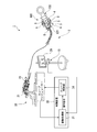
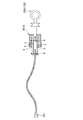
- FIG. 1 is an overall view showing a surgery support apparatus according to a first embodiment of the present invention. It is a schematic diagram of the surgical instrument used with the surgery assistance apparatus of 1st Embodiment of this invention. It is a block diagram of the detection apparatus in the surgery assistance apparatus of 1st Embodiment of this invention. It is a schematic diagram which shows a part of slave manipulator in the surgery assistance apparatus of 1st Embodiment of this invention. It is a block diagram of the control apparatus and slave arm in the surgery assistance apparatus of 1st Embodiment of this invention. It is a schematic diagram which shows the operation
- FIG. 1 is an overall view showing the surgery support apparatus of the present embodiment.
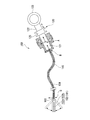
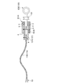
- FIG. 2 is a schematic diagram of a surgical instrument used together with the surgery support apparatus.
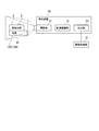
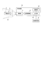
- FIG. 3 is a block diagram of a detection device in the surgery support apparatus.
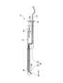
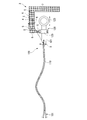
- FIG. 4 is a schematic diagram showing a part of the slave manipulator in the surgery support apparatus.
- FIG. 5 is a block diagram of a control device and a slave arm in the surgery support apparatus.
- the surgery support apparatus 1 includes a master manipulator 2 (operation input unit), a slave manipulator 20 (operation unit), a display device 29, and a control device 30. Further, the surgery support apparatus 1 is configured so that a known soft treatment instrument can be attached as the surgical instrument 100.
- the configuration of the surgical instrument 100 is not particularly limited.
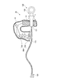
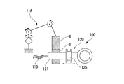
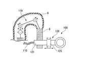
- the surgical instrument 100 used by being attached to the surgery support apparatus 1 includes a treatment unit 101, an insertion unit 110, and an operation unit 120 as illustrated in FIG. Prepare.
- the treatment unit 101 can appropriately adopt a known configuration that performs treatment on a living tissue, such as forceps, a needle, and a high-frequency knife.
- the treatment unit 101 operates by an operation on the operation unit 120.
- the operation of the treatment unit 101 includes, for example, opening and closing of a forceps, projecting and retracting of a needle from the insertion unit 110, and application of a high-frequency current to a high-frequency knife.
- the treatment part 101 is demonstrated using the example provided with the forceps 102 which can be opened and closed.
- the forceps 102 has a pair of forceps pieces 102 a and 102 b that are rotatably connected to each other by pins 103. Further, a wire 104 for rotating the forceps pieces 102 a and 102 b around the central axis of the pin 103 is connected to the forceps pieces 102 a and 102 b. One end of the wire 104 is connected to the forceps 102, the wire 104 is inserted into the insertion unit 110, and the other end is connected to the operation unit 120.
- the insertion part 110 is a soft cylindrical member.
- the configuration of the insertion portion 110 is not particularly limited as long as it is cylindrical.
- the insertion portion 110 includes a coil sheath in which a metal wire is wound in a coil shape, and a covering member that covers the coil sheath. ing.
- the wire 104 connected to the forceps pieces 102 a and 102 b is inserted into the insertion portion 110.
- the operation unit 120 is fixed to the insertion unit 110.
- the operation unit 120 includes a rod-shaped operation main body 121 with the insertion unit 110 fixed to the tip, and a slider 125 connected to the operation main body 121 and fixed to the wire 104.
- the operation main body 121 has a rail portion 122 that holds the slider 125 movably forward and backward.
- the operation main body 121 is provided with a finger hooking portion 123 for hooking a user's finger on the end opposite to the end on which the insertion portion 110 is fixed.
- the slider 125 is a substantially columnar member in which a recess that can be hung by a user's finger is formed on the outer peripheral surface. By moving the slider 125 forward and backward with respect to the operation main body 121, the wire 104 moves forward and backward within the insertion portion 110.
- the surgical instrument 100 is configured such that at least the treatment section 101 can be sterilized. Further, the entire surgical instrument 100 may have a sterilizable configuration.
- the master manipulator 2 shown in FIG. 1 is provided for operating the slave manipulator 20 in accordance with the movement of the user.
- the master manipulator 2 includes a detected body 3 attached to the surgical instrument 100 and a detection device 10 that detects the detected body 3.
- the surgery support apparatus 1 includes an operation input unit that issues an operation command for operating the slave manipulator 20.
- the master manipulator 2 and the conversion processing unit 31 in the control device 30 constitute an operation input unit.
- the body 3 to be detected is attached at a position that does not get in the way when the user holds the operation unit 120 of the surgical instrument 100.
- the detection target 3 is detachably fixed in the vicinity of the connection portion between the operation main body 121 and the insertion portion 110.
- the detected body 3 includes a main body 4 attached to the operation unit 120 and a marker 5 provided on the main body 4. Further, the entire detection object 3 is configured to be sterilizable.
- the material to be detected 3 is appropriately made of materials so that it can be sterilized by any method such as high-pressure steam sterilization, ethylene oxide gas sterilization, chemical sterilization such as alcohol or formalin, ultraviolet sterilization, or other sterilization methods. Selected.
- the shape of the detection target 3 is not particularly limited.
- the body 3 to be detected can have a rectangular parallelepiped shape or a spherical shape.
- a clean doctor or the like can touch the detected body 3. Accordingly, a clean doctor or the like operates the body to be detected 3, and a doctor or the like who operates the body to be detected 3 can work in the clean field as it is. As a result, treatment such as surgery can be performed more reliably and efficiently.
- the main body 4 is a member provided with a marker 5 on the outer surface.
- the markers 5 provided on the main body portion 4 are provided at three or more locations that are separated from each other on the outer surface of the main body portion 4.
- Each marker 5 has a predetermined color and shape.
- the main body 4 is provided with a plurality of markers 5 having the same shape, the same size, and the same color.
- Each marker 5 is formed on the outer surface of the main body 4 by printing or the like, for example.
- the marker 5 is disposed with its position relative to the main body 4 positioned. For this reason, the position and orientation of the marker 5 correspond to the position and orientation of the main body 4. Further, since the main body unit 4 is fixed to the operation main body 121 of the operation unit 120, the position and posture of the marker 5 correspond to the position and posture of the operation unit 120. Further, when three markers 5 are provided on the main body 4, the three markers 5 are arranged so that the lengths of the three sides of the triangle having each marker 5 as a vertex are different from each other. Thereby, the attitude
- FIG. Each marker 5 is provided on a flat portion or a curved portion on the outer surface of the main body 4.
- the marker 5 may be provided in the main-body part 4 so that it may respond when the marker 5 is shielded with respect to the detection apparatus 10 by the obstruction etc. during operation. When a certain marker 5 is shielded, the position / orientation is obtained by using an extra marker 5 instead. Note that three or more markers 5 may be arranged on one sheet and the sheet may be attached to the outer surface of the main body 4.
- the detection device 10 includes a photographing unit 11, an image recognition unit 12, and an output unit 13.
- the imaging unit 11 is an apparatus that images the detected body 3 when the surgical instrument 100 to which the detected body 3 is attached is being used by a user.
- the imaging field of view of the imaging unit 11 can capture the entire space (hereinafter referred to as “work space Q1”) in which the detected object 3 is moved by the user when the surgery support apparatus 1 is used.
- the photographing unit 11 includes at least a first camera that photographs from a predetermined direction with respect to the work space Q1, and a second camera that photographs from a direction different from the predetermined one direction. Yes.
- photography part 11 can image
- the photographing unit 11 may have three or more cameras.
- the imaging unit 11 may have a redundant configuration including a spare camera assuming that the user himself / herself or another obstacle enters between the detected object 3 and the camera.
- the imaging unit 11 outputs the captured image to the image recognition unit 12.
- the image recognition unit 12 recognizes the marker 5 from the photographed image by image recognition processing. Furthermore, the image recognition unit 12 calculates the position and orientation of the marker 5 as coordinate information from the positional relationship of each marker 5 in the work space Q1, and outputs the coordinate information to the output unit 13.
- the coordinate information calculated in the image recognition unit 12 is coordinate information (hereinafter referred to as “first coordinate information A”, see FIG. 2) using a coordinate system unique to the detected object 3.
- the output unit 13 outputs the first coordinate information A calculated by the image recognition unit 12 to the conversion processing unit 31 of the control device 30.
- the first coordinate information A output from the output unit 13 is information for the conversion processing unit 31 to specify the position and orientation of the detection target 3.
- the first coordinate information A is output from the output unit 13 according to a predetermined transmission timing regardless of whether or not the detected object 3 is moving in the work space Q1.
- the slave manipulator 20 includes a slave arm 21 to which an endoscope apparatus and the surgical instrument 100 (hereinafter may be collectively referred to as “the surgical instrument 100 or the like”) are attached. And an actuator (not shown) for operating the surgical instrument 100 and the slave arm 21.
- Each actuator provided in the slave manipulator 20 operates according to a drive signal output from the control device 30.
- the endoscopic device provided in the slave manipulator 20 acquires images of the treatment object and the surgical instrument 100 and outputs them to the display device 29.
- the slave arm 21 has an attachment portion 22 for attaching the surgical instrument 100.
- the attachment portion 22 includes a hollow portion 23 into which the insertion portion 110 is inserted, and a treatment portion moving mechanism 24 for changing the orientation of the treatment portion 101.
- the hollow portion 23 is opened at the proximal end portion and the distal end portion of the slave arm 21.
- a fixing portion 28 for fixing the insertion portion 110 is provided in the opening 23 a of the hollow portion 23 arranged at the proximal end portion of the slave arm 21. Further, the treatment portion 101 of the surgical instrument 100 protrudes from the opening 23b formed at the distal end portion of the slave arm 21.
- the treatment portion moving mechanism 24 includes a holding portion 25 that holds the distal end portion of the insertion portion 110 of the surgical instrument 100, and an actuator 26 that causes the holding portion 25 to bend.
- the holding part 25 is provided at the distal end of the slave arm 21. Moreover, the holding
- the treatment section 101 can be prevented from rotating unnecessarily around the central axis of the insertion section 110.
- a wall portion, a cylindrical portion, or the like that supports the outer surface of the insertion portion 110 may be formed in the holding portion 25 instead of a clip that engages with the outer surface of the insertion portion 110. In this case, the treatment unit 101 can be moved back and forth or rotated with respect to the holding unit 25 as necessary.
- any part of the insertion part 110 may be attached to the holding part 25, but in this embodiment, the outer part of the insertion part 110 that is slightly proximal to the treatment part 101 is attached to the holding part 25. It is configured. In the present embodiment, the holding part 25 is configured to bend slightly on the proximal side of the treatment part 101 in a state where the surgical instrument 100 is attached to the holding part 25. Moreover, the structure to which the insertion part 110 is attached may be sufficient as the holding
- the actuator 26 is disposed inside the slave arm 21 and connected to the holding unit 25 via the connecting rod 27.
- the slave arm 21 is provided with position and orientation detection means 38 (see FIG. 5) for detecting the position and orientation of the slave arm 21 and the position and orientation of the treatment section moving mechanism 24.
- the position / orientation detection means 38 is, for example, an encoder or the like provided on each joint axis of the slave arm 21 itself or the treatment section moving mechanism 24. From these joint displacement amounts, the position and posture of the slave arm 21 and the position and posture of the treatment unit 101 held by the holding unit 25 can be calculated by solving kinematics.
- the display device 29 is attached to the same base as the detection device 10 of the master manipulator 2 and is installed in front of the user.
- the display device 29 has a display panel that displays an image acquired by the endoscope device.
- a liquid crystal panel, an organic EL panel, or the like can be appropriately selected and employed.
- the display panel may be a panel that displays a stereoscopically visible image.
- a panel that displays an image that can be viewed stereoscopically can employ a configuration in which images for the right eye and the left eye can be separated by dedicated glasses, a configuration that enables autostereoscopic viewing, and the like.
- the control device 30 includes a conversion processing unit 31, a slave control unit 34, and a storage unit 37.
- the conversion processing unit 31 is connected to the detection device 10.
- the slave control unit 34 is connected to the conversion processing unit 31 and is connected to each actuator 26 of the slave manipulator 20.
- the storage unit 37 is connected to the conversion processing unit 31 and the slave control unit 34.
- the conversion processing unit 31 includes an information acquisition unit 32 and an operation command generation unit 33 connected to the information acquisition unit 32.
- the information acquisition unit 32 receives the first coordinate information A output from the detection device 10 illustrated in FIG.
- the information acquisition unit 32 acquires first coordinate information A calculated using a coordinate system unique to the detection target 3 (see FIG. 1), and sends the first coordinate information A to the operation command generation unit 33. Output.
- the first coordinate information A of the detection target 3 output from the detection device 10 shown in FIG. 3 is input to the operation command generation unit 33 via the information acquisition unit 32.
- the first coordinate information A of the detected body 3 is input to the operation command generation unit 33 as tracking information of the detected body 3 according to the predetermined transmission timing.
- the operation command generation unit 33 has a coordinate system conversion function for converting the coordinate system of the tracking information of the detection target 3 into the coordinate system of the operation unit 120 to which the detection target 3 is attached.
- the coordinate system of the operation unit 120 is a coordinate system determined by the position of the marker 5 on the detection target 3 and the shape of the operation unit 120.
- the coordinate system of the operation unit 120 is a three-dimensional coordinate system in which the connection position between the operation main body 121 and the insertion unit 110 is the origin.
- Information for specifying the coordinate system of the operation unit 120 is stored in the storage unit 37 as surgical tool information, and is appropriately referred to by the operation command generation unit 33.
- the first coordinate information A in the tracking information of the detection target 3 is coordinate information (hereinafter referred to as “second coordinate information”) in accordance with a three-dimensional coordinate system having the connection position between the operation main body 121 and the insertion unit 110 as an origin. B ”(see FIG. 2).
- the transformation of the coordinate system can be performed using a transformation matrix as shown in Equation 1 below.
- ⁇ Pm ⁇ is the coordinates of the detected object 3 based on the coordinate system unique to the detected object 3
- ⁇ T ⁇ is a known transformation matrix based on the surgical instrument information
- ⁇ Ps ⁇ is This is the coordinates of the operation unit 120 with the connection position between the operation body 121 and the insertion unit 110 as the origin.
- the operation command generation unit 33 outputs an operation command for operating the slave manipulator 20 and the surgical instrument 100 shown in FIG.
- the operation command issued by the operation command generation unit 33 includes, for example, second coordinate information B indicating the position and posture after the movement of the slave arm 21 and the surgical instrument 100 to be operated.
- the slave control unit 34 includes an inverse kinematics calculation unit 35 connected to the conversion processing unit 31 and a drive amount generation unit 36 connected to the inverse kinematics calculation unit 35.
- the inverse kinematics calculation unit 35 acquires tracking information of the slave manipulator 20 from the position / orientation detection means 38 provided in the slave manipulator 20.
- the tracking information of the slave manipulator 20 is the coordinate information indicating the position and posture of the surgical instrument 100 and the slave arm 21 and the position and posture of the treatment unit 101 provided on the surgical instrument 100 (hereinafter referred to as “third coordinate information C”). .)
- the coordinate system in the tracking information of the slave manipulator 20 is a three-dimensional coordinate system having a position slightly distal to the holding unit 25 as an origin. In the state where the surgical instrument 100 is attached to the holding unit 25, the boundary portion between the treatment unit 101 and the insertion unit 110 is the origin of the coordinate system in the tracking information of the slave manipulator 20.
- the opening / closing angles of the forceps pieces 102a and 102b (see FIG. 2) in the treatment unit 101 may not be included in the tracking information of the slave manipulator 20. This is because since the forceps pieces 102a and 102b are directly connected to the slider 125 of the operation unit 120 by the wire 104, the operational feeling of the forceps pieces 102a and 102b is directly transmitted to the user.
- the inverse kinematics calculation unit 35 receives the operation command output from the conversion processing unit 31 in response to the operation command from the operation command generation unit 33, and the movement angle information of each joint and the surgical instrument 100 in the slave manipulator 20. And output to the drive amount generator 36.
- the inverse kinematics calculation unit 35 may have a coordinate conversion function for matching the coordinate system of the second coordinate information B and the coordinate system of the third coordinate information C by coordinate conversion as necessary.
- the coordinate system of the second coordinate information B and the coordinate system of the third coordinate information C are matched by coordinate transformation, the user who moves the treatment unit 101 while viewing the endoscope image intuitively moves the treatment unit 101 Can be made.
- the inverse kinematics calculator 35 may have a scale conversion function for matching the scale in the tracking information of the detection target 3 and the scale in the tracking information of the slave manipulator 20. By the coordinate conversion function and the scale conversion function, the operation of the user who moves the detected object 3 while looking at the display device 29 can be appropriately reflected in the operations of the slave manipulator 20 and the surgical instrument 100.
- the drive amount generator 36 outputs a drive signal that defines the drive amount of each actuator 26 corresponding to the movement angle information output from the inverse kinematics calculator 35 to each actuator 26 of the slave manipulator 20.
- FIG. 6 and 7 are schematic views showing the operation at the time of using the surgery support apparatus.
- the user inserts the insertion part 110 of the surgical instrument 100 into the hollow part 23 of the slave arm 21 as shown in FIG. 6.
- the outer surface of the insertion portion 110 is attached to the holding portion 25 at a position where the treatment portion 101 protrudes from the opening 23 b of the hollow portion 23 located on the distal end side of the slave arm 21.
- the work of attaching the insertion unit 110 to the holding unit 25 may be performed manually by a clean person or remotely.
- the surgical instrument 100 may be fixed using both the clip of the holding unit 25 and the fixing unit 28 of the slave arm 21. Further, the surgical instrument 100 may be fixed only by any one of the clip of the holding part 25 and the fixing part 28 of the slave arm 21.
- the user holds the operation unit 120 of the surgical instrument 100 and moves the operation unit 120 as necessary as shown in FIG. Then, the to-be-detected body 3 attached to the operation part 120 also moves together with the operation part 120, and the marker 5 provided on the to-be-detected body 3 moves in the work space Q1. At this time, the marker 5 is imaged by the imaging unit 11 provided in the detection apparatus 10 shown in FIG.
- the detection device 10 detects the position and orientation of the marker 5 in the work space Q1, and outputs the first coordinate information A to the conversion processing unit 31 of the control device 30.
- the operation command generation unit 33 converts the first coordinate information A based on the first coordinate information A (tracking information of the detection target 3) to generate the second coordinate information B. In the conversion processing unit 31, an operation command (see FIG. 1) including the second coordinate information B is generated. The operation command generated by the operation command generation unit 33 is output to the inverse kinematics calculation unit 35 of the slave control unit 34.
- the inverse kinematics calculation unit 35 compares the second coordinate information B included in the operation command with the tracking information (third coordinate information C) of the slave manipulator 20 acquired from the slave manipulator 20. Using the comparison result, the inverse kinematics calculation unit 35 moves the joint angles for controlling the position and posture of the slave arm 21 and moves the joints for controlling the position and posture of the treatment unit 101. The angle is calculated and output to the drive amount generator 36 as movement angle information.
- the drive amount generation unit 36 generates a drive signal that defines the drive amount of each of the actuators 26 that move the slave arm 21 and the surgical instrument 100 according to the movement angle information output from the inverse kinematics calculation unit 35. And the surgical instrument 100 is moved.
- the operation of changing the direction of the portion protruding from the distal end of the slave arm 21 in the surgical instrument 100 is performed by the bending operation of the holding portion 25.
- the position of the holding unit 25 can be moved, and thereby the position and posture of the surgical instrument 100 can be changed.
- the slave arm 21 itself May be moved, and only the holding portion 25 may be bent.
- the position and orientation of the treatment unit 101 are controlled based on the second coordinate information B.
- the operator can obtain an operational feeling that the treatment unit 101 is fixed at the connection position between the operation main body 121 and the insertion unit 110. That is, in this embodiment, the user who operates the operation unit 120 uses the surgical instrument 100 with an operational feeling as if using a rigid instrument in which the forceps pieces 102 a and 102 b are attached to the distal end of the operation main body 121. Can be used.
- the forceps pieces 102 a and 102 b are connected to the wire 104.
- the wire 104 to which the forceps pieces 102 a and 102 b are connected extends through the insertion portion 110 to the operation portion 120. Further, in the operation unit 120, the wire 104 is connected to the slider 125. For this reason, by sliding the slider 125 with respect to the operation main body 121, the forceps pieces 102a and 102b are opened and closed. A feeling when a tissue or the like is grasped by the pair of forceps pieces 102a and 102b is transmitted to the slider 125 through the wire 104, and is transmitted as an operational feeling to a user who operates the slider 125.
- the surgical instrument 100 When using the surgery support apparatus 1 shown in FIG. 1, the surgical instrument 100 may be removed from the slave arm 21.
- the surgical instrument 100 when a biopsy forceps is used as the surgical instrument 100, when the biopsy sample is taken out of the body, only the surgical instrument 100 can be pulled out of the body without removing the slave arm 21 from the patient. Good sex.
- the clip of the holding unit 25 (see FIG. 4) is moved by remote operation to release the fixed state between the holding unit 25 and the insertion unit 110, and the fixing unit 28 of the slave arm 21 and the surgical instrument 100 are further released.
- the fixing to the insertion portion 110 is released manually, for example.
- the insertion part 110 of the surgical instrument 100 is soft, the insertion field can be removed from the hollow part 23 even if the slave arm 21 and the holding part 25 are bent by simply pulling out the insertion part 110 from the hollow part 23 of the slave arm 21. Moreover, the insertion part 110 can also be inserted in the hollow part 23 again as needed. In this case, the treatment portion 101 located at the distal end of the insertion portion 110 is guided to the same position as before the surgical instrument 100 is pulled out. Thereafter, the clip of the holding unit 25 is moved by remote operation to fix the insertion unit 110 to the holding unit 25, and the operation can be continued.
- the detected body 3 is provided in the operation unit 120 of the surgical instrument 100, and the position and orientation of the detected body 3 are specified by the detection apparatus 10.
- the position and posture of the surgical instrument 100 are controlled. Therefore, control of the position and posture of the slave manipulator 20, control of the position and posture of the surgical instrument 100, and operation of the treatment unit 101 provided on the surgical instrument 100 can be easily performed by one user.
- the flexible insertion portion 110 is fixed to the fixing portion 28 of the slave arm 21.
- the treatment unit 101 is moved by moving the slave arm 21 and the holding unit 25 instead of the force directly transmitted from the operation unit 120 so as to move the insertion unit 110 back and forth or rotate. Move.
- the problem that the operation amount of the operation unit 120 does not correspond to the movement amount of the treatment unit 101 due to the influence of friction resistance between the hollow portion 23 of the slave arm 21 and the insertion portion 110 of the surgical instrument 100 does not occur.
- the position and posture of the treatment unit 101 can be changed smoothly.
- Modification 1 Next, a modification of this embodiment will be described. 8 to 12 are schematic views showing the configuration of this modification.
- the coordinate system of the detected object 3 is defined in advance so that the origin of the coordinate system unique to the detected object 3 becomes the origin of the coordinate system unique to the operation unit 120.
- the detection object 3 has a predetermined shape of the operation unit 120 corresponding to the detection object 3 in advance.
- the position of the marker 5 is constant with respect to the connection position between the operation main body 121 and the insertion unit 110.
- the connection position between the operation main body 121 and the insertion portion 110 can be set as the origin of the second coordinate information B regardless of the shape of the detected body 3.
- the detection target 3 corresponding to the operation unit 120 is provided, and the detection target 3A corresponding to another operation unit 120A is provided.
- the detected object 3 or the operation unit 120 may be provided with means for causing the detection device 10 to identify the shape feature of the operation unit 120.
- the detection target 3 is provided with a labeling unit 6 for causing the detection device 10 to identify a corresponding operation unit 120 having a specific shape.
- the detection device 10 is provided with an identification unit 14 that recognizes the marker unit 6 and identifies the surgical instrument 100.
- the operation main body 121B includes a detected body 3B corresponding to the operation unit 120B.
- the operation main body 121C includes a detected body 3C corresponding to another operation unit 120C.
- the marker 6B provided on the detection object 3B holds surgical tool information defined based on the shape of the operation unit 120B or information for specifying the surgical tool information.
- the labeling part 6C provided in the detection object 3C holds surgical tool information defined based on the shape of the operation part 120C or information for specifying the surgical tool information.
- the marking units 6B and 6C are, for example, a pattern having a specific shape provided separately from the marker 5, a wireless tag provided separately from the marker 5, or a type indicating the type of the operation unit 120 by a combination of the arrangement of the markers 5. It can be appropriately selected and employed.
- the identification unit 14 of the detection apparatus 10 stores information for defining the position of the origin of the second coordinate information B in the plurality of surgical tools 100 corresponding to the marker unit 6.
- the marker 5 is detected by the detection device 10 and the marker unit 6 is recognized by the detection device 10.
- the sign part 6 is photographed by the photographing part 11 in the work space Q1, and the origin of the second coordinate information B corresponding to the pattern of the sign part 6 is set. Is done.
- the origin of the second coordinate information B is reset corresponding to the other marker 6. Is done.
- the operation support apparatus can reduce the calculation for converting the coordinate system while using a certain operation unit 120 by having such a configuration.
- the surgical instrument 100 is exchanged during surgery or the like, since the origin corresponding to the operation unit 120 of each treatment unit 101 is automatically set, operability is good.
- the surgical instrument information in the storage unit 37 may be set based on the information held in the sign unit 6.
- the position of the origin of the second coordinate information B may be set to a position other than the connection position between the operation main body 121 and the insertion unit 110. Further, based on the technique disclosed in this modification, the origin can be set for the operation unit 120 that does not have a configuration corresponding to the operation main body 121 or the insertion unit 110.
- FIG. 13 is a schematic diagram showing this modification.
- the detection object 3 includes a grip portion 7 that is attached to the slider 125 of the operation portion 120 and is gripped by the operator.
- the marker 5 is provided in the to-be-detected body 3 similarly to the said 1st Embodiment.
- the user grips the grip portion 7 of the detection target 3 and puts a finger on the finger hook portion 123 of the operation main body 121 to operate the operation portion 120.
- the second coordinate information B described in the first embodiment is based on the operation main body 121 and the insertion portion 110 at a position where the operation main body 121 is completely pulled toward the gripping portion 7 with respect to the slider 125, for example. Is coordinate information according to a three-dimensional coordinate system with the connection position as the origin. For this reason, in this modification, the operation main body 121 moves forward and backward with respect to the origin in the second coordinate information B. Even with such a configuration, the same effects as those of the first embodiment described above can be obtained.
- the user operates the treatment unit 101 by holding the holding unit 7 of the detected body 3 and placing the finger on the operation main body 121 to move the operation main body 121.
- the gripping unit 7 generally does not move, and a relative movement that causes the operation main body 121 to move forward and backward with respect to the gripping unit 7 generally occurs.
- the origin whose positional relationship is fixed with respect to the grip portion 7 is the origin in the second coordinate information B.
- the origin in 2nd coordinate information B is linked
- the to-be-detected part attached to the operation main body 121 may be further provided similarly to the above-mentioned 1st Embodiment.
- FIG. 14 is a schematic diagram showing a part of the surgery support apparatus of the present embodiment.
- FIG. 15 is a schematic diagram showing another configuration example in the present embodiment.
- FIG. 16 is a schematic diagram showing still another configuration example in the present embodiment.
- the surgery support apparatus 1 ⁇ / b> A includes an adapter 8 that is attached to the operation unit 120 instead of the detected object 3 having the marker 5 described in the first embodiment. .
- the adapter 8 and the operation unit 120 are connected via an intermediate member 9 that can be sterilized.
- the intermediate member 9 is a drape formed in a bag shape. Thereby, the operation part 120 is maintained clean.
- the surgery support apparatus 1A is a detection apparatus 10A including an articulated arm 11A connected to the adapter 8 and a position and orientation detection unit 12A instead of the detection apparatus 10 including the imaging unit 11 and the image recognition unit 12. Is provided.
- the position / orientation detection unit 12A detects the position and orientation of the articulated arm 11A.
- the articulated arm 11 ⁇ / b> A is covered by the drape interposed between the adapter 8 and the operation unit 120 as the intermediate member 9 when used.
- the position / orientation detection unit 12A includes an angle detector such as an encoder that detects the movement angle of each joint of the multi-joint arm 11A, and determines the coordinates of the detection target 3 based on the angle information output from each angle detector. get.
- the detection apparatus 10 ⁇ / b> A has the same output unit 13 as that in the first embodiment, and can output tracking information of the detected object 3 to the conversion processing unit 31 through the output unit 13.
- the position and posture of the detected body 3 are specified using the multi-joint arm 11A.
- the intermediate member 9 may not be a drape.
- an annular member interposed between the adapter 8 and the operation unit 120 may be employed as the intermediate member 9.
- the adapter 8 instead of covering the adapter 8 with the drape as the intermediate member 9, the adapter 8 can be sterilized, and the sterilized drape (intermediate member 9) is replaced with the adapter 8. It may be fixed to.
- the concrete structure is not restricted to this embodiment, The design change etc. of the range which does not deviate from the summary of this invention are included.
- the treatment portion moving mechanism 24 may have a mechanism that rotates the treatment portion 101 around the axis of the insertion portion 110.
- the constituent elements shown in the above-described embodiments and modifications can be combined as appropriate.
- the design change etc. with respect to the said specific structure are not limited to the said matter.
- a surgery support device that can be operated intuitively and easily by an operator can be provided.
Landscapes
- Health & Medical Sciences (AREA)
- Surgery (AREA)
- Engineering & Computer Science (AREA)
- Life Sciences & Earth Sciences (AREA)
- Medical Informatics (AREA)
- Robotics (AREA)
- Biomedical Technology (AREA)
- Heart & Thoracic Surgery (AREA)
- Nuclear Medicine, Radiotherapy & Molecular Imaging (AREA)
- Molecular Biology (AREA)
- Animal Behavior & Ethology (AREA)
- General Health & Medical Sciences (AREA)
- Public Health (AREA)
- Veterinary Medicine (AREA)
- Manipulator (AREA)
- Surgical Instruments (AREA)
- Endoscopes (AREA)
Abstract
この手術支援装置は、操作入力部と、術具が取り付けられ、術具を動作させる動作部と、を備えた手術支援装置であって、術具は、処置部と、軟性挿入部と、軟性挿入部に固定された操作部と、を有する。操作入力部は、操作部に取り付けられる被検出体と、被検出体を検出する検出装置と、を備える。検出装置は、被検出体の位置および姿勢のうちの少なくともいずれかを特定可能な情報を算出し、制御装置は、検出装置により算出された情報に基づいて、術具を移動させるための指令を操作指令として動作部へ出力することにより術具の動作を制御する。
Description
本発明は、遠隔操作により操作される手術支援装置に関する。本願は、2012年5月18日に、日本に出願された特願2012-114484号に基づき優先権を主張し、その内容をここに援用する。
従来、手術に使用される医療器具として、処置具が挿入される処置具チャンネルを備えた電動内視鏡が知られている(例えば特許文献1参照)。
特許文献1に記載の医療器具は、ジョイスティックを使用して電動内視鏡の湾曲部を湾曲させ、また、処置具チャンネルに種々の処置具を挿入することにより、手術をすることができるように構成されている。
特許文献1に記載の医療器具は、ジョイスティックを使用して電動内視鏡の湾曲部を湾曲させ、また、処置具チャンネルに種々の処置具を挿入することにより、手術をすることができるように構成されている。
しかし、特許文献1に記載の医療器具においては、電動内視鏡の湾曲部の操作と処置具の操作が独立しているため、片手でジョイスティックの操作をしながら処置具を動作させることは難しい。また、電動内視鏡の湾曲部の位置及び姿勢と、処置具の位置及び姿勢との対応関係が分かりにくく、直感的な操作が困難である。
本発明は、上述した事情に鑑みてなされたものであって、その目的は、操作者が直感的かつ容易に操作できる手術支援装置を提供することである。
本発明の第一の態様に係る手術支援装置は、使用者からの入力に基づいて操作指令を発する操作入力部と、術具が取り付けられ前記操作指令に基づいて前記術具を動作させる動作部と、を備えた手術支援装置であって、前記術具は、処置対象物に対して処置を行う処置部と、前記処置部が一端に設けられた長尺の軟性挿入部と、前記軟性挿入部に固定され前記処置部に連結された操作部と、を有する。前記操作入力部は、前記術具の前記操作部に取り付けられる被検出体と、前記被検出体を検出する検出装置と、を備える。前記検出装置は、前記被検出体の位置および姿勢のうちの少なくともいずれかを特定可能な情報を算出する。前記操作入力部は、前記検出装置により算出された情報に基づいて、前記術具を移動させるための指令を前記操作指令として前記動作部へ出力することにより前記術具の動作を制御する。
本発明の第二の態様によれば、第一の態様に係る手術支援装置において、前記被検出体は、前記操作部に取り付けられる本体部と、前記本体部に設けられたマーカと、を有してもよい。また、前記検出装置は、前記マーカを用いて前記情報を算出してもよい。
本発明の第三の態様によれば、第一または第二の態様に係る手術支援装置において、前記検出装置は、前記操作部に対して所定の位置関係を有するように設定された原点を基準とする座標系を用いて前記情報を算出してもよい。
本発明の第四の態様によれば、第一から第三のいずれかの態様に係る手術支援装置において、前記被検出体は、前記術具を前記検出装置に識別させる標識部を有してもよい。また、前記検出装置は、前記標識部を認識して前記術具と他の術具とを識別し、前記情報を算出するための座標系の原点を前記標識部に応じて設定してもよい。
本発明の第五の態様によれば、第一から第四のいずれかの態様に係る手術支援装置において、前記動作部は、前記操作指令に基づいて位置および姿勢のうちの少なくともいずれかが制御されるスレーブアームを有してもよい。前記スレーブアームは、前記軟性挿入部が挿入され前記スレーブアームの遠位端部に開口された中空部を有してもよい。また、前記処置部は、前記中空部の遠位端部に設けられた開口から突没してもよい。
本発明の第六の態様によれば、第一から第五のいずれかの態様に係る手術支援装置において、前記動作部は、前記操作指令に基づいて位置および姿勢のうちの少なくともいずれかが制御されるスレーブアームと、前記スレーブアームに設けられ前記術具が取り付けられる取付部と、前記取付部に設けられ前記操作指令に基づいて位置および姿勢のうちの少なくともいずれかが制御され前記処置部を移動させる処置部移動機構とを有していてもよい。
本発明の第七の態様によれば、第一、第五、第六のいずれかの態様に係る手術支援装置において、前記被検出体は、前記操作部に取り付けられるアダプタを有してもよい。前記検出装置は、前記アダプタに連結された多関節アームと、前記多関節アームの位置及び姿勢を検知して前記情報として出力する位置姿勢検知部と、を有していてもよい。
本発明の第八の態様によれば、第一から第七のいずれかの態様に係る手術支援装置において、前記被検出体は滅菌可能であってもよい。
本発明の第九の態様によれば、第一から第七のいずれかの態様に係る手術支援装置において、前記被検出体は滅菌可能な部材を介して前記操作部に取り付けられてもよい。
本発明の手術支援装置によれば、操作者が直感的かつ容易に手術支援装置を操作できる。
(第1実施形態)
本発明の第1実施形態の手術支援装置について説明する。図1は、本実施形態の手術支援装置を示す全体図である。図2は、手術支援装置とともに使用される術具の模式図である。図3は、手術支援装置における検出装置のブロック図である。図4は、手術支援装置におけるスレーブマニピュレータの一部を示す模式図である。図5は、手術支援装置における制御装置及びスレーブアームのブロック図である。
本発明の第1実施形態の手術支援装置について説明する。図1は、本実施形態の手術支援装置を示す全体図である。図2は、手術支援装置とともに使用される術具の模式図である。図3は、手術支援装置における検出装置のブロック図である。図4は、手術支援装置におけるスレーブマニピュレータの一部を示す模式図である。図5は、手術支援装置における制御装置及びスレーブアームのブロック図である。
図1に示すように、手術支援装置1は、マスタマニピュレータ2(操作入力部)、スレーブマニピュレータ20(動作部)、表示装置29、及び制御装置30を備える。また、手術支援装置1は、公知の軟性処置具を術具100として取り付けることができるように構成されている。
術具100の構成は特に限定されないが、例えば、手術支援装置1に取り付けて使用される術具100は、図2に示すように、処置部101と、挿入部110と、操作部120とを備える。
処置部101は、鉗子、針、高周波ナイフなど、生体組織に対して処置を行う公知の構成を適宜選択して採用することができる。本実施形態では、処置部101は、操作部120における操作によって動作する。処置部101の動作は、例えば鉗子が開閉したり、針が挿入部110から突没したり、高周波ナイフに高周波電流が通電されたりする等が挙げられる。以下では、処置部101として、開閉可能な鉗子102が設けられている例を用いて説明する。
処置部101は、鉗子、針、高周波ナイフなど、生体組織に対して処置を行う公知の構成を適宜選択して採用することができる。本実施形態では、処置部101は、操作部120における操作によって動作する。処置部101の動作は、例えば鉗子が開閉したり、針が挿入部110から突没したり、高周波ナイフに高周波電流が通電されたりする等が挙げられる。以下では、処置部101として、開閉可能な鉗子102が設けられている例を用いて説明する。
鉗子102は、ピン103により互いに回動自在に連結された一対の鉗子片102a、102bを有する。さらに、各鉗子片102a、102bには、各鉗子片102a、102bをピン103の中心軸線回りに回動させるためのワイヤ104が連結されている。ワイヤ104は、一端が鉗子102に連結されており、挿入部110内に挿通され、他端が操作部120に連結されている。
挿入部110は、軟性の筒状部材である。本実施形態では、挿入部110の構成は筒状であれば特に限定されないが、たとえば、挿入部110は、金属線がコイル状に巻かれたコイルシースと、コイルシースを被覆する被覆部材とを有している。鉗子片102a、102bに連結された上述のワイヤ104は、挿入部110内に挿通されている。
操作部120は、挿入部110に固定されている。具体的には、操作部120は、挿入部110が先端に固定された棒状の操作本体121と、操作本体121に連結されワイヤ104に固定されたスライダ125とを備える。
操作本体121は、スライダ125を進退自在に保持するレール部122を有する。操作本体121は、挿入部110が固定された側の端とは反対側の端に、使用者の指を掛ける指掛け部123が設けられている。
スライダ125は、使用者の指を掛けることができる窪みが外周面に形成された略円柱状の部材である。操作本体121に対してスライダ125を進退移動させることにより、挿入部110内でワイヤ104が進退する。
術具100は、少なくとも処置部101が滅菌可能に構成されている。また、術具100の全体が滅菌可能な構成を有してもよい。
図1に示すマスタマニピュレータ2は、使用者の動きに応じてスレーブマニピュレータ20を動作させるために設けられている。マスタマニピュレータ2は、術具100に取り付けられる被検出体3と、被検出体3を検出する検出装置10とを備える。また、手術支援装置1は、スレーブマニピュレータ20を動作させるための操作指令を発する操作入力部を有する。本実施形態では、マスタマニピュレータ2と、制御装置30における変換処理部31とによって、操作入力部が構成されている。
被検出体3は、使用者が術具100の操作部120を把持した際に邪魔にならない位置に取り付けられる。例えば、本実施形態では、被検出体3は、操作本体121と挿入部110との接続部分の近傍に着脱可能に固定される。被検出体3は、操作部120に取り付けられる本体部4と、本体部4に設けられたマーカ5とを有する。また、被検出体3は、全体が滅菌可能に構成されている。被検出体3は、たとえば、高圧蒸気滅菌、エチレンオキサイドガス滅菌、アルコールやホルマリン等の薬液による滅菌、紫外線滅菌等の何れかの方法またはその他の滅菌方法により滅菌可能となるように、材料が適宜選択される。
被検出体3の形状は特に限定されない。例えば、被検出体3は、直方体状や球状等の形状とすることができる。被検出体3を滅菌可能に構成することで、清潔状態の医師等が被検出体3に触れることが可能となる。これにより、清潔状態の医師等が被検出体3を操作し、被検出体3を操作する医師等がそのまま清潔野で作業することができる。その結果、手術等の処置がより確実かつ効率的に実施できる。
被検出体3の形状は特に限定されない。例えば、被検出体3は、直方体状や球状等の形状とすることができる。被検出体3を滅菌可能に構成することで、清潔状態の医師等が被検出体3に触れることが可能となる。これにより、清潔状態の医師等が被検出体3を操作し、被検出体3を操作する医師等がそのまま清潔野で作業することができる。その結果、手術等の処置がより確実かつ効率的に実施できる。
本体部4は、外面にマーカ5が設けられた部材である。本体部4に設けられたマーカ5は、本体部4の外面において互いに離間する3箇所以上に設けられている。各マーカ5は、所定の色及び形状を有している。たとえば、本実施形態では、本体部4には同じ形、同じ大きさ、同じ色の複数のマーカ5が設けられている。各マーカ5は、例えば印刷等によって本体部4の外面に形成される。
マーカ5は、本体部4に対する位置が位置決めされて配置されている。このため、マーカ5の位置及び姿勢は、本体部4の位置及び姿勢に対応している。また、本体部4は操作部120の操作本体121に固定されるので、マーカ5の位置及び姿勢は、操作部120の位置及び姿勢に対応している。
さらに、マーカ5が本体部4に3つ設けられている場合、3つのマーカ5は、各マーカ5を頂点とする三角形の三辺の長さが互いに異なるように配置されている。これにより、各マーカ5の相対位置関係により本体部4の姿勢を一意に特定することができる。各マーカ5は、本体部4の外面において、平面状の部分や曲面状の部分に設けられる。
さらに、マーカ5が本体部4に3つ設けられている場合、3つのマーカ5は、各マーカ5を頂点とする三角形の三辺の長さが互いに異なるように配置されている。これにより、各マーカ5の相対位置関係により本体部4の姿勢を一意に特定することができる。各マーカ5は、本体部4の外面において、平面状の部分や曲面状の部分に設けられる。
また、あるマーカ5が操作中に障害物等により検出装置10に対して遮蔽された場合に対応できるよう、マーカ5が余分に本体部4に設けられていてもよい。あるマーカ5が遮蔽された場合は、余分に設けられたマーカ5を代わりに用いて位置・姿勢を求める。
なお、3つ若しくはそれ以上のマーカ5が一枚のシート上に配され当該シートが本体部4の外面に貼り付けられていてもよい。
なお、3つ若しくはそれ以上のマーカ5が一枚のシート上に配され当該シートが本体部4の外面に貼り付けられていてもよい。
図3に示すように、検出装置10は、撮影部11と、画像認識部12と、出力部13とを備える。
撮影部11は、被検出体3が取り付けられた術具100が使用者によって使用されているときの被検出体3を撮影する装置である。撮影部11の撮影視野は、手術支援装置1の使用時において、使用者によって被検出体3が移動される空間(以下、「作業空間Q1」と称する。)の全体を撮影することができるように設定されている。また、撮影部11は、作業空間Q1に対して所定の一方向から撮影をする第一のカメラと、上記所定の一方向とは別の方向から撮影をする第二のカメラとを少なくとも備えている。これにより、撮影部11は、作業空間Q1内に位置する被検出体3に対して、互いにアングルが異なる少なくとも2画像を同時に撮影することができる。なお、撮影部11は、3以上のカメラを有していてもよい。また、撮影部11は、被検出体3とカメラとの間に使用者自身若しくは他の障害物が入り込んだ場合を想定して予備のカメラを備えた冗長構成を有していてもよい。撮影部11は、撮影された画像を、画像認識部12へと出力する。
撮影部11は、被検出体3が取り付けられた術具100が使用者によって使用されているときの被検出体3を撮影する装置である。撮影部11の撮影視野は、手術支援装置1の使用時において、使用者によって被検出体3が移動される空間(以下、「作業空間Q1」と称する。)の全体を撮影することができるように設定されている。また、撮影部11は、作業空間Q1に対して所定の一方向から撮影をする第一のカメラと、上記所定の一方向とは別の方向から撮影をする第二のカメラとを少なくとも備えている。これにより、撮影部11は、作業空間Q1内に位置する被検出体3に対して、互いにアングルが異なる少なくとも2画像を同時に撮影することができる。なお、撮影部11は、3以上のカメラを有していてもよい。また、撮影部11は、被検出体3とカメラとの間に使用者自身若しくは他の障害物が入り込んだ場合を想定して予備のカメラを備えた冗長構成を有していてもよい。撮影部11は、撮影された画像を、画像認識部12へと出力する。
画像認識部12は、撮影された画像から、画像認識処理によりマーカ5を認識する。さらに、画像認識部12は、作業空間Q1内における各マーカ5の位置関係からマーカ5の位置及び姿勢を座標情報として算出し、出力部13へ出力する。画像認識部12において算出される座標情報は、被検出体3に固有の座標系を用いた座標情報(以下、「第一座標情報A」と称する。図2参照)である。
出力部13は、画像認識部12において算出された第一座標情報Aを、制御装置30の変換処理部31へ出力する。本実施形態において、出力部13から出力される第一座標情報Aは、被検出体3の位置及び姿勢を変換処理部31が特定するための情報である。出力部13からは、被検出体3が作業空間Q1内で移動しているか否かに関わらず、所定の発信タイミングに従って第一座標情報Aが出力される。
図1及び図4に示すように、スレーブマニピュレータ20は、内視鏡装置及び上記術具100(以下、「術具100等」と総称する場合がある。)が取り付けられたスレーブアーム21と、術具100等及びスレーブアーム21を動作させるアクチュエータ(不図示)とを備える。スレーブマニピュレータ20に設けられた各アクチュエータは、制御装置30から出力される駆動信号に従って動作する。
スレーブマニピュレータ20に設けられた内視鏡装置は、処置対象物や術具100の画像を取得して表示装置29へと出力する。
スレーブマニピュレータ20に設けられた内視鏡装置は、処置対象物や術具100の画像を取得して表示装置29へと出力する。
スレーブアーム21は、術具100を取り付けるための取付部22を有している。取付部22は、挿入部110が挿入される中空部23と、処置部101の向きを変更するための処置部移動機構24とを有する。
中空部23は、スレーブアーム21の近位端部と遠位端部とに開口されている。また、スレーブアーム21の近位端部に配された中空部23の開口23aには、挿入部110を固定するための固定部28が設けられている。また、スレーブアーム21の遠位端部に形成された開口23bからは、術具100の処置部101が突没するようになっている。
処置部移動機構24は、術具100の挿入部110の遠位端部を保持する保持部25と、保持部25を屈曲動作させるためのアクチュエータ26とを有する。
保持部25は、スレーブアーム21の遠位端に設けられている。また、保持部25は、たとえば挿入部110の外面に係合するクリップ等を有する。当該クリップ等が設けられていることにより、挿入部110の中心軸線回りに無用に処置部101が回転するのを防止できる。なお、挿入部110の外面に係合するクリップ等に代えて、挿入部110の外面を支持する壁部や筒状部等が保持部25に形成されていてもよい。この場合、保持部25に対して必要に応じて処置部101を進退させたり回転させたりすることができる。
保持部25には、挿入部110のどこを取り付けても構わないが、本実施形態では、挿入部110の外面であって処置部101に対して僅かに近位側を保持部25に取り付けるように構成されている。また、本実施形態では、保持部25は、保持部25に術具100が取り付けられた状態における処置部101の僅かに近位側において屈曲するように構成されている。また、保持部25は、作業者の手作業によって挿入部110が取り付けられる構成でもよい。また、保持部25は、たとえば図示しない他の動力源によって移動するクリップを有して遠隔操作により挿入部110が取り付けられる構成でもよい。以下では、遠隔操作によってクリップを動作させて挿入部110を着脱する構成を有している例を説明する。
本実施形態では、アクチュエータ26は、スレーブアーム21の内部に配され、コネクティングロッド27を介して保持部25に接続されている。
また、スレーブアーム21には、スレーブアーム21の位置及び姿勢、並びに処置部移動機構24の位置及び姿勢を検出するための位置姿勢検出手段38(図5参照)が設けられている。位置姿勢検出手段38は、例えば、スレーブアーム21自身や処置部移動機構24の各関節軸に設けられたエンコーダなどである。これらの関節変位量から、運動学を解くことでスレーブアーム21の位置及び姿勢並びに保持部25に保持された処置部101の位置及び姿勢を算出することができる。
図1に示すように、表示装置29は、マスタマニピュレータ2の検出装置10と同じ土台に取り付けられており、使用者の前方に設置されている。表示装置29は、内視鏡装置によって取得された画像を表示する表示パネルを有している。表示パネルは、液晶パネルや有機ELパネル等を適宜選択して採用することができる。また、表示パネルは、立体視可能な画像を表示するパネルであってもよい。立体視可能な画像を表示するパネルは、専用のメガネにより右目用と左目用の画像が分離可能な構成や、裸眼立体視が可能な構成などを採用することができる。
図1及び図5に示すように、制御装置30は、変換処理部31と、スレーブ制御部34と、記憶部37とを備える。変換処理部31は、検出装置10と接続されている。スレーブ制御部34は、変換処理部31と接続されており、且つスレーブマニピュレータ20の各アクチュエータ26に接続されている。記憶部37は、変換処理部31及びスレーブ制御部34に接続されている。
変換処理部31は、情報取得部32と、情報取得部32に接続された操作指令生成部33とを備える。情報取得部32は、図3に示す検出装置10から出力された第一座標情報Aを受信する。
情報取得部32は、被検出体3(図1参照)に固有の座標系を用いて算出された第一座標情報Aを取得して、この第一座標情報Aを操作指令生成部33へと出力する。
操作指令生成部33には、図3に示す検出装置10から出力された被検出体3の第一座標情報Aが情報取得部32を介して入力される。被検出体3の第一座標情報Aは、被検出体3のトラッキング情報として、上記所定の発信タイミングに従って操作指令生成部33に入力される。
操作指令生成部33は、被検出体3のトラッキング情報の座標系を、被検出体3が取り付けられた操作部120の座標系へと変換する座標系変換機能を有している。操作部120の座標系は、被検出体3におけるマーカ5の位置および操作部120の形状によって定まる座標系である。本実施形態では、操作部120の座標系は、操作本体121と挿入部110との接続位置を原点とする三次元座標系である。操作部120の座標系を特定するための情報は、術具情報として記憶部37に記憶されており、操作指令生成部33により適宜参照される。これにより、被検出体3のトラッキング情報における第一座標情報Aは、操作本体121と挿入部110との接続位置を原点とする三次元座標系に従った座標情報(以下、「第二座標情報B」と称する。図2参照)へと変換される。
例えば、座標系の変換は、下記式1に示すように変換行列を用いて行なうことができる。
例えば、座標系の変換は、下記式1に示すように変換行列を用いて行なうことができる。

上記式1において、{Pm}は被検出体3に固有の座標系に基づいた被検出体3の座標であり、{T}は術具情報に基づく既知の変換行列であり、{Ps}は操作本体121と挿入部110との接続位置を原点とする操作部120の座標である。
操作指令生成部33は、図1に示すスレーブマニピュレータ20及び術具100を動作させるための操作指令をスレーブ制御部34に対して出力する。操作指令生成部33が発する操作指令は、例えば、操作対象となるスレーブアーム21及び術具100の移動後の位置及び姿勢を示す第二座標情報Bを含む。
スレーブ制御部34は、変換処理部31に接続された逆運動学計算部35と、逆運動学計算部35に接続された駆動量生成部36とを備える。
逆運動学計算部35は、スレーブマニピュレータ20に設けられた位置姿勢検出手段38から、スレーブマニピュレータ20のトラッキング情報を取得する。スレーブマニピュレータ20のトラッキング情報とは、術具100及びスレーブアーム21の位置及び姿勢並びに術具100に設けられた処置部101の位置及び姿勢を示す座標情報(以下「第三座標情報C」と称する。)である。また、本実施形態では、スレーブマニピュレータ20のトラッキング情報における座標系は、保持部25に対して僅かに遠位側の位置を原点とする三次元座標系である。また、術具100を保持部25に取り付けた状態において、処置部101と挿入部110との境界部分がスレーブマニピュレータ20のトラッキング情報における座標系の原点となる。
なお、本実施形態では、処置部101における鉗子片102a、102b(図2参照)の開閉角度については、スレーブマニピュレータ20のトラッキング情報に含まれなくてよい。これは、鉗子片102a、102bはワイヤ104により操作部120のスライダ125に直接連結されているので、鉗子片102a、102bの操作感が使用者に直接伝達されるからである。
また、逆運動学計算部35は、操作指令生成部33からの操作指令に対応して、変換処理部31から出力された操作指令を、スレーブマニピュレータ20における各関節及び術具100の移動角度情報へと変換して駆動量生成部36へと出力する。
なお、逆運動学計算部35は、必要に応じて、第二座標情報Bの座標系と第三座標情報Cの座標系とを座標変換により整合させる座標変換機能を有していてもよい。第二座標情報Bの座標系と第三座標情報Cの座標系とを座標変換により整合させると、内視鏡画像を見て処置部101を移動させる使用者が直感的に処置部101を移動させることができる。
また、逆運動学計算部35は、被検出体3のトラッキング情報における縮尺とスレーブマニピュレータ20のトラッキング情報における縮尺とを整合させる縮尺変換機能を有していてもよい。
座標変換機能及び縮尺変換機能により、表示装置29を見て被検出体3を動かす使用者の動作を、スレーブマニピュレータ20及び術具100の動作に適切に反映させることができる。
また、逆運動学計算部35は、被検出体3のトラッキング情報における縮尺とスレーブマニピュレータ20のトラッキング情報における縮尺とを整合させる縮尺変換機能を有していてもよい。
座標変換機能及び縮尺変換機能により、表示装置29を見て被検出体3を動かす使用者の動作を、スレーブマニピュレータ20及び術具100の動作に適切に反映させることができる。
駆動量生成部36は、逆運動学計算部35から出力された移動角度情報に対応する各アクチュエータ26の駆動量を規定する駆動信号を、スレーブマニピュレータ20の各アクチュエータ26へと出力する。
次に、本実施形態の手術支援装置1の使用時の動作及び作用について説明する。図6及び図7は、手術支援装置の使用時の動作を示す模式図である。
手術支援装置1の使用時には、使用者は、図6に示すように、術具100の挿入部110をスレーブアーム21の中空部23内に挿入する。スレーブアーム21の遠位端側に位置する中空部23の開口23bから処置部101が突出した位置で、挿入部110の外面を保持部25に取り付ける。なお、挿入部110を保持部25に取り付ける作業は、清潔者が手作業にて行ってもよいし、遠隔操作にて行ってもよい。なお、保持部25のクリップとスレーブアーム21の固定部28との両方を用いて術具100を固定してもよい。また、保持部25のクリップとスレーブアーム21の固定部28との何れか一方のみにおいて術具100を固定してもよい。
手術支援装置1の使用時には、使用者は、図6に示すように、術具100の挿入部110をスレーブアーム21の中空部23内に挿入する。スレーブアーム21の遠位端側に位置する中空部23の開口23bから処置部101が突出した位置で、挿入部110の外面を保持部25に取り付ける。なお、挿入部110を保持部25に取り付ける作業は、清潔者が手作業にて行ってもよいし、遠隔操作にて行ってもよい。なお、保持部25のクリップとスレーブアーム21の固定部28との両方を用いて術具100を固定してもよい。また、保持部25のクリップとスレーブアーム21の固定部28との何れか一方のみにおいて術具100を固定してもよい。
術具100の使用時には、術具100の操作部120を使用者が把持し、図7に示すように、必要に応じて操作部120を移動させる。すると、操作部120に取り付けられた被検出体3も操作部120と一体に移動し、被検出体3に設けられたマーカ5が作業空間Q1内で移動する。このとき、マーカ5は、図3に示す検出装置10に設けられた撮影部11によって撮影されている。
検出装置10は、作業空間Q1内におけるマーカ5の位置及び姿勢を検出し、制御装置30の変換処理部31へと第一座標情報Aを出力する。
操作指令生成部33によって、第一座標情報A(被検出体3のトラッキング情報)に基づいて、第一座標情報Aが座標変換されて第二座標情報Bが生成される。変換処理部31では、上記第二座標情報Bを含んだ操作指令(図1参照)が生成される。操作指令生成部33によって生成された操作指令は、スレーブ制御部34の逆運動学計算部35へと出力される。
逆運動学計算部35では、操作指令に含まれる第二座標情報Bと、スレーブマニピュレータ20から取得したスレーブマニピュレータ20のトラッキング情報(第三座標情報C)とを比較する。この比較結果を用いて、逆運動学計算部35は、スレーブアーム21の位置及び姿勢を制御するための各関節の移動角度と、処置部101の位置及び姿勢を制御するための各関節の移動角度とを算出し、移動角度情報として、駆動量生成部36へと出力する。
駆動量生成部36では、逆運動学計算部35から出力された移動角度情報に従って、スレーブアーム21及び術具100を移動させる各アクチュエータ26の駆動量を規定する駆動信号を生成し、スレーブアーム21及び術具100を移動させる。
本実施形態では、術具100においてスレーブアーム21の遠位端から突出した部分の向きを変化させる動作は、保持部25が屈曲動作することによって行われる。また、スレーブアーム21自体を移動させることにより、保持部25の位置を移動させ、これにより術具100の位置及び姿勢を変えることもできる。
例えば、図7に示すように、操作部120における操作本体121の遠位端121aを回動中心として操作部120を回動させるような操作を使用者が行った場合には、スレーブアーム21自体は移動させず、保持部25のみを屈曲動作させてもよい。
本実施形態では、第二座標情報Bに基づいて処置部101の位置及び姿勢が制御される。この結果、操作者は、操作本体121と挿入部110との接続位置に処置部101が固定されているような操作感を得ることができる。すなわち、本実施形態において操作部120を操作する使用者は、操作本体121の遠位端に鉗子片102a、102bが取り付けられた硬性の器具と使用しているような操作感で術具100を使用することができる。
次に、鉗子片102a、102bの開閉制御について説明する。
図2に示すように、鉗子片102a、102bは、ワイヤ104に接続されている。鉗子片102a、102bが接続されたワイヤ104は、挿入部110内を通って操作部120へと延びている。さらに、操作部120において、ワイヤ104はスライダ125に接続されている。このため、スライダ125を操作本体121に対してスライドさせることによって、鉗子片102a、102bが開閉する。一対の鉗子片102a、102bによって組織等を把持したときの感触は、ワイヤ104を通じてスライダ125に伝達され、スライダ125を操作する使用者に操作感として伝わる。
図2に示すように、鉗子片102a、102bは、ワイヤ104に接続されている。鉗子片102a、102bが接続されたワイヤ104は、挿入部110内を通って操作部120へと延びている。さらに、操作部120において、ワイヤ104はスライダ125に接続されている。このため、スライダ125を操作本体121に対してスライドさせることによって、鉗子片102a、102bが開閉する。一対の鉗子片102a、102bによって組織等を把持したときの感触は、ワイヤ104を通じてスライダ125に伝達され、スライダ125を操作する使用者に操作感として伝わる。
次に、術具100を着脱して使用する場合について説明する。
図1に示す手術支援装置1の使用時には、スレーブアーム21から術具100を取り外す場合がある。たとえば、術具100として生検鉗子を使用している場合には、生検サンプルを体外へ取り出す際に、スレーブアーム21を患者から取り外すことなく術具100だけを体外へ引きだすことができると作業性がよい。
図1に示す手術支援装置1の使用時には、スレーブアーム21から術具100を取り外す場合がある。たとえば、術具100として生検鉗子を使用している場合には、生検サンプルを体外へ取り出す際に、スレーブアーム21を患者から取り外すことなく術具100だけを体外へ引きだすことができると作業性がよい。
このような場合、遠隔操作によって保持部25(図4参照)のクリップを移動させて保持部25と挿入部110との固定状態を解除し、さらに、スレーブアーム21の固定部28と術具100の挿入部110との固定をたとえば手作業で解除する。
なお、保持部25のクリップとスレーブアーム21の固定部28との何れか一方のみにおいて固定されている場合には、当該一方の固定を解除するだけでよい。
なお、保持部25のクリップとスレーブアーム21の固定部28との何れか一方のみにおいて固定されている場合には、当該一方の固定を解除するだけでよい。
術具100の挿入部110は軟性なので、スレーブアーム21の中空部23から挿入部110を引き抜くだけで、スレーブアーム21及び保持部25が屈曲状態にあっても挿入場が中空部23から抜ける。また、必要に応じて、挿入部110を再度中空部23内に挿入することもできる。この場合、挿入部110の遠位端に位置する処置部101は、術具100を引き抜く前と同じ位置へと案内される。その後、保持部25のクリップを遠隔操作にて移動させて挿入部110を保持部25に固定し、作業を継続できる。
以上説明したように、本実施形態の手術支援装置1によれば、被検出体3が術具100の操作部120に設けられており、被検出体3の位置及び姿勢が検出装置10によって特定されて術具100の位置及び姿勢が制御される。このため、スレーブマニピュレータ20の位置及び姿勢の制御と術具100の位置及び姿勢の制御、さらに術具100に設けられた処置部101の操作が使用者一人で容易にできる。
また、本体部4において事前に決められた配置関係から変化しないマーカ5により被検出体3の位置及び姿勢を検出するので、簡易な構成で高精度な遠隔操作入力をすることができる。
また、本実施形態では、軟性の挿入部110はスレーブアーム21の固定部28に固定されている。操作部120を作業空間Q1内で移動させたときには、挿入部110を進退あるいは回転させるように操作部120から直接伝わる力ではなく、スレーブアーム21及び保持部25が移動されることによって処置部101が移動する。
これにより、スレーブアーム21の中空部23と術具100の挿入部110との間の摩擦抵抗等の影響により操作部120の操作量と処置部101の移動量とが対応しないという問題が起こらず、スムーズに処置部101の位置及び姿勢を変えることができる。
これにより、スレーブアーム21の中空部23と術具100の挿入部110との間の摩擦抵抗等の影響により操作部120の操作量と処置部101の移動量とが対応しないという問題が起こらず、スムーズに処置部101の位置及び姿勢を変えることができる。
(変形例1)
次に、本実施形態の変形例について説明する。図8~図12は、本変形例の構成を示す模式図である。
本変形例では、被検出体3に固有の座標系の原点が、あらかじめ操作部120に固有の座標系の原点となるように被検出体3における座標系が規定されている。本変形例の場合には、被検出体3は、被検出体3に対応する特定の形状の操作部120が予め定められている。
次に、本実施形態の変形例について説明する。図8~図12は、本変形例の構成を示す模式図である。
本変形例では、被検出体3に固有の座標系の原点が、あらかじめ操作部120に固有の座標系の原点となるように被検出体3における座標系が規定されている。本変形例の場合には、被検出体3は、被検出体3に対応する特定の形状の操作部120が予め定められている。
具体的には、たとえば、操作部120の形状に対応して形状が異なる複数の被検出体3、3Aにおいて、マーカ5の位置が、操作本体121と挿入部110との接続位置に対して一定の位置関係にあれば、被検出体3の形状によらず、操作本体121と挿入部110との接続位置を第二座標情報Bの原点に設定できる。例えば、図8及び図9に示すように、操作部120に対応する被検出体3を備え、また、別の操作部120Aに対応する被検出体3Aを備える。
また、別の方法としては、被検出体3もしくは操作部120に、操作部120の形状的特徴を検出装置10に識別させるための手段を備えてもよい。例えば、図10及び図11に示すように、被検出体3には、対応する特定形状の操作部120を検出装置10に識別させるための標識部6が設けられている。図12に示すように、検出装置10には、標識部6を認識して術具100を識別する識別部14が設けられている。
具体的には、例えば、図10に示すように、操作本体121Bには、操作部120Bに対応する被検出体3Bを備える。また、図11に示すように、操作本体121Cには、別の操作部120Cに対応する被検出体3Cを備える。
被検出体3Bに設けられた標識部6Bには、操作部120Bの形状に基づいて規定された術具情報、若しくは当該術具情報を特定するための情報が保持されている。被検出体3Cに設けられた標識部6Cには、操作部120Cの形状に基づいて規定された術具情報、若しくは当該術具情報を特定するための情報が保持されている。
被検出体3Bに設けられた標識部6Bには、操作部120Bの形状に基づいて規定された術具情報、若しくは当該術具情報を特定するための情報が保持されている。被検出体3Cに設けられた標識部6Cには、操作部120Cの形状に基づいて規定された術具情報、若しくは当該術具情報を特定するための情報が保持されている。
標識部6B、6Cは、例えばマーカ5とは別に設けられた特定形状の模様、マーカ5とは別に設けられた無線タグ、あるいはマーカ5の配置の組み合わせにより操作部120の種類を示すものなどを適宜選択して採用することができる。
検出装置10の識別部14は、標識部6に対応して複数の術具100における第二座標情報Bの原点の位置を規定するための情報が記憶されている。
検出装置10の識別部14は、標識部6に対応して複数の術具100における第二座標情報Bの原点の位置を規定するための情報が記憶されている。
本変形例では、検出装置10によってマーカ5が検出されるとともに、検出装置10によって標識部6が認識される。例えばマーカ5とは別に設けられた模様が標識部6である場合、作業空間Q1において撮影部11に標識部6が撮影され、標識部6の模様に対応する第二座標情報Bの原点が設定される。また、標識部6が撮影部11の撮影視野から外れ、別の標識部6が撮影部11に撮影されると、第二座標情報Bの原点は当該別の標識部6に対応して再設定される。
本変形例の手術支援装置は、このような構成を有することにより、ある操作部120を使用している最中における座標系の変換をするための演算を減らすことができる。また、手術等の途中で術具100を交換する場合に、各処置部101の操作部120に好適に対応した原点の設定が自動的に行なわれるので、操作性がよい。
本変形例において、標識部6に保持された上記情報に基づいて記憶部37における術具情報が設定されてもよい。
本変形例において、第二座標情報Bの原点の位置は、操作本体121と挿入部110との接続位置以外の位置に設定されてもよい。また、本変形例に開示された技術に基づいて、操作本体121や挿入部110に相当する構成を有していない操作部120に対して原点を設定することもできる。
(変形例2)
次に、本実施形態の他の変形例について説明する。図13は、本変形例を示す模式図である。
図13に示すように、本変形例では、被検出体3は、操作部120のスライダ125に取り付けられ、操作者が把持する把持部7を有する。また、被検出体3には、上記第1実施形態と同様にマーカ5が設けられている。
本変形例において、使用者は、被検出体3の把持部7を把持し、操作本体121の指掛け部123に指を掛けて操作部120の操作を行う。
また、本変形例では、第1実施形態で説明した第二座標情報Bは、例えばスライダ125に対して操作本体121が把持部7側に完全に引き込まれた位置における操作本体121と挿入部110との接続位置を原点とする三次元座標系に従った座標情報である。このため、本変形例では、第二座標情報Bにおける原点に対して操作本体121は進退移動する。
このような構成であっても、上述の第1実施形態と同様の効果を奏する。
また、本変形例では、使用者は被検出体3の把持部7を把持し、操作本体121に指を掛けて操作本体121を移動させることにより、処置部101の操作を行う。この場合、作業空間Q1内において、把持部7は移動せずに操作本体121が把持部7に対して進退移動するような相対移動が生じるのが一般的である。本変形例では、把持部7に対して位置関係が固定された原点が第二座標情報Bにおける原点となっている。このため、把持部7を把持した手に対して第二座標情報Bにおける原点が関連付けられ、使用者は、直感的な操作ができる。
また本変形例において、上述の第1実施形態と同様に操作本体121に取り付けられた被検出部がさらに設けられていてもよい。
また本変形例において、上述の第1実施形態と同様に操作本体121に取り付けられた被検出部がさらに設けられていてもよい。
(第2実施形態)
次に、本発明の第2実施形態の手術支援装置について説明する。図14は、本実施形態の手術支援装置の一部を示す模式図である。図15は本実施形態における他の構成例を示す模式図である。図16は本実施形態におけるさらに他の構成例を示す模式図である。
次に、本発明の第2実施形態の手術支援装置について説明する。図14は、本実施形態の手術支援装置の一部を示す模式図である。図15は本実施形態における他の構成例を示す模式図である。図16は本実施形態におけるさらに他の構成例を示す模式図である。
図14に示すように、本実施形態の手術支援装置1Aは、上記第1実施形態で説明したマーカ5を有する被検出体3に代えて、操作部120に取り付けられるアダプタ8を有している。
アダプタ8と操作部120とは、滅菌処理可能な中間部材9を介して連結される。本実施形態では、中間部材9は、袋状に形成されたドレープである。これにより、操作部120は清潔に維持される。
また、手術支援装置1Aは、撮影部11及び画像認識部12を備えた検出装置10に代えて、アダプタ8に連結された多関節アーム11Aと、位置姿勢検知部12Aとを備えた検出装置10Aを備える。位置姿勢検知部12Aは、多関節アーム11Aの位置および姿勢を検知する。
本実施形態では、多関節アーム11Aは、上述の中間部材9としてアダプタ8と操作部120間に介在されたドレープによって使用時には覆われる。
本実施形態では、多関節アーム11Aは、上述の中間部材9としてアダプタ8と操作部120間に介在されたドレープによって使用時には覆われる。
位置姿勢検知部12Aは、多関節アーム11Aの各関節の移動角度を検知するエンコーダ等の角度検知器を備え、各角度検知器から出力された角度の情報に基づいて被検出体3の座標を取得する。
また、検出装置10Aは、第1実施形態と同様の出力部13を有し、出力部13を通じて変換処理部31へと被検出体3のトラッキング情報を出力することができる。
また、検出装置10Aは、第1実施形態と同様の出力部13を有し、出力部13を通じて変換処理部31へと被検出体3のトラッキング情報を出力することができる。
本実施形態では、第1実施形態において作業空間Q1内におけるマーカ5を検出すること(図3参照)に代えて、多関節アーム11Aを用いて被検出体3の位置及び姿勢を特定する。
このような構成であっても、上述の第1実施形態と同様の効果を奏する。また、本実施形態では、マーカ5が障害物に遮蔽されて撮影部11に撮影されないことを防ぐので、確実に被検出体3のトラッキング情報を得ることができる。
なお、図15に示すように、本実施形態において、中間部材9は、ドレープでなくてもよい。たとえば、中間部材9として、アダプタ8と操作部120との間に介在される環状部材が採用されてもよい。
また、図16に示すように、本実施形態において、中間部材9としてのドレープによりアダプタ8を覆うことに代えて、アダプタ8が滅菌可能であり、滅菌されたドレープ(中間部材9)がアダプタ8に固定されていてもよい。
なお、図15に示すように、本実施形態において、中間部材9は、ドレープでなくてもよい。たとえば、中間部材9として、アダプタ8と操作部120との間に介在される環状部材が採用されてもよい。
また、図16に示すように、本実施形態において、中間部材9としてのドレープによりアダプタ8を覆うことに代えて、アダプタ8が滅菌可能であり、滅菌されたドレープ(中間部材9)がアダプタ8に固定されていてもよい。
以上、本発明の実施形態について図面を参照して詳述したが、具体的な構成はこの実施形態に限られるものではなく、本発明の要旨を逸脱しない範囲の設計変更等も含まれる。
例えば、処置部移動機構24は、処置部101を挿入部110の軸回りに回転させる機構を有していてもよい。
また、上述の各実施形態及び各変形例において示した構成要素は適宜に組み合わせて構成することが可能である。
なお、上記具体的な構成に対する設計変更等は上記事項には限定されない。
例えば、処置部移動機構24は、処置部101を挿入部110の軸回りに回転させる機構を有していてもよい。
また、上述の各実施形態及び各変形例において示した構成要素は適宜に組み合わせて構成することが可能である。
なお、上記具体的な構成に対する設計変更等は上記事項には限定されない。
上記手術支援装置によれば、操作者が直感的かつ容易に操作できる手術支援装置を提供することができる。
1,1A 手術支援装置
2 マスタマニピュレータ(操作入力部)
3,3A,3B,3C 被検出体
4 本体部
5 マーカ
6,6B,6C 標識部
7 把持部
8 アダプタ
9 中間部材
10,10A 検出装置
11 撮影部
11A 多関節アーム
12 画像認識部
12A 位置姿勢検知部
13 出力部
14 識別部
20 スレーブマニピュレータ(動作部)
21 スレーブアーム
22 取付部
23 中空部
23a 開口
23b 開口
24 処置部移動機構
25 保持部
26 アクチュエータ
27 コネクティングロッド
28 固定部
29 表示装置
30 制御装置
31 変換処理部(操作入力部)
32 情報取得部
33 操作指令生成部
34 スレーブ制御部
35 逆運動学計算部
36 駆動量生成部
37 記憶部
38 位置姿勢検出手段
Q1 作業空間
100 術具
101 処置部
102 鉗子
102a 鉗子片
103 ピン
104 ワイヤ
110 挿入部
120,120A,120B,120C 操作部
121 操作本体
122 レール部
123 指掛け部
125 スライダ
Claims (9)
- 使用者からの入力に基づいて操作指令を発する操作入力部と、術具が取り付けられ前記操作指令に基づいて前記術具を動作させる動作部と、を備えた手術支援装置であって、
前記術具は、
処置対象物に対して処置を行う処置部と、
前記処置部が一端に設けられた長尺の軟性挿入部と、
前記軟性挿入部に固定され前記処置部に連結された操作部と、
を有し、
前記操作入力部は、
前記術具の前記操作部に取り付けられる被検出体と、
前記被検出体を検出する検出装置と、
を備え、
前記検出装置は、前記被検出体の位置および姿勢のうちの少なくともいずれかを特定可能な情報を算出し、
前記操作入力部は、前記検出装置により算出された情報に基づいて、前記術具を移動させるための指令を前記操作指令として前記動作部へ出力することにより前記術具の動作を制御する
手術支援装置。 - 請求項1に記載の手術支援装置であって、
前記被検出体は、
前記操作部に取り付けられる本体部と、
前記本体部に設けられたマーカと、
を有し、
前記検出装置は、前記マーカを用いて前記情報を算出する
手術支援装置。 - 請求項1または2に記載の手術支援装置であって、
前記検出装置は、前記操作部に対して所定の位置関係を有するように設定された原点を基準とする座標系を用いて前記情報を算出する
手術支援装置。 - 請求項1から3のいずれか一項に記載の手術支援装置であって、
前記被検出体は、前記術具を前記検出装置に識別させる標識部を有し、
前記検出装置は、前記標識部を認識して前記術具と他の術具とを識別し、前記情報を算出するための座標系の原点を前記標識部に応じて設定する
手術支援装置。 - 請求項1から4のいずれか一項に記載の手術支援装置であって、
前記動作部は、前記操作指令に基づいて位置および姿勢の少なくともいずれかが制御されるスレーブアームを有し、
前記スレーブアームは、前記軟性挿入部が挿入され前記スレーブアームの遠位端部に開口された中空部を有し、
前記処置部は、前記中空部の遠位端部に設けられた開口から突没する
手術支援装置。 - 請求項1から5のいずれか一項に記載の手術支援装置であって、
前記動作部は、
前記操作指令に基づいて位置および姿勢のうちの少なくともいずれかが制御されるスレーブアームと、
前記スレーブアームに設けられ前記術具が取り付けられる取付部と、
前記取付部に設けられ前記操作指令に基づいて位置および姿勢のうちの少なくともいずれかが制御され前記処置部を移動させる処置部移動機構と、
を有する
手術支援装置。 - 請求項1、請求項5、及び請求項6のいずれか一項に記載の手術支援装置であって、
前記被検出体は、前記操作部に取り付けられるアダプタを有し、
前記検出装置は、
前記アダプタに連結された多関節アームと、
前記多関節アームの位置及び姿勢を検知して前記情報として出力する位置姿勢検知部と、
を有する
手術支援装置。 - 請求項1から7のいずれか一項に記載の手術支援装置であって、前記被検出体は滅菌可能である手術支援装置。
- 請求項1から7のいずれか一項に記載の手術支援装置であって、
前記被検出体は滅菌可能な部材を介して前記操作部に取り付けられる手術支援装置。
Priority Applications (3)
| Application Number | Priority Date | Filing Date | Title |
|---|---|---|---|
| CN201380024684.2A CN104284637B (zh) | 2012-05-18 | 2013-04-22 | 手术辅助装置 |
| EP13791225.9A EP2851032A4 (en) | 2012-05-18 | 2013-04-22 | ASSISTANCE DEVICE FOR MEDICAL OPERATION |
| US14/541,886 US10245111B2 (en) | 2012-05-18 | 2014-11-14 | Operation support device |
Applications Claiming Priority (2)
| Application Number | Priority Date | Filing Date | Title |
|---|---|---|---|
| JP2012-114484 | 2012-05-18 | ||
| JP2012114484A JP6323974B2 (ja) | 2012-05-18 | 2012-05-18 | 手術支援装置 |
Related Child Applications (1)
| Application Number | Title | Priority Date | Filing Date |
|---|---|---|---|
| US14/541,886 Continuation US10245111B2 (en) | 2012-05-18 | 2014-11-14 | Operation support device |
Publications (1)
| Publication Number | Publication Date |
|---|---|
| WO2013172152A1 true WO2013172152A1 (ja) | 2013-11-21 |
Family
ID=49583566
Family Applications (1)
| Application Number | Title | Priority Date | Filing Date |
|---|---|---|---|
| PCT/JP2013/061747 WO2013172152A1 (ja) | 2012-05-18 | 2013-04-22 | 手術支援装置 |
Country Status (5)
| Country | Link |
|---|---|
| US (1) | US10245111B2 (ja) |
| EP (1) | EP2851032A4 (ja) |
| JP (1) | JP6323974B2 (ja) |
| CN (1) | CN104284637B (ja) |
| WO (1) | WO2013172152A1 (ja) |
Cited By (1)
| Publication number | Priority date | Publication date | Assignee | Title |
|---|---|---|---|---|
| US11642148B2 (en) | 2019-03-12 | 2023-05-09 | Kosuke Ujihira | Minimally-invasive surgery equipment |
Families Citing this family (10)
| Publication number | Priority date | Publication date | Assignee | Title |
|---|---|---|---|---|
| JP6053358B2 (ja) * | 2012-07-03 | 2016-12-27 | オリンパス株式会社 | 手術支援装置 |
| CN105125155A (zh) * | 2015-06-25 | 2015-12-09 | 云南电网有限责任公司电力科学研究院 | 一种基于手势控制内窥镜光纤的方法 |
| CN104970754B (zh) * | 2015-06-25 | 2016-09-28 | 云南电网有限责任公司电力科学研究院 | 一种基于Kinect传感器手势控制内窥镜光纤的方法 |
| EP3397184A1 (en) | 2015-12-29 | 2018-11-07 | Koninklijke Philips N.V. | System, control unit and method for control of a surgical robot |
| US10383668B2 (en) | 2016-08-17 | 2019-08-20 | Globus Medical, Inc. | Volar distal radius stabilization system |
| CN110225720B (zh) * | 2017-01-13 | 2022-12-16 | 株式会社卓越牵引力 | 手术辅助装置、记录介质、以及手术辅助系统 |
| CN109431603A (zh) * | 2018-10-09 | 2019-03-08 | 北京术锐技术有限公司 | 用于内窥镜治疗术式的柔性机器人手术系统及其使用方法 |
| CN109431602A (zh) * | 2018-10-09 | 2019-03-08 | 北京术锐技术有限公司 | 一种基于柔性手术臂的多孔微创机器人系统及其使用方法 |
| CN112190337B (zh) * | 2018-10-09 | 2023-12-05 | 北京术锐机器人股份有限公司 | 一种腹腔镜柔性手术机器人系统 |
| WO2020183740A1 (ja) * | 2019-03-12 | 2020-09-17 | 功祐 氏平 | 低侵襲性手術機器 |
Citations (3)
| Publication number | Priority date | Publication date | Assignee | Title |
|---|---|---|---|---|
| JP2009178416A (ja) * | 2008-01-31 | 2009-08-13 | Olympus Medical Systems Corp | 医療器具 |
| JP2011194163A (ja) * | 2010-03-23 | 2011-10-06 | Olympus Corp | 医療用マニピュレータシステム |
| WO2012044334A2 (en) * | 2009-11-13 | 2012-04-05 | Intuitive Surgical Operations, Inc. | Method and apparatus for hand gesture control in a minimally invasive surgical system |
Family Cites Families (18)
| Publication number | Priority date | Publication date | Assignee | Title |
|---|---|---|---|---|
| US20020138082A1 (en) * | 1998-02-24 | 2002-09-26 | Brock David L. | Surgical instrument |
| US6425865B1 (en) * | 1998-06-12 | 2002-07-30 | The University Of British Columbia | Robotically assisted medical ultrasound |
| JP2001087281A (ja) | 1999-09-20 | 2001-04-03 | Olympus Optical Co Ltd | 多機能マニピュレータ |
| EP1531749A2 (en) * | 2002-08-13 | 2005-05-25 | Microbotics Corporation | Microsurgical robot system |
| JP2005224528A (ja) * | 2004-02-16 | 2005-08-25 | Olympus Corp | 内視鏡 |
| US10555775B2 (en) * | 2005-05-16 | 2020-02-11 | Intuitive Surgical Operations, Inc. | Methods and system for performing 3-D tool tracking by fusion of sensor and/or camera derived data during minimally invasive robotic surgery |
| US8398541B2 (en) * | 2006-06-06 | 2013-03-19 | Intuitive Surgical Operations, Inc. | Interactive user interfaces for robotic minimally invasive surgical systems |
| EP2289453B1 (en) * | 2005-06-06 | 2015-08-05 | Intuitive Surgical Operations, Inc. | Laparoscopic ultrasound robotic surgical system |
| US20070106147A1 (en) * | 2005-11-01 | 2007-05-10 | Altmann Andres C | Controlling direction of ultrasound imaging catheter |
| US7930065B2 (en) * | 2005-12-30 | 2011-04-19 | Intuitive Surgical Operations, Inc. | Robotic surgery system including position sensors using fiber bragg gratings |
| US9308049B2 (en) | 2006-01-13 | 2016-04-12 | Olympus Corporation | Medical treatment endoscope |
| US7615067B2 (en) * | 2006-06-05 | 2009-11-10 | Cambridge Endoscopic Devices, Inc. | Surgical instrument |
| DE102007055205A1 (de) * | 2007-11-19 | 2009-05-20 | Kuka Roboter Gmbh | Verfahren zum Ermitteln eines Aufstellortes und zum Aufstellen einer Erfassungsvorrichtung eines Navigationssystems |
| JP5323578B2 (ja) * | 2009-04-28 | 2013-10-23 | テルモ株式会社 | 医療用ロボットシステム |
| JP5704833B2 (ja) * | 2010-05-10 | 2015-04-22 | オリンパス株式会社 | 操作入力装置およびマニピュレータシステム |
| JP2012171088A (ja) * | 2011-02-24 | 2012-09-10 | Olympus Corp | マスタ操作入力装置及びマスタスレーブマニピュレータ |
| JP6005950B2 (ja) * | 2011-08-04 | 2016-10-12 | オリンパス株式会社 | 手術支援装置及びその制御方法 |
| US10039473B2 (en) * | 2012-05-14 | 2018-08-07 | Intuitive Surgical Operations, Inc. | Systems and methods for navigation based on ordered sensor records |
-
2012
- 2012-05-18 JP JP2012114484A patent/JP6323974B2/ja active Active
-
2013
- 2013-04-22 WO PCT/JP2013/061747 patent/WO2013172152A1/ja active Application Filing
- 2013-04-22 CN CN201380024684.2A patent/CN104284637B/zh active Active
- 2013-04-22 EP EP13791225.9A patent/EP2851032A4/en not_active Withdrawn
-
2014
- 2014-11-14 US US14/541,886 patent/US10245111B2/en active Active
Patent Citations (4)
| Publication number | Priority date | Publication date | Assignee | Title |
|---|---|---|---|---|
| JP2009178416A (ja) * | 2008-01-31 | 2009-08-13 | Olympus Medical Systems Corp | 医療器具 |
| JP4672031B2 (ja) | 2008-01-31 | 2011-04-20 | オリンパスメディカルシステムズ株式会社 | 医療器具 |
| WO2012044334A2 (en) * | 2009-11-13 | 2012-04-05 | Intuitive Surgical Operations, Inc. | Method and apparatus for hand gesture control in a minimally invasive surgical system |
| JP2011194163A (ja) * | 2010-03-23 | 2011-10-06 | Olympus Corp | 医療用マニピュレータシステム |
Non-Patent Citations (1)
| Title |
|---|
| See also references of EP2851032A4 * |
Cited By (1)
| Publication number | Priority date | Publication date | Assignee | Title |
|---|---|---|---|---|
| US11642148B2 (en) | 2019-03-12 | 2023-05-09 | Kosuke Ujihira | Minimally-invasive surgery equipment |
Also Published As
| Publication number | Publication date |
|---|---|
| CN104284637B (zh) | 2017-11-03 |
| US20150073436A1 (en) | 2015-03-12 |
| EP2851032A1 (en) | 2015-03-25 |
| EP2851032A4 (en) | 2016-01-06 |
| JP2013240415A (ja) | 2013-12-05 |
| CN104284637A (zh) | 2015-01-14 |
| JP6323974B2 (ja) | 2018-05-16 |
| US10245111B2 (en) | 2019-04-02 |
Similar Documents
| Publication | Publication Date | Title |
|---|---|---|
| JP6323974B2 (ja) | 手術支援装置 | |
| JP6543742B2 (ja) | 画像キャプチャ装置及び操作可能な装置可動アームの制御された動作の間の衝突回避 | |
| KR102437404B1 (ko) | 수술 기구를 제어하는 시스템 및 방법 | |
| US9801690B2 (en) | Synthetic representation of a surgical instrument | |
| KR102105142B1 (ko) | 입력 장치의 오퍼레이터가 볼 수 있는 디스플레이 영역으로 기구가 진입할 때 기구의 제어를 입력 장치로 전환하는 방법 | |
| KR102117273B1 (ko) | 수술 로봇 시스템 및 그 제어 방법 | |
| US20200046208A1 (en) | Medical observation system, apparatus for controlling the same, and method for controlling the same | |
| JP2020520691A (ja) | 生検装置およびシステム | |
| KR20190054030A (ko) | 견인 와이어를 사용한 내시경의 자동화된 교정 | |
| JP2019506922A (ja) | ロボット手術のために仮想現実デバイスを使用するシステム、コントローラ、及び方法 | |
| JP6053358B2 (ja) | 手術支援装置 | |
| KR20140112207A (ko) | 증강현실 영상 표시 시스템 및 이를 포함하는 수술 로봇 시스템 | |
| JPWO2007145327A1 (ja) | 遠隔操作システム | |
| JP6622892B2 (ja) | 最小侵襲外科システムのためのカニューレ固定アセンブリ | |
| WO2018150489A1 (ja) | 手術器具の動作方法、ロボット手術システム、及びカメラ座標とロボットに関する座標との関係の推定プログラム |
Legal Events
| Date | Code | Title | Description |
|---|---|---|---|
| 121 | Ep: the epo has been informed by wipo that ep was designated in this application |
Ref document number: 13791225 Country of ref document: EP Kind code of ref document: A1 |
|
| NENP | Non-entry into the national phase |
Ref country code: DE |
|
| WWE | Wipo information: entry into national phase |
Ref document number: 2013791225 Country of ref document: EP |