WO2013168496A1 - 表示装置及びその制御方法 - Google Patents
表示装置及びその制御方法 Download PDFInfo
- Publication number
- WO2013168496A1 WO2013168496A1 PCT/JP2013/060438 JP2013060438W WO2013168496A1 WO 2013168496 A1 WO2013168496 A1 WO 2013168496A1 JP 2013060438 W JP2013060438 W JP 2013060438W WO 2013168496 A1 WO2013168496 A1 WO 2013168496A1
- Authority
- WO
- WIPO (PCT)
- Prior art keywords
- illuminance
- display
- value
- change
- brightness
- Prior art date
Links
Images


Classifications
-
- H—ELECTRICITY
- H05—ELECTRIC TECHNIQUES NOT OTHERWISE PROVIDED FOR
- H05B—ELECTRIC HEATING; ELECTRIC LIGHT SOURCES NOT OTHERWISE PROVIDED FOR; CIRCUIT ARRANGEMENTS FOR ELECTRIC LIGHT SOURCES, IN GENERAL
- H05B45/00—Circuit arrangements for operating light-emitting diodes [LED]
- H05B45/10—Controlling the intensity of the light
- H05B45/12—Controlling the intensity of the light using optical feedback
-
- G—PHYSICS
- G09—EDUCATION; CRYPTOGRAPHY; DISPLAY; ADVERTISING; SEALS
- G09G—ARRANGEMENTS OR CIRCUITS FOR CONTROL OF INDICATING DEVICES USING STATIC MEANS TO PRESENT VARIABLE INFORMATION
- G09G3/00—Control arrangements or circuits, of interest only in connection with visual indicators other than cathode-ray tubes
- G09G3/20—Control arrangements or circuits, of interest only in connection with visual indicators other than cathode-ray tubes for presentation of an assembly of a number of characters, e.g. a page, by composing the assembly by combination of individual elements arranged in a matrix no fixed position being assigned to or needed to be assigned to the individual characters or partial characters
- G09G3/34—Control arrangements or circuits, of interest only in connection with visual indicators other than cathode-ray tubes for presentation of an assembly of a number of characters, e.g. a page, by composing the assembly by combination of individual elements arranged in a matrix no fixed position being assigned to or needed to be assigned to the individual characters or partial characters by control of light from an independent source
- G09G3/3406—Control of illumination source
-
- H—ELECTRICITY
- H05—ELECTRIC TECHNIQUES NOT OTHERWISE PROVIDED FOR
- H05B—ELECTRIC HEATING; ELECTRIC LIGHT SOURCES NOT OTHERWISE PROVIDED FOR; CIRCUIT ARRANGEMENTS FOR ELECTRIC LIGHT SOURCES, IN GENERAL
- H05B47/00—Circuit arrangements for operating light sources in general, i.e. where the type of light source is not relevant
- H05B47/10—Controlling the light source
- H05B47/105—Controlling the light source in response to determined parameters
- H05B47/11—Controlling the light source in response to determined parameters by determining the brightness or colour temperature of ambient light
-
- G—PHYSICS
- G09—EDUCATION; CRYPTOGRAPHY; DISPLAY; ADVERTISING; SEALS
- G09G—ARRANGEMENTS OR CIRCUITS FOR CONTROL OF INDICATING DEVICES USING STATIC MEANS TO PRESENT VARIABLE INFORMATION
- G09G2300/00—Aspects of the constitution of display devices
- G09G2300/08—Active matrix structure, i.e. with use of active elements, inclusive of non-linear two terminal elements, in the pixels together with light emitting or modulating elements
-
- Y—GENERAL TAGGING OF NEW TECHNOLOGICAL DEVELOPMENTS; GENERAL TAGGING OF CROSS-SECTIONAL TECHNOLOGIES SPANNING OVER SEVERAL SECTIONS OF THE IPC; TECHNICAL SUBJECTS COVERED BY FORMER USPC CROSS-REFERENCE ART COLLECTIONS [XRACs] AND DIGESTS
- Y02—TECHNOLOGIES OR APPLICATIONS FOR MITIGATION OR ADAPTATION AGAINST CLIMATE CHANGE
- Y02B—CLIMATE CHANGE MITIGATION TECHNOLOGIES RELATED TO BUILDINGS, e.g. HOUSING, HOUSE APPLIANCES OR RELATED END-USER APPLICATIONS
- Y02B20/00—Energy efficient lighting technologies, e.g. halogen lamps or gas discharge lamps
- Y02B20/40—Control techniques providing energy savings, e.g. smart controller or presence detection
Definitions
- the present invention relates to a display device capable of adjusting the display brightness of a light-emitting display device according to ambient illuminance and a control method thereof.
- a display device that automatically adjusts the brightness of a light emitting display such as a fluorescent display tube in accordance with the ambient illuminance.
- a light emitting display such as a fluorescent display tube
- the illuminance in front of the vehicle which is the background of the display image projected on the windshield of the vehicle
- the front is displayed according to the detected illuminance in front of the vehicle.
- the brightness of the display image projected on the glass is controlled.
- the illuminance increases (becomes brighter)
- the display brightness is increased.
- the illuminance decreases becomes darker
- the display brightness is decreased.
- the illuminance detection value of the light sensor is temporarily and suddenly changed when external light comes in some places while the vehicle is running or when the wiper is operating.
- the display luminance is adjusted according to the noise component of the detected illuminance value, there is a problem that the change in the display luminance is repeated in a short time and the display flickers.
- the determination of the illuminance change based on the illuminance detection value is performed a plurality of times, and when it is determined that there is an illuminance change continuously a predetermined number of times, the display luminance is calculated based on the latest illuminance detection value.
- a display device for adjustment is disclosed.
- Patent Document 2 can reduce flicker with respect to a temporary and sudden change in illuminance detection value, it is determined that there is an illuminance change even with a minute change. There is a problem that flickering cannot be prevented when minute variations in the detected illuminance value continue. Although there is room to cope with this by increasing the number of determinations of the illuminance change, in this case, another problem that the responsiveness of the brightness adjustment is deteriorated occurs.
- the ambient illuminance is high, such as during the day, even if the display brightness is changed according to minute variations in the detected illuminance value, it is difficult for the user to recognize flicker, but the ambient illuminance at sunrise or dusk, etc. Is low, the flicker is easily recognized because the contrast between the display image and the background is high.
- the present invention has been made paying attention to the above-described problem, and a display device capable of reducing display flicker due to a change in display luminance without reducing the responsiveness of adjustment of display luminance, and the display device thereof
- the object is to provide a control method.
- the present invention provides a light emitting display capable of changing display luminance, illuminance detection means for detecting ambient illuminance, and an illuminance value calculated based on a detection result of the illuminance detection means.
- Control means for adjusting the display brightness of the light emitting display and a display device comprising: The control means determines that there is no illuminance change when the absolute value of the difference between the current illuminance value and the illuminance value at the previous determination is less than a predetermined threshold, and the current illuminance value and the previous determination When the absolute value of the difference from the illuminance value is equal to or greater than the threshold, it is determined that there is an illuminance change, and when it is determined that there is an illuminance change continuously for a predetermined first number of times, The display brightness of the light emitting display is adjusted accordingly.
- control means adjusts the display brightness of the light-emitting display device according to the current illuminance value when it is determined that there is no illuminance change continuously for a second number of times greater than the first number of times. It is characterized by doing.
- control means calculates the illuminance value in a cycle shorter than the cycle for determining the illuminance change, and determines whether the state of the illuminance change determination result is no illuminance change, illuminance increase or illuminance decrease.
- the control means calculates the illuminance value in a cycle shorter than the cycle for determining the illuminance change, and determines whether the state of the illuminance change determination result is no illuminance change, illuminance increase or illuminance decrease.
- the control means calculates the illuminance value in a cycle shorter than the cycle for determining the illuminance change, and determines whether the state of the illuminance change determination result is no illuminance change, illuminance increase or illuminance decrease.
- the present invention includes a light-emitting display capable of changing display luminance and illuminance detection means for detecting ambient illuminance, and the illuminance calculated based on the detection result of the illuminance detection means
- a display device control method for adjusting display brightness of the light emitting display according to a value If the absolute value of the difference between the current illuminance value and the previous illuminance value is less than a predetermined threshold, it is determined that there is no illuminance change, and the difference between the current illuminance value and the illuminance value at the previous determination If the absolute value of is not less than the threshold value, it is determined that there is an illuminance change, and if it is determined that there is an illuminance change continuously for a predetermined first number of times, the light emission display is performed according to the current illuminance value. The display brightness of the device is adjusted.
- the display brightness of the light emitting display is adjusted according to the current illuminance value. To do.
- the illuminance value is calculated at a cycle shorter than the cycle of determining the illuminance change, and it is determined whether the state of the determination result of the illuminance change is no illuminance change, illuminance increase or illuminance decrease,
- the light-emitting indicator according to the current illuminance value only when the illuminance value change state coincides with the illuminance change determination result state while it is determined that there is an illuminance change continuously.
- the display brightness is adjusted.
- FIG. 1 is a schematic cross-sectional view of a HUD device that is an embodiment of the present invention.
- the block diagram which shows the electric constitution of a HUD apparatus same as the above.
- the flowchart figure which shows the control method of a HUD apparatus same as the above.
- the flowchart figure which shows the dimming control method of a HUD apparatus same as the above.
- HUD head-up display
- the HUD device 1 includes a case body 10, a display (light emitting display) 20, a circuit board 30, a reflecting member 40, a combiner 50, a light guide 60 integrally formed with the combiner 50, a light Sensor (illuminance detection means) 70.
- the HUD device 1 is configured as, for example, a stationary HUD device that is mounted on a dashboard of a vehicle (for example, above an instrument panel).
- the upper direction is “up”
- the lower direction is “lower”
- the front direction is “front”
- the rear direction is “rear” as viewed from the observer 2 who views the display image displayed by the HUD device 1.
- Each part of the HUD device 1 will be described as appropriate.
- the case body 10 is a box-shaped member made of a light-shielding resin material or the like, and houses the display device 20, the circuit board 30, the reflecting member 40, and the optical sensor 70, and holds the combiner 50.
- a first opening 11 that allows the display light L emitted from the display 20 to pass therethrough is formed in the upper portion of the case body 10.
- the held combiner 50 is configured to extend upward from the case body 10.
- the case body 10 is formed with a second opening 12 for exposing the light guide 60 upward and allowing incident light (external light N described later) to pass through the case body 10. .
- the indicator 20 is a light emitting indicator that emits a display light L representing a display image including display information such as vehicle speed, engine speed, shift position, travel distance, remaining fuel amount, time, fuel consumption, external temperature, and the like. It consists of an LED display in which LEDs (Light Emitting Diodes) are arranged in a matrix, a transmissive liquid crystal display composed of a liquid crystal panel and a light source for backlight, or an organic EL display.
- the display device 20 can adjust the luminance (display luminance) of the display light L according to the illuminance of the external light N by dimming control described later.
- the circuit board 30 is a printed circuit board in which an optical sensor 70 and a control means 80 (not shown in FIG. 1) described later are mounted on a surface of a plate-like base material made of a resin containing glass fiber and the like, and wiring is provided between components. Circuit board.
- the circuit board 30 is fixed to the front side of the display 20 inside the case body 10 by an attachment member (not shown).
- the circuit board 30 and the display device 20 are conductively connected via an FPC (Flexible Printed Circuit) 3. One end of the FPC 3 is connected to the circuit board 30 via the connector C.
- FPC Flexible Printed Circuit
- the reflecting member 40 is made of, for example, a plate-shaped resin molded product on which aluminum is vapor-deposited.
- the reflecting member 40 is located on the display side of the display 20, that is, on the emission side of the display light L, and reflects the reached display light L toward the combiner 50. Is. Further, the reflection member 40 has a reflection surface configured as a curved surface for enlargement of a display image and correction of distortion (in FIG. 1, the reflection surface is schematically shown as a plane).
- the reflecting member 40 is disposed so that the reflecting surface thereof is substantially opposite to the display side of the display 20.
- the display light L that has reached the reflecting member 40 from the display device 20 is reflected by the reflecting surface of the reflecting member 40, passes through the first opening 11 of the case body 10, and travels toward the combiner 50.
- the combiner 50 is configured by a plate-like half mirror having a curved reflecting surface (in FIG. 1, the combiner 50 is schematically shown as a plane). As described above, the combiner 50 is attached to the case body 10, and the reflection surface thereof substantially faces the reflection surface of the reflection member 40. The combiner 50 reflects the reached display light L toward the observer 2 on the reflection surface, and the display light L is incident on the eyes of the observer 2 so that the display image L is formed in front of the combiner 50 on the observer 2. The virtual image V is visually recognized. Thereby, the observer 2 can visually recognize both the scenery and the virtual image V which are front entities. A hologram element may be used as the combiner 50. In this case, the optical path of the display light L that has reached the combiner 50 is changed by diffraction.
- the light guide 60 is formed integrally with the combiner 50, and is formed to project downward from a part of the lower end portion of the combiner 50, for example.
- the light guide 60 guides the external light N from a predetermined direction (mainly forward in the present embodiment) to the optical sensor 70, an incident surface 61 that is inclined upward and receives the external light N, and light. And an emission surface 62 that emits external light N toward the sensor 70.
- the optical sensor 70 is for detecting the brightness (illuminance) of the light that has arrived.
- the optical sensor 70 faces the exit surface 62 of the light guide 60 and the optical axis of the light incident on the optical sensor 70 is in the vertical direction. Is disposed on the circuit board 30 so as to extend along the line.
- the optical sensor 70 supplies a voltage according to the illuminance of the reached light to the control means via an amplifier circuit (not shown).
- FIG. 2 is a diagram showing an electrical configuration of the HUD device 1.
- the control means 80 includes a CPU (Central Processing Unit) 81, a RAM (Random Access Memory) 82, a ROM (Read Only Memory) 83, a data I / O circuit 84, an A / D converter 85, and a drive circuit. 86 and a circuit composed mainly of a known microcomputer comprising a bus line and the like for connecting them.
- the CPU 81 is connected to the other units 82 to 86, and performs display control and dimming control of the display device 20 by various arithmetic processes.
- the RAM 82 functions as a readable / rewritable work memory that temporarily stores the calculation processing result in the CPU 81.
- the ROM 83 stores a program for operating the CPU 81 and the like.
- the data I / O circuit 84 is based on data communication specifications between interconnected devices called CAN (Controller Area Network), and various systems on the vehicle side and vehicle information (various detections such as vehicle speed and engine speed). Signal).
- the A / D converter 85 converts the analog voltage output from the optical sensor 70 into a digital value (illuminance detection value) and outputs it to the CP 81.
- the drive circuit 86 outputs a drive current to the display device 20 in accordance with a control signal from the CPU 81, and changes the display content of the display device 20 and adjusts the luminance of the display light L.
- FIG. 3 shows a flowchart of the entire display control process of the HUD device 1.
- step S1 When the microcomputer 81 is turned on by connecting a vehicle battery line or the like, first, the CPU 81 performs initial setting of various functions in step S1.
- the CPU 81 supplies power to the drive circuit 86 in step S2.
- step S3 the CPU 81 receives the vehicle information from the vehicle side via the data I / O circuit 84, and creates display image data to be displayed on the display 20 based on the vehicle information.
- step S4 the CPU 81 determines the current output luminance value Pn by a dimming control process described in detail later.
- step S5 the CPU 81 outputs the current output luminance value Pn determined in step S4 to the drive circuit 86.
- the drive circuit 86 adjusts the luminance of the display light L by, for example, PWM controlling the display device 20 according to the output luminance value Pn.
- step S6 the CPU 81 outputs the display image data created in step S3 to the drive circuit 86.
- the drive circuit 86 changes the display content of the display device 20 according to the display image data, and displays an arbitrary display image.
- the CPU 81 thereafter repeats the processing from steps S3 to S6 until power is not supplied.
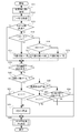
- step S4 details of the dimming control process in step S4 will be described with reference to FIG.
- step S11 the CPU 81 acquires an illuminance detection value x indicating the illuminance of the external light N from the optical sensor 70 via the A / D converter 85.
- the illuminance detection value x is stored in the RAM 82 for a total of four times for the current time and the past three times.
- step S12 the CPU 81 performs a simple moving averaging process on the four detected illuminance values x including the current time, and calculates the current average illuminance value X.
- the number of samplings is four, but the number of samplings is arbitrary.
- step S13 the CPU 81 determines whether or not a set time t (for example, 300 msec) set by the timer has elapsed since the previous determination of illuminance change (described later). If the set time t has elapsed (step S13; Yes), the process proceeds to step S14. If the set time t has not elapsed (step S13; No), the process proceeds to step S19.
- a set time t for example, 300 msec
- step S14 the CPU 81 determines the absolute value of the difference between the average illuminance value X0 at the previous determination (that is, before the set time t) stored in the RAM 82 and the current average illuminance value X from a predetermined threshold value h. If the absolute value of the difference between the two is smaller than the threshold value h (
- step S15 the CPU 81 sets the type of the determination result of the current illuminance change in step S14 to “same” indicating that there is no change in ambient illuminance (no illuminance change). Thereafter, the CPU 81 proceeds to step S19.
- step S16 the CPU 81 determines whether or not the average illuminance value X0 at the previous determination is greater than the current average illuminance value X, and the average illuminance value X0 at the previous determination is greater than the current average illuminance value X (X0). > X, step S16; Yes), the process proceeds to step S17. If the average illuminance value X0 at the previous determination is smaller than the current average illuminance value X (X0 ⁇ X, step S16; No), the process proceeds to step S18. Transition.
- step S17 the CPU 81 sets the type of the current illuminance change determination result in step S14 to “low” indicating that the ambient illuminance has decreased (illuminance decrease). Thereafter, the CPU 81 proceeds to step S19.
- step S18 the CPU 81 sets the type of the current illuminance change determination result in step S14 to “high” indicating that the ambient illuminance has increased (illuminance increase). Thereafter, the CPU 81 proceeds to step S19.
- step S ⁇ b> 19 the CPU 81 continuously determines the state of the determination result of the illuminance change for three times including the current time (“same”, “same”, “same” or “low”, “low”, “low”). Or “high”, “high”, or “high”), and if the state is the same type for three consecutive times (step S19; Yes), the process proceeds to step S20. When the same kind of state is not continued three times (step S19; No), the process proceeds to step S26. In addition, the case where the state is the same kind continuously for more than three times is included in the case where the state is the same kind three times continuously.
- step S20 the CPU 81 determines whether or not the state type of the determination result of three consecutive illuminance changes is “high”. If the state type is “high” (step S20; Yes). The process proceeds to step S21, and if the state type is not “high” (step S20; No), the process proceeds to step S22.
- step S21 the CPU 81 determines whether or not the current average illuminance value X is larger than the currently set target reference value Y. If the current average illuminance value X is larger than the target reference value Y ( In step S21; Yes, the process proceeds to step S25. If the current average illuminance value X is equal to or less than the target reference value Y (step S21; No), the process proceeds to step S26.
- step S22 the CPU 81 determines whether or not the state type of the determination result of three consecutive illuminance changes is “low”, and when the state type is “low” (step S22; Yes). The process proceeds to step S23, and if the status type is not “low” (step S22; No), the process proceeds to step S24.
- step S23 the CPU 81 determines whether or not the current average illuminance value X is smaller than the currently set target reference value Y. If the current average illuminance value X is smaller than the target reference value Y ( In step S23; Yes, the process proceeds to step S25. When the current average illuminance value X is equal to or greater than the target reference value Y (step S23; No), the process proceeds to step S26.
- step S24 the CPU 81 determines whether or not the state of the determination result of the illuminance change for 50 times including the current time is “same” continuously, and the state is “same” for 50 times continuously. (Step S24; Yes) proceeds to step S25, and if the state is not “same” for 50 consecutive times (step S24; No), the process proceeds to step S26. In addition, the case where the state is the same kind continuously for more than 50 times is included in the case where the state is the same kind continuously for 50 times.
- step S25 the CPU 81 updates the target reference value Y, and sets the current average illuminance value X as a new target reference value Y. Thereafter, the CPU 81 proceeds to step S26.
- step S26 the CPU 81 reads a target luminance value Pt corresponding to the set target reference value Y, and further calculates an output luminance value Pn based on the target luminance value Pt.
- the CPU 81 includes a plurality of target reference values Y and a plurality of target luminance values Pt corresponding to each of the target reference values Y, and refers to a data table stored in the ROM 83 to set the current setting. A target luminance value Pt corresponding to the target reference value Y being determined is determined.
- This formula calculates the increment of the luminance value by dividing the difference between the target luminance value Pt and the previous output luminance value Po by the coefficient a, and adds this increment to the previous output luminance value Po.
- An output luminance value Pn is obtained.
- the reason why the current output brightness value Pn is calculated in this way is that when the previous output brightness value Po is directly changed to the target brightness value Pt, a sudden brightness change occurs, which hinders the observer 2.
- the coefficient a does not always have to be constant, and different values may be used depending on whether the display luminance is increased or decreased. Generally, bright adaptation requires less time than dark adaptation.
- the value of the coefficient a is decreased to shorten the time until the target luminance value Pt is reached, and the display luminance is reduced.
- luminance adjustment suitable for the characteristics of human eyes can be realized.
- the CPU 81 determines the illuminance change at each set time t. Then, if the state of the determination result of the illuminance change is “high” three times in succession, the average of this time until the next determination is performed (that is, until the set time t that becomes No at Step S13). Only when the illuminance value X is larger than the target reference value Y, the target reference value Y is updated to the current average illuminance value X, and the display brightness is adjusted based on the target reference value Y (that is, the current average illuminance value X). Do.
- the average illuminance value X is calculated in a cycle (for example, 100 msec) shorter than the set time t in accordance with the display image update cycle. Further, if the state of the determination result of the illuminance change is “low” three times in succession, the target reference value Y is changed to the current average illuminance value X only when the current average illuminance value X is smaller than the target reference value Y. The display brightness is adjusted based on the target reference value Y (that is, the current average illuminance value X).
- the target reference value Y is updated to the current average illuminance value X, and the target reference value Y (that is, the current average illuminance value X ) To adjust the display brightness.
- the target reference value Y is not updated, and the display brightness is adjusted based on the target reference value Y (that is, not the current average illuminance value X but the previous average illuminance value).
- the display luminance is adjusted so as to continuously approach the target luminance value Pt, and the previous output luminance value Po is already set to the target luminance value Pt. If it has reached, display brightness will be maintained.
- the CPU 81 of the control means 80 calculates the current average illuminance value X (current illuminance value) calculated based on the detection result (illuminance detection value x) of the optical sensor 70.
- the average illuminance value X0 at the previous determination (illuminance value at the previous determination) is less than a predetermined threshold value h, it is determined that there is no illuminance change (
- the HUD device 1 is determined when the CPU 81 of the control means 80 determines that there is no illuminance change 50 times (second number) (step S24; Yes).
- the display brightness of the display device 20 is adjusted according to the current average illuminance value X (steps S25 and S26).
- the determination is made for a certain period (50 determinations in this embodiment).
- the display brightness can be corrected to the actual illuminance at every necessary time). In this case, since the display may flicker if the correction period is short, it is desirable to set the period relatively long.
- the CPU 81 of the control unit 80 calculates the average illuminance value X at a cycle shorter than the cycle (set time t) for determining the illuminance change, and changes the illuminance. It is determined whether the determination result state is no change in illuminance (“same”), increased illuminance (“high”), or decreased illuminance (“low”) (steps S14 to S18).
- the state of change of the average illuminance value X (the magnitude of the average illuminance value X relative to the target reference value Y) matches the state of the determination result of the illuminance change (continuous illuminance change If the determination result state is “high”, X> Y, and if it is “low”, if X ⁇ Y, only in steps S20 to S23), the display 20 Is adjusted (steps S25, S). 6) is intended.
- an indicator that is based on the current average illuminance value X that is calculated during that time when it is determined that there is an illuminance change three times in succession (the current average illuminance value X is updated to the target reference value Y).
- the output luminance value Pn may not be stable and display may flicker.
- the present embodiment is the HUD device 1 that allows the observer 2 to visually recognize the virtual image V of the display image
- the present invention may be applied to a direct-view type display device in which the observer directly recognizes the display image.
- the present invention is particularly effective for an in-vehicle display device in which the illuminance change around the display image is drastic, but other than the in-vehicle device as long as the display device is assumed to be used in an environment where the ambient illuminance changes. Can be applied.
- the present invention can be applied to a display device capable of adjusting the display brightness of a light-emitting display device according to ambient illuminance and a control method thereof.
- HUD device display device
- observer case body
- indicator light emitting indicator
- Circuit board 40
- Reflective member 50
- Combiner 60
- Light guide 70
- control means 81
- CPU 82
- RAM 83
- ROM 84
- Data I / O circuit 85
- a / D converter 86
- Drive circuit L Display light N External light V Virtual image
Landscapes
- Engineering & Computer Science (AREA)
- Physics & Mathematics (AREA)
- Computer Hardware Design (AREA)
- General Physics & Mathematics (AREA)
- Theoretical Computer Science (AREA)
- Control Of Indicators Other Than Cathode Ray Tubes (AREA)
- Circuit Arrangement For Electric Light Sources In General (AREA)
- Instrument Panels (AREA)
Abstract
表示輝度の調整の応答性を低下させることなく表示輝度の変更による表示のちらつきを低減することが可能な表示装置及びその制御方法を提供する。表示輝度を変更可能な発光表示器(表示器)(20)と、周囲の照度を検出する照度検出手段(光センサ)(70)と、照度検出手段(70)の検出結果に基づいて算出される照度値に応じて発光表示器(20)の表示輝度を調整する制御手段(80)と、を備えてなる表示装置(HUD装置)(1)である。制御手段(80)は、今回の照度値と前回判定時の照度値との差の絶対値が所定の閾値未満である場合は照度変化がないと判定し、前記今回の照度値と前記前回判定時の照度値との差の絶対値が前記閾値以上である場合は照度変化があると判定し、所定の第一の回数連続して照度変化があると判定される場合に、前記今回の照度値に応じて前記発光表示器の表示輝度を調整する。
Description
本発明は、周囲の照度に応じて発光表示器の表示輝度を調整可能な表示装置及びその制御方法に関するものである。
従来より、蛍光表示管等の発光表示器の輝度を周囲の照度に応じて自動調整する表示装置が知られている。例えば、車両に搭載されるヘッドアップディスプレイにおいては、車両のフロントガラス上に投影される表示像の背景となる車両前方の照度を光センサで検出し、この検出した車両前方の照度に応じてフロントガラス上に投影される表示像の輝度を制御し、これにより照度が高くなる(明るくなる)場合には、表示輝度を高くし、また照度が小さくなる(暗くなる)場合には、表示輝度を低くして、表示輝度が周囲の照度に対して最適化されるように調整するものがある(例えば、特許文献1参照)。
また、かかる発光表示器の自動調整においては、車両の走行中に外光が所々入ってくるような場合やワイパーが動作している場合などに光センサの照度検出値に一時的かつ突発的な変化が生じることがあり、このような照度検出値のノイズ成分に応じて表示輝度を調整すると表示輝度の変化が短時間に繰り返されて表示にちらつきが生じるという問題がある。これに対し、特許文献2には、照度検出値に基づく照度変化の判定を複数回行い、所定回数連続して照度変化があると判定された場合に最新の照度検出値に基づいて表示輝度を調整する表示装置が開示されている。
しかしながら、特許文献2に開示される構成は、一時的かつ突発的な照度検出値の変化に対してはちらつきを低減できるものの、微小な変化であっても照度変化があると判定されるため、照度検出値の微小なバラツキが連続する場合にはちらつきの発生を防止できないという問題点があった。これに対しては照度変化の判定回数を増加することで対応する余地はあるが、この場合は輝度調整の応答性が悪くなるという別の問題が生じる。日中などの周囲の照度が高い場合においては照度検出値の微小なバラツキに応じて表示輝度が変更されても利用者にはちらつきが認識されにくいが、日の出時や薄暮時などの周囲の照度が低い場合においては表示像と背景とのコントラストが高いため、ちらつきが認識されやすい。
そこで、本発明は、上述した課題に着目してなされたものであり、表示輝度の調整の応答性を低下させることなく表示輝度の変更による表示のちらつきを低減することが可能な表示装置及びその制御方法を提供することを目的とするものである。
本発明は、前記課題を解決するため、表示輝度を変更可能な発光表示器と、周囲の照度を検出する照度検出手段と、前記照度検出手段の検出結果に基づいて算出される照度値に応じて前記発光表示器の表示輝度を調整する制御手段と、を備えてなる表示装置であって、
前記制御手段は、今回の照度値と前回判定時の照度値との差の絶対値が所定の閾値未満である場合は照度変化がないと判定し、前記今回の照度値と前記前回判定時の照度値との差の絶対値が前記閾値以上である場合は照度変化があると判定し、所定の第一の回数連続して照度変化があると判定される場合に、前記今回の照度値に応じて前記発光表示器の表示輝度を調整することを特徴とする。
前記制御手段は、今回の照度値と前回判定時の照度値との差の絶対値が所定の閾値未満である場合は照度変化がないと判定し、前記今回の照度値と前記前回判定時の照度値との差の絶対値が前記閾値以上である場合は照度変化があると判定し、所定の第一の回数連続して照度変化があると判定される場合に、前記今回の照度値に応じて前記発光表示器の表示輝度を調整することを特徴とする。
また、前記制御手段は、前記第一の回数よりも多い第二の回数連続して照度変化がないと判定された場合に、前記今回の照度値に応じて前記発光表示器の表示輝度を調整することを特徴とする。
また、前記制御手段は、前記照度値を照度変化の判定をする周期よりも短い周期で算出し、照度変化の判定結果の状態が照度変化なし、照度上昇あるいは照度低下のいずれであるかを判定し、前記第一の回数連続して照度変化があると判定されている間は前記照度値の変化の状態が前記照度変化の判定結果の状態と一致する場合にのみ前記今回の照度値に応じて前記発光表示器の表示輝度を調整することを特徴とする。
本発明は、前記課題を解決するため、表示輝度を変更可能な発光表示器と、周囲の照度を検出する照度検出手段と、を備え、前記照度検出手段の検出結果に基づいて算出される照度値に応じて前記発光表示器の表示輝度を調整する表示装置の制御方法であって、
今回の照度値と前回判定時の照度値との差の絶対値が所定の閾値未満である場合は照度変化がないと判定し、前記今回の照度値と前記前回判定時の照度値との差の絶対値が前記閾値以上である場合は照度変化があると判定し、所定の第一の回数連続して照度変化があると判定される場合に、前記今回の照度値に応じて前記発光表示器の表示輝度を調整することを特徴とする。
今回の照度値と前回判定時の照度値との差の絶対値が所定の閾値未満である場合は照度変化がないと判定し、前記今回の照度値と前記前回判定時の照度値との差の絶対値が前記閾値以上である場合は照度変化があると判定し、所定の第一の回数連続して照度変化があると判定される場合に、前記今回の照度値に応じて前記発光表示器の表示輝度を調整することを特徴とする。
また、前記第一の回数よりも多い第二の回数連続して照度変化がないと判定された場合に、前記今回の照度値に応じて前記発光表示器の表示輝度を調整することを特徴とする。
また、前記照度値を照度変化の判定をする周期よりも短い周期で算出し、照度変化の判定結果の状態が照度変化なし、照度上昇あるいは照度低下のいずれであるかを判定し、前記第一の回数連続して照度変化があると判定されている間は前記照度値の変化の状態が前記照度変化の判定結果の状態と一致する場合にのみ前記今回の照度値に応じて前記発光表示器の表示輝度を調整することを特徴とする。
本発明によれば、表示輝度の調整の応答性を低下させることなく表示輝度の変更による表示のちらつきを低減することが可能となる。
以下、本発明を車両用のヘッドアップディスプレイ(Head-Up Display;HUD)装置に適用した一実施形態を添付図面に基づいて説明する。
まず、図1を用いてHUD装置1の基本的な構成を説明する。HUD装置1は、ケース体10と、表示器(発光表示器)20と、回路基板30と、反射部材40と、コンバイナ50と、コンバイナ50と一体的に形成された導光体60と、光センサ(照度検出手段)70と、を備える。
HUD装置1は、例えば、車両のダッシュボード上(例えば、インストルメントパネル上方)に取り付けられる据え置き型のHUD装置として構成されている。以下の説明では、HUD装置1が表示する表示画像を視認する観察者2からみて、上方向を「上」、下方向を「下」、前方向を「前」、後ろ方向を「後」として(図1の両端矢印参照)、適宜、HUD装置1を構成する各部を説明する。
HUD装置1は、例えば、車両のダッシュボード上(例えば、インストルメントパネル上方)に取り付けられる据え置き型のHUD装置として構成されている。以下の説明では、HUD装置1が表示する表示画像を視認する観察者2からみて、上方向を「上」、下方向を「下」、前方向を「前」、後ろ方向を「後」として(図1の両端矢印参照)、適宜、HUD装置1を構成する各部を説明する。
ケース体10は、遮光性の樹脂材料等からなる箱形状の部材であり、表示器20、回路基板30、反射部材40及び光センサ70を収納し、また、コンバイナ50を保持する。また、ケース体10の上部には、表示器20から発せられる表示光Lを通過させる第一の開口部11が形成されている。第一の開口部11よりも前方側にはコンバイナ50が取り付けられる部分である被取付部(図示しない)を有し、例えばネジによって前記被取付部にコンバイナ50の下端部が取り付けられている。このようにして、ケース体10はコンバイナ50を保持している。保持されたコンバイナ50は、ケース体10から上方に延出するような格好となる。また、ケース体10には、導光体60を上方に露出させるとともに、入射した光(後述する外光N)をケース体10内部に通過させるための第二の開口部12が形成されている。
表示器20は、車速、エンジン回転数、シフトポジション、走行距離、残燃料量、時刻、燃費、外部温度等の表示情報を含む表示画像を表す表示光Lを出射する発光表示器であり、例えばLED(Light Emitting Diode)をマトリクス状に配置したLED表示器や液晶パネルとバックライト用光源から構成される透過型液晶ディスプレイ、あるいは有機ELディスプレイ等からなる。表示器20は、後述する調光制御によって外光Nの照度に応じて表示光Lの輝度(表示輝度)を調整可能なものである。
回路基板30は、ガラス繊維を含む樹脂等からなる板状の基材に、光センサ70や後述する制御手段80(図1においては図示しない)等を表面に実装し、部品間を配線したプリント回路基板である。回路基板30は、ケース体10内部の表示器20よりも前側に図示しない取付部材によって固定される。回路基板30と表示器20とはFPC(Flexible Printed Circuit)3を介して導通接続されている。FPC3の一端部はコネクタCを介して回路基板30と接続されている。
反射部材40は、例えばアルミ蒸着された板状の樹脂成型品からなり、表示器20の表示側、すなわち表示光Lの出射側に位置し、到達した表示光Lをコンバイナ50に向けて反射するものである。また、反射部材40は、表示画像の拡大や歪みの補正のために曲面として構成された反射面を有する(なお、図1においては反射面を概略的に平面のように表している)。反射部材40は、その反射面が表示器20の表示側と略対向するように配置されている。表示器20から反射部材40に到達した表示光Lは、反射部材40の反射面で反射され、ケース体10の第一の開口部11を通過してコンバイナ50に向かう。
コンバイナ50は、曲面状の反射面を有する板状のハーフミラー等により構成される(なお、図1においてはコンバイナ50を概略的に平面のように表している)。前述のように、コンバイナ50は、ケース体10に取り付けられており、その反射面が反射部材40の反射面と略対向する。コンバイナ50は、到達した表示光Lを反射面で観察者2に向けて反射し、表示光Lを観察者2の目に入射させて観察者2にコンバイナ50の前方に形成される表示画像の虚像Vを視認させる。これにより、観察者2は前方の実体である風景と虚像Vとの双方を重ねて視認することができる。なお、コンバイナ50としてホログラム素子を用いてもよく、この場合はコンバイナ50に到達した表示光Lは回折によって光路変更される。
導光体60は、コンバイナ50と一体的に形成されてなり、例えば、コンバイナ50の下端部の一部から下方に突出形成される。導光体60は、所定の方向(本実施形態においては主に前方)からの外光Nを光センサ70に導くものであり、上向きに傾斜し外光Nを入射する入射面61と、光センサ70に向けて外光Nを出射する出射面62と、を有して形成されている。
光センサ70は、到達した光の明るさ(照度)を検出するためのものであり、導光体60の出射面62と対向し、かつ、光センサ70に入射する光の光軸が上下方向に沿うように回路基板30上に配設されている。光センサ70は、到達した光の照度に応じた電圧を増幅回路(図示しない)を介して制御手段に供給する。
図2は、HUD装置1の電気的構成を示す図である。制御手段80は、CPU(Central Processing Unit)81と、RAM(Random Access Memory)82と、ROM(Read Only Memory)83と、データI/O回路84と、A/D変換器85と、駆動回路86と、これらを接続するバスライン等からなる周知のマイクロコンピュータを中心に構成される回路である。
CPU81は、他の各部82~86と接続され、各種演算処理によって表示器20の表示制御や調光制御を行うものである。
RAM82は、CPU81における演算処理結果を一時記憶する読み出し及び書き換え可能なワークメモリとして機能するものである。
ROM83は、CPU81を動作させるプログラム等が記憶されるものである。
データI/O回路84は、CAN(Controller Area Network)と称される相互接続された機器間のデータ通信仕様に基づいて、車両側の各種システムと車両情報(車速やエンジン回転数等の各種検出信号)を取得するものである。
A/D変換器85は、光センサ70から出力されたアナログ電圧をデジタル値(照度検出値)に変換してCP81に出力するものである。
駆動回路86は、CPU81からの制御信号に応じて表示器20に駆動電流を出力し、表示器20の表示内容の変更や表示光Lの輝度調整を行う。
次に、図3及び図4を用いてHUD装置1の制御方法について説明する。
まず、図3はHUD装置1の表示制御処理全体のフローチャートを示している。
まず、図3はHUD装置1の表示制御処理全体のフローチャートを示している。
CPU81は、車両のバッテリラインの接続などによってマイクロコンピュータに電源が投入されると、まず、ステップS1において各種機能の初期設定を行う。
次に、CPU81は、ステップS2において、駆動回路86への電源供給を行う。
次に、CPU81は、ステップS3において、データI/O回路84を介して車両側より前記車両情報を受信し、前記車両情報に基づいて表示器20に表示する表示画像データを作成する。
次に、CPU81は、ステップS4において、後で詳述する調光制御処理によって今回の出力輝度値Pnを決定する。
次に、CPU81は、ステップS5において、ステップS4で決定した今回の出力輝度値Pnを駆動回路86に出力する。駆動回路86は出力輝度値Pnに応じて表示器20を例えばPWM制御し、表示光Lの輝度を調整する。
次に、CPU81は、ステップS6において、ステップS3において作成した表示画像データを駆動回路86に出力する。駆動回路86は表示画像データに応じて表示器20の表示内容を変更して、任意の表示画像を表示させる。
CPU81は、以後ステップS3~S6までの処理を電源が供給されなくなるまで繰り返し行う。
次に、図4を用いて、ステップS4における調光制御処理の詳細を説明する。
まず、CPU81は、ステップS11において、光センサ70からA/D変換器85を介して外光Nの照度を示す照度検出値xを取得する。なお、照度検出値xは、今回分と過去3回分の合計4回分がRAM82に保持される。
次に、CPU81は、ステップS12において、前述した今回分を含む4回分の照度検出値xについて単純移動平均化処理を行い、今回の平均照度値Xを算出する。なお、本実施形態においてはサンプリング数は4回であったが、サンプリング数は任意である。
次に、CPU81は、ステップS13において、前回の照度変化の判定(後述する)からタイマ設定された設定時間t(例えば300msec)が経過したか否かを判定する。設定時間tが経過している場合(ステップS13;Yes)は、ステップS14に移行し、設定時間tが経過していない場合(ステップS13;No)は、ステップS19に移行する。
ステップS14において、CPU81は、RAM82に記憶されている前回判定時の(すなわち、設定時間t前の)平均照度値X0と今回の平均照度値Xとの差の絶対値が予め定められる閾値hより小さいか否かを判定し、両者の差の絶対値が閾値hより小さい場合(|X0-X|<h、ステップS14;Yes)は照度変化がないと判定してステップS15に移行し、両者の差が閾値h以上である(|X0-X|≧h、ステップS14;No)場合は照度変化があると判定してステップS16に移行する。
ステップS15において、CPU81は、ステップS14における今回の照度変化の判定結果の状態の種別を周囲照度に変化がない(照度変化なし)状態を示す「同」とする。その後、CPU81は、ステップS19に移行する。
ステップS16において、CPU81は、前回判定時の平均照度値X0が今回の平均照度値Xより大きいか否かを判定し、前回判定時の平均照度値X0が今回の平均照度値Xより大きい(X0>X、ステップS16;Yes)場合は、ステップS17に移行し、前回判定時の平均照度値X0が今回の平均照度値Xより小さい(X0<X、ステップS16;No)場合は、ステップS18に移行する。
ステップS17において、CPU81は、ステップS14における今回の照度変化の判定結果の状態の種別を周囲照度が低下した(照度低下)状態を示す「低」とする。その後、CPU81は、ステップS19に移行する。
ステップS18において、CPU81は、ステップS14における今回の照度変化の判定結果の状態の種別を周囲照度が上昇した(照度上昇)状態を示す「高」とする。その後、CPU81は、ステップS19に移行する。
ステップS19において、CPU81は、今回分を含む3回分の照度変化の判定結果の状態が連続して同種(「同」、「同」、「同」か「低」、「低」、「低」か「高」、「高」、「高」かのいずれか)であるか否かを判定し、状態が3回連続して同種である場合(ステップS19;Yes)はステップS20に移行し、同種の状態が3回連続しない場合(ステップS19;No)はステップS26に移行する。なお、状態が3回より多く連続して同種である場合も3回連続して同種である場合に含まれる。
ステップS20において、CPU81は、3回連続した照度変化の判定結果の状態の種別が「高」であるか否かを判定し、状態の種別が「高」である場合(ステップS20;Yes)はステップS21に移行し、状態の種別が「高」でない場合(ステップS20;No)はステップS22に移行する。
ステップS21において、CPU81は、今回の平均照度値Xが、現在設定されている目標基準値Yよりも大きいか否かを判定し、今回の平均照度値Xが目標基準値Yよりも大きい場合(ステップS21;Yes)は、ステップS25に移行し、今回の平均照度値Xが目標基準値Y以下である場合は(ステップS21;No)は、ステップS26に移行する。
ステップS22において、CPU81は、3回連続した照度変化の判定結果の状態の種別が「低」であるか否かを判定し、状態の種別が「低」である場合(ステップS22;Yes)はステップS23に移行し、状態の種別が「低」でない場合(ステップS22;No)はステップS24に移行する。
ステップS23において、CPU81は、今回の平均照度値Xが、現在設定されている目標基準値Yよりも小さいか否かを判定し、今回の平均照度値Xが目標基準値Yよりも小さい場合(ステップS23;Yes)は、ステップS25に移行し、今回の平均照度値Xが目標基準値Y以上である場合は(ステップS23;No)は、ステップS26に移行する。
ステップS24において、CPU81は、今回分を含む50回分の照度変化の判定結果の状態が連続して「同」であるか否かを判定し、状態が50回連続して「同」である場合(ステップS24;Yes)はステップS25に移行し、状態が50回連続して「同」でない場合(ステップS24;No)はステップS26に移行する。なお、状態が50回より多く連続して同種である場合も50回連続して同種である場合に含まれる。
ステップS25において、CPU81は、目標基準値Yの更新を行い、今回の平均照度値Xを新たな目標基準値Yとする。その後、CPU81は、ステップS26に移行する。
ステップS26において、CPU81は、設定されている目標基準値Yに対応する目標輝度値Ptを読み出し、さらに目標輝度値Ptに基づいて出力輝度値Pnを算出する。
具体的には、まず、CPU81は、複数の目標基準値Yと目標基準値Yの各々に対応する複数の目標輝度値Ptとからなり、ROM83に記憶されるデータテーブルを参照して、現在設定されている目標基準値Yに対応する目標輝度値Ptを決定する。なお、このデータテーブルにおける目標基準値Yと目標輝度値Ptとの対応関係は、目標輝度値Ptが、目標基準値Y、すなわち周囲照度に対して観察者2が表示画像(虚像V)を視認しやすい値となるように定められる。
そして、CPU81は、前回の出力輝度値Poから決定された目標輝度値Ptに対して一定の割合で近づかせるように今回の出力輝度値Pnを算出する。具体的には、Pn=Po+(Pt-Po)/a(aは係数)で示される式によって今回の出力輝度値Pnを得る。この式は、目標輝度値Ptと前回の出力輝度値Poとの差分を係数aで除して輝度値の増加分を算出し、この増加分を前回の出力輝度値Poに加算して今回の出力輝度値Pnを得るものである。このようにして今回の出力輝度値Pnを算出するのは、前回の出力輝度値Poから目標輝度値Ptに直接変化させると急激な輝度変化が生じ、観察者2の妨げとなるためである。なお、係数aは常に一定である必要はなく、表示輝度を上昇させる場合と低下させる場合とで異なる値を用いてもよい。一般的に、明順応は暗順応よりも必要とする時間が短いため、表示輝度を上昇させる場合は係数aの値を小さくして目標輝度値Ptに達するまでの時間を短くし、表示輝度を低下させる場合は係数aの値を大きくして目標輝度値Ptに達するまでの時間を長くすることで、人間の目の特性に適合した輝度調整を実現できる。
以上の処理を実行することによって、CPU81は、設定時間t毎に照度変化の判定を行う。そして、照度変化の判定結果の状態が3回連続して「高」であると、次の判定を行うまでの間(すなわちステップS13;Noとなる設定時間t経過までの間)、今回の平均照度値Xが目標基準値Yより大きい場合にのみ目標基準値Yを今回の平均照度値Xに更新して、目標基準値Y(すなわち今回の平均照度値X)に基づいて表示輝度の調整を行う。なお、平均照度値Xの算出は、表示画像の更新周期に合わせて設定時間tよりも短い周期(例えば100msec)で行われる。また、照度変化の判定結果の状態が3回連続して「低」であると、今回の平均照度値Xが目標基準値Yより小さい場合にのみ目標基準値Yを今回の平均照度値Xに更新して、目標基準値Y(すなわち今回の平均照度値X)に基づいて表示輝度の調整を行う。また、照度変化の判定結果の状態が50回連続して「同」であると、目標基準値Yを今回の平均照度値Xに更新して、目標基準値Y(すなわち今回の平均照度値X)に基づいて表示輝度の調整を行う。上記以外の場合は、目標基準値Yの更新は行われず、目標基準値Y(すなわち今回の平均照度値Xでなく、それ以前の平均照度値)に基づいて表示輝度の調整を行う。この場合、前回の出力輝度値Poが目標輝度値Ptに達していなければ継続して目標輝度値Ptに近づくように表示輝度の調整が行われ、既に前回の出力輝度値Poが目標輝度値Ptに達していれば表示輝度が維持されることとなる。
本実施形態であるHUD装置1及びその制御方法は、制御手段80のCPU81により、光センサ70の検出結果(照度検出値x)に基づいて算出される今回の平均照度値X(今回の照度値)と前回判定時の平均照度値X0(前回判定時の照度値)との差の絶対値が所定の閾値h未満である場合は照度変化がないと判定し(|X0-X|<h、ステップS14;Yes)、今回の平均照度値Xと前回判定時の平均照度値X0との差の絶対値が閾値h以上である場合は照度変化があると判定し(|X0-X|≧h、ステップS14;No)、3回(第一の回数)連続して照度変化があると判定される場合に、今回の平均照度値Xに応じて表示器20の表示輝度を調整する(ステップS25、S26)ものである。
これによって、照度検出値xの微小なバラツキが連続する場合であっても、閾値hによって微小なバラツキによる変化を照度変化があるとの判定から除外することができ、表示輝度の調整の応答性を低下させることなく表示輝度の変更による表示のちらつきを低減することが可能となる。
これによって、照度検出値xの微小なバラツキが連続する場合であっても、閾値hによって微小なバラツキによる変化を照度変化があるとの判定から除外することができ、表示輝度の調整の応答性を低下させることなく表示輝度の変更による表示のちらつきを低減することが可能となる。
さらに、本実施形態であるHUD装置1及びその制御方法は、制御手段80のCPU81により、50回(第二の回数)連続して照度変化がないと判定された場合(ステップS24;Yes)に、今回の平均照度値Xに応じて表示器20の表示輝度を調整する(ステップS25、S26)ものである。
これによって、閾値hの範囲内で徐々に照度変化が生じ、実際の周囲の照度と表示輝度とが適合しなくなる場合があっても、一定周期(本実施形態では50回の判定を行うのに必要な時間毎)に実際の照度に適した表示輝度に修正することができる。なお、この場合、修正の周期が短いと表示のちらつきとなるおそれがあるため、周期を比較的長く設定することが望ましい。
これによって、閾値hの範囲内で徐々に照度変化が生じ、実際の周囲の照度と表示輝度とが適合しなくなる場合があっても、一定周期(本実施形態では50回の判定を行うのに必要な時間毎)に実際の照度に適した表示輝度に修正することができる。なお、この場合、修正の周期が短いと表示のちらつきとなるおそれがあるため、周期を比較的長く設定することが望ましい。
また、本実施形態であるHUD装置1及びその制御方法は、制御手段80のCPU81により、平均照度値Xを照度変化の判定をする周期(設定時間t)よりも短い周期で算出し、照度変化の判定結果の状態が照度変化なし(「同」)、照度上昇(「高」)あるいは照度低下(「低」)のいずれであるかを判定し(ステップS14~S18)、3回連続して照度変化があると判定されている間は平均照度値Xの変化の状態(平均照度値Xの目標基準値Yに対する大小)が照度変化の判定結果の状態と一致する場合(連続する照度変化の判定結果の状態が「高」であればX>Yである場合、「低」であればX<Yである場合、ステップS20~S23)にのみ今回の平均照度値Xに応じて表示器20の表示輝度を調整する(ステップS25、S26)ものである。
従来、3回連続して照度変化があると判定されている間に単にその間算出される今回の平均照度値Xに応じた(今回の平均照度値Xを目標基準値Yに更新した)表示器20の表示輝度の調整を行うと、平均照度値Xにバラツキが生じる場合に出力輝度値Pnが安定せず、表示のちらつきとなる場合がある。これに対し、上記のようにすることで、照度変化の判定結果の状態と異なる平均照度値Xの変化があっても、表示輝度の調整を行う基準として採用されないため(目標基準値Yに更新されないため)、照度変化の判定がされる間の出力輝度値Pnを安定化させ、表示のちらつきを抑制することが可能となる。
従来、3回連続して照度変化があると判定されている間に単にその間算出される今回の平均照度値Xに応じた(今回の平均照度値Xを目標基準値Yに更新した)表示器20の表示輝度の調整を行うと、平均照度値Xにバラツキが生じる場合に出力輝度値Pnが安定せず、表示のちらつきとなる場合がある。これに対し、上記のようにすることで、照度変化の判定結果の状態と異なる平均照度値Xの変化があっても、表示輝度の調整を行う基準として採用されないため(目標基準値Yに更新されないため)、照度変化の判定がされる間の出力輝度値Pnを安定化させ、表示のちらつきを抑制することが可能となる。
以上の説明は本発明を例示するものであって、その要旨を逸脱しない範囲で種々の変更、変形が可能であることは言うまでもない。本実施形態は表示画像の虚像Vを観察者2に視認させるHUD装置1であったが、表示画像を観察者が直接視認する直視型の表示装置に本発明を適用してもよい。また、本発明は表示画像の周囲の照度変化が激しい車載用の表示装置に特に効果を奏するが、周囲照度が変化する環境下での使用が想定される表示装置であれば車載用以外にも適用することができる。
本発明は、周囲の照度に応じて発光表示器の表示輝度を調整可能な表示装置及びその制御方法に適用可能である。
1 HUD装置(表示装置)
2 観察者
10 ケース体
20 表示器(発光表示器)
30 回路基板
40 反射部材
50 コンバイナ
60 導光体
70 光センサ(照度検出手段)
80 制御手段
81 CPU
82 RAM
83 ROM
84 データI/O回路
85 A/D変換器
86 駆動回路
L 表示光
N 外光
V 虚像
2 観察者
10 ケース体
20 表示器(発光表示器)
30 回路基板
40 反射部材
50 コンバイナ
60 導光体
70 光センサ(照度検出手段)
80 制御手段
81 CPU
82 RAM
83 ROM
84 データI/O回路
85 A/D変換器
86 駆動回路
L 表示光
N 外光
V 虚像
Claims (6)
- 表示輝度を変更可能な発光表示器と、周囲の照度を検出する照度検出手段と、前記照度検出手段の検出結果に基づいて算出される照度値に応じて前記発光表示器の表示輝度を調整する制御手段と、を備えてなる表示装置であって、
前記制御手段は、今回の照度値と前回判定時の照度値との差の絶対値が所定の閾値未満である場合は照度変化がないと判定し、前記今回の照度値と前記前回判定時の照度値との差の絶対値が前記閾値以上である場合は照度変化があると判定し、所定の第一の回数連続して照度変化があると判定される場合に、前記今回の照度値に応じて前記発光表示器の表示輝度を調整することを特徴とする表示装置。 - 前記制御手段は、前記第一の回数よりも多い第二の回数連続して照度変化がないと判定された場合に、前記今回の照度値に応じて前記発光表示器の表示輝度を調整することを特徴とする請求項1に記載の表示装置。
- 前記制御手段は、前記照度値を照度変化の判定をする周期よりも短い周期で算出し、照度変化の判定結果の状態が照度変化なし、照度上昇あるいは照度低下のいずれであるかを判定し、前記第一の回数連続して照度変化があると判定されている間は前記照度値の変化の状態が前記照度変化の判定結果の状態と一致する場合にのみ前記今回の照度値に応じて前記発光表示器の表示輝度を調整することを特徴とする請求項1または請求項2に記載の表示装置。
- 表示輝度を変更可能な発光表示器と、周囲の照度を検出する照度検出手段と、を備え、前記照度検出手段の検出結果に基づいて算出される照度値に応じて前記発光表示器の表示輝度を調整する表示装置の制御方法であって、
今回の照度値と前回判定時の照度値との差の絶対値が所定の閾値未満である場合は照度変化がないと判定し、前記今回の照度値と前記前回判定時の照度値との差の絶対値が前記閾値以上である場合は照度変化があると判定し、所定の第一の回数連続して照度変化があると判定される場合に、前記今回の照度値に応じて前記発光表示器の表示輝度を調整することを特徴とする表示装置の制御方法。 - 前記第一の回数よりも多い第二の回数連続して照度変化がないと判定された場合に、前記今回の照度値に応じて前記発光表示器の表示輝度を調整することを特徴とする請求項4に記載の表示装置の制御方法。
- 前記照度値を照度変化の判定をする周期よりも短い周期で算出し、照度変化の判定結果の状態が照度変化なし、照度上昇あるいは照度低下のいずれであるかを判定し、前記第一の回数連続して照度変化があると判定されている間は前記照度値の変化の状態が前記照度変化の判定結果の状態と一致する場合にのみ前記今回の照度値に応じて前記発光表示器の表示輝度を調整することを特徴とする請求項4または請求項5に記載の表示装置の制御方法。
Priority Applications (2)
| Application Number | Priority Date | Filing Date | Title |
|---|---|---|---|
| US14/398,949 US9251738B2 (en) | 2012-05-11 | 2013-04-05 | Display device and control method for same |
| EP13787320.4A EP2849175B1 (en) | 2012-05-11 | 2013-04-05 | Display device and control method for same |
Applications Claiming Priority (2)
| Application Number | Priority Date | Filing Date | Title |
|---|---|---|---|
| JP2012-109406 | 2012-05-11 | ||
| JP2012109406A JP6041121B2 (ja) | 2012-05-11 | 2012-05-11 | 表示装置及びその制御方法 |
Publications (1)
| Publication Number | Publication Date |
|---|---|
| WO2013168496A1 true WO2013168496A1 (ja) | 2013-11-14 |
Family
ID=49550549
Family Applications (1)
| Application Number | Title | Priority Date | Filing Date |
|---|---|---|---|
| PCT/JP2013/060438 WO2013168496A1 (ja) | 2012-05-11 | 2013-04-05 | 表示装置及びその制御方法 |
Country Status (4)
| Country | Link |
|---|---|
| US (1) | US9251738B2 (ja) |
| EP (1) | EP2849175B1 (ja) |
| JP (1) | JP6041121B2 (ja) |
| WO (1) | WO2013168496A1 (ja) |
Cited By (1)
| Publication number | Priority date | Publication date | Assignee | Title |
|---|---|---|---|---|
| CN110264927A (zh) * | 2019-06-18 | 2019-09-20 | 上海蔚来汽车有限公司 | Hud显示亮度的控制方法、装置、控制器和存储介质 |
Families Citing this family (13)
| Publication number | Priority date | Publication date | Assignee | Title |
|---|---|---|---|---|
| JP5556089B2 (ja) * | 2009-09-01 | 2014-07-23 | セイコーエプソン株式会社 | 画像表示装置および画像調整方法 |
| CN104267607A (zh) * | 2014-09-10 | 2015-01-07 | 京东方科技集团股份有限公司 | 调节室内光亮度的方法、装置和智能家居控制系统 |
| CN105404165B (zh) * | 2015-12-15 | 2018-05-15 | 意诺科技有限公司 | 一种控制面板及控制方法 |
| CN108463766B (zh) * | 2016-01-13 | 2021-02-12 | 凸版印刷株式会社 | 平视显示器装置 |
| FR3050541B1 (fr) * | 2016-04-26 | 2019-07-12 | Valeo Comfort And Driving Assistance | Afficheur |
| FR3050542B1 (fr) * | 2016-04-26 | 2019-07-12 | Valeo Comfort And Driving Assistance | Afficheur comprenant un capteur de lumiere |
| CN106774908A (zh) * | 2016-12-23 | 2017-05-31 | 杭州镜之镜科技有限公司 | 识别电子屏幕的方法及设备 |
| JP2019174519A (ja) * | 2018-03-27 | 2019-10-10 | 株式会社リコー | 表示装置、表示システム、移動体、表示輝度制御方法およびプログラム |
| EP3547299A3 (en) | 2018-03-27 | 2019-11-27 | Ricoh Company, Ltd. | Display device, display system, mobile object, display-brightness control method, and carrier means storing program code |
| FR3084476B1 (fr) * | 2018-07-30 | 2022-12-30 | Valeo Comfort & Driving Assistance | Afficheur capteur de lumiere |
| CN111045876A (zh) * | 2019-11-12 | 2020-04-21 | 广州视源电子科技股份有限公司 | 闪屏检测方法、装置、存储介质和电子设备 |
| DE102020125168B3 (de) | 2020-09-26 | 2022-03-03 | E-Lead Electronic Co., Ltd. | Head-Up-Display-Einrichtung und Betriebsverfahren davon |
| EP4311978A1 (en) * | 2022-07-28 | 2024-01-31 | Valeo Comfort and Driving Assistance | Display |
Citations (5)
| Publication number | Priority date | Publication date | Assignee | Title |
|---|---|---|---|---|
| JPS6142333U (ja) | 1984-08-22 | 1986-03-18 | 三菱自動車工業株式会社 | 車両用ヘツドアツプデイスプレイ |
| JP2004299506A (ja) | 2003-03-31 | 2004-10-28 | Nippon Seiki Co Ltd | 表示装置 |
| JP2004351943A (ja) * | 2003-03-31 | 2004-12-16 | Nippon Seiki Co Ltd | 表示装置 |
| JP2006285064A (ja) * | 2005-04-04 | 2006-10-19 | Matsushita Electric Ind Co Ltd | 画像表示装置 |
| JP2010054727A (ja) * | 2008-08-27 | 2010-03-11 | Sharp Corp | 映像表示装置 |
Family Cites Families (3)
| Publication number | Priority date | Publication date | Assignee | Title |
|---|---|---|---|---|
| US8373355B2 (en) * | 2006-11-09 | 2013-02-12 | Apple Inc. | Brightness control of a status indicator light |
| JP5556089B2 (ja) * | 2009-09-01 | 2014-07-23 | セイコーエプソン株式会社 | 画像表示装置および画像調整方法 |
| CN102959613B (zh) * | 2010-08-03 | 2015-06-03 | 夏普株式会社 | 显示控制方法、显示控制装置及液晶显示装置 |
-
2012
- 2012-05-11 JP JP2012109406A patent/JP6041121B2/ja not_active Expired - Fee Related
-
2013
- 2013-04-05 EP EP13787320.4A patent/EP2849175B1/en not_active Not-in-force
- 2013-04-05 WO PCT/JP2013/060438 patent/WO2013168496A1/ja active Application Filing
- 2013-04-05 US US14/398,949 patent/US9251738B2/en not_active Expired - Fee Related
Patent Citations (5)
| Publication number | Priority date | Publication date | Assignee | Title |
|---|---|---|---|---|
| JPS6142333U (ja) | 1984-08-22 | 1986-03-18 | 三菱自動車工業株式会社 | 車両用ヘツドアツプデイスプレイ |
| JP2004299506A (ja) | 2003-03-31 | 2004-10-28 | Nippon Seiki Co Ltd | 表示装置 |
| JP2004351943A (ja) * | 2003-03-31 | 2004-12-16 | Nippon Seiki Co Ltd | 表示装置 |
| JP2006285064A (ja) * | 2005-04-04 | 2006-10-19 | Matsushita Electric Ind Co Ltd | 画像表示装置 |
| JP2010054727A (ja) * | 2008-08-27 | 2010-03-11 | Sharp Corp | 映像表示装置 |
Cited By (1)
| Publication number | Priority date | Publication date | Assignee | Title |
|---|---|---|---|---|
| CN110264927A (zh) * | 2019-06-18 | 2019-09-20 | 上海蔚来汽车有限公司 | Hud显示亮度的控制方法、装置、控制器和存储介质 |
Also Published As
| Publication number | Publication date |
|---|---|
| US20150116192A1 (en) | 2015-04-30 |
| EP2849175B1 (en) | 2019-03-20 |
| EP2849175A4 (en) | 2016-05-18 |
| JP2013239243A (ja) | 2013-11-28 |
| US9251738B2 (en) | 2016-02-02 |
| EP2849175A1 (en) | 2015-03-18 |
| JP6041121B2 (ja) | 2016-12-07 |
Similar Documents
| Publication | Publication Date | Title |
|---|---|---|
| JP6041121B2 (ja) | 表示装置及びその制御方法 | |
| EP2473004B1 (en) | Brightness control of a status indicator light | |
| EP2905647B1 (en) | Laser scanning display device | |
| JP3646848B2 (ja) | 表示装置 | |
| JP2011093413A (ja) | 車両用表示装置 | |
| JP2004314860A (ja) | 表示装置 | |
| JP5842735B2 (ja) | 光源駆動装置及びヘッドアップディスプレイ装置 | |
| TWI426820B (zh) | 可調節發光亮度的照明裝置及調節方法 | |
| JP2004351943A (ja) | 表示装置 | |
| JP2008225438A (ja) | 車両用表示装置 | |
| WO2014034399A1 (ja) | 表示装置 | |
| US9008908B2 (en) | Head-up display and method with speed sensitive light intensity | |
| JP2004299506A (ja) | 表示装置 | |
| JP4241888B2 (ja) | 液晶表示装置 | |
| WO2012011337A1 (ja) | 車両用計器の照明装置 | |
| JP2012181466A (ja) | 液晶パネル装置 | |
| JP5982848B2 (ja) | 車両用表示装置 | |
| KR20100009227A (ko) | 헤드 업 디스플레이 장치 | |
| JP2009037000A (ja) | 液晶表示装置 | |
| KR20040110274A (ko) | 차량용 계기판의 조명 제어장치 및 그 방법 | |
| JP2005308895A (ja) | 液晶表示装置 | |
| JP2009042681A (ja) | 液晶表示装置 | |
| JP4295001B2 (ja) | 表示装置 | |
| JP2012066605A (ja) | 車両用照明調光装置 | |
| JP6015341B2 (ja) | 車両用計器の照明装置 |
Legal Events
| Date | Code | Title | Description |
|---|---|---|---|
| 121 | Ep: the epo has been informed by wipo that ep was designated in this application |
Ref document number: 13787320 Country of ref document: EP Kind code of ref document: A1 |
|
| WWE | Wipo information: entry into national phase |
Ref document number: 14398949 Country of ref document: US |
|
| NENP | Non-entry into the national phase |
Ref country code: DE |
|
| WWE | Wipo information: entry into national phase |
Ref document number: 2013787320 Country of ref document: EP |