WO2011004801A1 - 内視鏡用照明装置及び内視鏡装置 - Google Patents
内視鏡用照明装置及び内視鏡装置 Download PDFInfo
- Publication number
- WO2011004801A1 WO2011004801A1 PCT/JP2010/061432 JP2010061432W WO2011004801A1 WO 2011004801 A1 WO2011004801 A1 WO 2011004801A1 JP 2010061432 W JP2010061432 W JP 2010061432W WO 2011004801 A1 WO2011004801 A1 WO 2011004801A1
- Authority
- WO
- WIPO (PCT)
- Prior art keywords
- light
- endoscope
- light source
- image
- emitted
- Prior art date
Links
Images


Classifications
-
- A—HUMAN NECESSITIES
- A61—MEDICAL OR VETERINARY SCIENCE; HYGIENE
- A61B—DIAGNOSIS; SURGERY; IDENTIFICATION
- A61B1/00—Instruments for performing medical examinations of the interior of cavities or tubes of the body by visual or photographical inspection, e.g. endoscopes; Illuminating arrangements therefor
- A61B1/06—Instruments for performing medical examinations of the interior of cavities or tubes of the body by visual or photographical inspection, e.g. endoscopes; Illuminating arrangements therefor with illuminating arrangements
- A61B1/0653—Instruments for performing medical examinations of the interior of cavities or tubes of the body by visual or photographical inspection, e.g. endoscopes; Illuminating arrangements therefor with illuminating arrangements with wavelength conversion
-
- A—HUMAN NECESSITIES
- A61—MEDICAL OR VETERINARY SCIENCE; HYGIENE
- A61B—DIAGNOSIS; SURGERY; IDENTIFICATION
- A61B1/00—Instruments for performing medical examinations of the interior of cavities or tubes of the body by visual or photographical inspection, e.g. endoscopes; Illuminating arrangements therefor
- A61B1/00002—Operational features of endoscopes
- A61B1/00043—Operational features of endoscopes provided with output arrangements
- A61B1/00045—Display arrangement
- A61B1/0005—Display arrangement combining images e.g. side-by-side, superimposed or tiled
-
- A—HUMAN NECESSITIES
- A61—MEDICAL OR VETERINARY SCIENCE; HYGIENE
- A61B—DIAGNOSIS; SURGERY; IDENTIFICATION
- A61B1/00—Instruments for performing medical examinations of the interior of cavities or tubes of the body by visual or photographical inspection, e.g. endoscopes; Illuminating arrangements therefor
- A61B1/06—Instruments for performing medical examinations of the interior of cavities or tubes of the body by visual or photographical inspection, e.g. endoscopes; Illuminating arrangements therefor with illuminating arrangements
- A61B1/063—Instruments for performing medical examinations of the interior of cavities or tubes of the body by visual or photographical inspection, e.g. endoscopes; Illuminating arrangements therefor with illuminating arrangements for monochromatic or narrow-band illumination
-
- A—HUMAN NECESSITIES
- A61—MEDICAL OR VETERINARY SCIENCE; HYGIENE
- A61B—DIAGNOSIS; SURGERY; IDENTIFICATION
- A61B1/00—Instruments for performing medical examinations of the interior of cavities or tubes of the body by visual or photographical inspection, e.g. endoscopes; Illuminating arrangements therefor
- A61B1/06—Instruments for performing medical examinations of the interior of cavities or tubes of the body by visual or photographical inspection, e.g. endoscopes; Illuminating arrangements therefor with illuminating arrangements
- A61B1/0638—Instruments for performing medical examinations of the interior of cavities or tubes of the body by visual or photographical inspection, e.g. endoscopes; Illuminating arrangements therefor with illuminating arrangements providing two or more wavelengths
-
- A—HUMAN NECESSITIES
- A61—MEDICAL OR VETERINARY SCIENCE; HYGIENE
- A61B—DIAGNOSIS; SURGERY; IDENTIFICATION
- A61B1/00—Instruments for performing medical examinations of the interior of cavities or tubes of the body by visual or photographical inspection, e.g. endoscopes; Illuminating arrangements therefor
- A61B1/06—Instruments for performing medical examinations of the interior of cavities or tubes of the body by visual or photographical inspection, e.g. endoscopes; Illuminating arrangements therefor with illuminating arrangements
- A61B1/0655—Control therefor
-
- A—HUMAN NECESSITIES
- A61—MEDICAL OR VETERINARY SCIENCE; HYGIENE
- A61B—DIAGNOSIS; SURGERY; IDENTIFICATION
- A61B5/00—Measuring for diagnostic purposes; Identification of persons
- A61B5/0059—Measuring for diagnostic purposes; Identification of persons using light, e.g. diagnosis by transillumination, diascopy, fluorescence
- A61B5/0082—Measuring for diagnostic purposes; Identification of persons using light, e.g. diagnosis by transillumination, diascopy, fluorescence adapted for particular medical purposes
- A61B5/0084—Measuring for diagnostic purposes; Identification of persons using light, e.g. diagnosis by transillumination, diascopy, fluorescence adapted for particular medical purposes for introduction into the body, e.g. by catheters
-
- A—HUMAN NECESSITIES
- A61—MEDICAL OR VETERINARY SCIENCE; HYGIENE
- A61B—DIAGNOSIS; SURGERY; IDENTIFICATION
- A61B1/00—Instruments for performing medical examinations of the interior of cavities or tubes of the body by visual or photographical inspection, e.g. endoscopes; Illuminating arrangements therefor
- A61B1/06—Instruments for performing medical examinations of the interior of cavities or tubes of the body by visual or photographical inspection, e.g. endoscopes; Illuminating arrangements therefor with illuminating arrangements
- A61B1/0661—Endoscope light sources
- A61B1/0684—Endoscope light sources using light emitting diodes [LED]
-
- A—HUMAN NECESSITIES
- A61—MEDICAL OR VETERINARY SCIENCE; HYGIENE
- A61B—DIAGNOSIS; SURGERY; IDENTIFICATION
- A61B1/00—Instruments for performing medical examinations of the interior of cavities or tubes of the body by visual or photographical inspection, e.g. endoscopes; Illuminating arrangements therefor
- A61B1/06—Instruments for performing medical examinations of the interior of cavities or tubes of the body by visual or photographical inspection, e.g. endoscopes; Illuminating arrangements therefor with illuminating arrangements
- A61B1/07—Instruments for performing medical examinations of the interior of cavities or tubes of the body by visual or photographical inspection, e.g. endoscopes; Illuminating arrangements therefor with illuminating arrangements using light-conductive means, e.g. optical fibres
Definitions
- the present invention relates to an endoscope illumination device and an endoscope device.
- a general endoscope apparatus guides light from a lamp of a light source device to a distal end portion of an endoscope with a light guide installed in an endoscope insertion portion to be inserted into a subject. By radiating from the illumination window at the tip of the mirror, the observation site of the subject is illuminated.
- White light is usually used for observation of living tissue, but in recent years, light of a specific narrow-band wavelength is used to highlight the state of mucosal tissue, or from pre-administered fluorescent substances.
- Endoscope apparatuses capable of special light observation for observing autofluorescence are used (Patent Documents 1 and 2).
- Patent Documents 1 and 2 described above light emitted from a white light source such as a xenon lamp is extracted only in a specific wavelength band by a color filter and used as special light.
- a white light source a laser light source can be used in addition to a xenon lamp.
- a light emitting device that generates white light by combining a blue laser light source and a phosphor that emits light by using it as excitation light has been proposed. (Patent Document 3).
- tissue information or the like over the surface layer or deep layer of a living tissue is an important observation target.
- tissue blood vessels appear in the surface layer of the mucous membrane from an early stage. Therefore, the type of tumor can be identified by examining the blood vessel properties.
- the endoscope apparatus using the color filter described above it is difficult to limit the transmission wavelength band of the color filter to a specific narrow band, for example, when it is desired to observe tissue information of the surface layer portion of a living tissue, Illumination light limited to a narrow band is disadvantageous in that a sufficient amount of light cannot be obtained and the image quality of the observation image is degraded.
- the present invention provides an endoscopic light source device and an endoscopic device that can acquire desired tissue information of a living tissue in a clearer state suitable for diagnosis when observing the living tissue with white light or special light. With the goal.
- An endoscope illumination device that obtains illumination light using emitted light from a plurality of light sources, A first light source having a semiconductor light emitting element as a light source; A second light source that uses a semiconductor light emitting element having an emission wavelength different from that of the first light source as a light source; A wavelength conversion member that excites and emits light by light emitted from at least one of the first and second light sources; A light amount ratio changing means for changing a light amount ratio between the light emitted from the first light source and the light emitted from the second light source;
- Endoscopic illumination device comprising: (2) an illumination optical system that emits illumination light from the endoscope illumination device from the distal end of the endoscope insertion portion; An imaging optical system including an imaging element that receives light from the illuminated region irradiated with the illumination light and outputs an image signal;
- An endoscopic apparatus comprising:
- the endoscope light source device and the endoscope device of the present invention when observing a living tissue using white light or special light in a specific wavelength band, desired tissue information of the living tissue is more suitable for diagnosis. It can be acquired in a clear state.
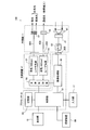
- FIG. 1 is a schematic configuration diagram of an endoscope apparatus using an endoscope light source device for describing an embodiment of the present invention.
- FIG. It is a block block diagram of the endoscope apparatus shown in FIG. It is a graph which shows the emission spectrum of the light after the wavelength conversion of the laser beam from a violet laser light source, the blue laser beam from a blue laser light source, and a blue laser beam is carried out with the fluorescent substance.
- It is a detailed block diagram of an image processing unit. It is explanatory drawing which represented typically the blood vessel of the mucous membrane surface layer of a biological tissue. It is explanatory drawing which shows the schematic example of a display of the observation image by an endoscope apparatus. It is an enlarged observation image by white light inside the lips observed by the endoscope apparatus.
- FIG. 1 is a schematic configuration diagram of an endoscope apparatus using an endoscope light source device for explaining an embodiment of the present invention
- FIG. 2 is a block configuration diagram of the endoscope apparatus shown in FIG.
- An endoscope apparatus 100 illustrated in FIG. 1 includes an endoscope 11 and a control device 13 to which the endoscope 11 is connected.
- the control device 13 is connected to a display unit 15 that displays image information and an input unit 17 that receives an input operation.
- the endoscope 11 is an electronic endoscope having an illumination optical system that emits illumination light from the distal end of the endoscope insertion portion 19 and an imaging optical system that includes an imaging element that captures an image of an observation region.
- the endoscope 11 includes an endoscope insertion portion 19 to be inserted into a subject, a bending operation of the distal end of the endoscope insertion portion 19, suction from the distal end of the endoscope insertion portion 19, air supply / water supply, etc.
- An operation unit 23 that performs the above-described operation
- a connector 25 that detachably connects the endoscope 11 to the control device 13, and a universal cord unit 27 that connects the operation unit 23 and the connector 25.
- the endoscope 11 is provided with various channels such as a forceps channel for inserting a tissue collection treatment tool and the like, a channel for air supply / water supply, and the like.
- the endoscope insertion portion 19 includes a flexible soft portion 31, a bending portion 33, and a tip portion (hereinafter also referred to as an endoscope tip portion) 35.
- the endoscope distal end portion 35 has irradiation ports 37A and 37B for irradiating light to the observation region, a CCD (charge-coupled device) image sensor or a CMOS (Complementary Metal-Oxide Semiconductor) that acquires image information of the observation region.
- An image sensor 21 such as an image sensor is disposed.
- C cyan
- M magenta
- Y yellow
- C C
- M magenta
- Y yellow
- C, M , Y, G sensitivity may be used.
- An imaging member 39 such as an objective lens is attached to the image sensor 21.
- the bending portion 33 is provided between the flexible portion 31 and the distal end portion 35 and can be bent by a wire operation from the operation portion 23, an operation operation of an actuator, or the like.
- the bending portion 33 can be bent in an arbitrary direction and an arbitrary angle according to a part of the subject in which the endoscope 11 is used, and the irradiation ports 37A and 37B of the endoscope distal end portion 35 and the imaging element 21. Can be directed to a desired observation site. Although illustration is omitted, cover glasses and lenses are arranged at the irradiation ports 37A and 37B of the endoscope insertion portion 19.
- the control device 13 includes a light source device 41 that generates illumination light to be supplied to the irradiation ports 37A and 37B of the endoscope distal end portion 35, and a processor 43 that performs image processing on an image signal from the imaging device 21, and the display described above.
- the unit 15 and the input unit 17 are connected.
- the processor 43 performs image processing on the imaging signal transmitted from the endoscope 11 based on an instruction from the operation unit 23 or the input unit 17 of the endoscope 11, and generates a display image on the display unit 15. Supply.
- optical fibers 45 A and 45 B for introducing illumination light from the light source device 41 and a scope cable 47 connecting the image sensor 21 and the processor 43 are inserted.
- various signal lines from the operation unit 23 and tubes such as an air supply and water supply channel are also connected to the control device 13 and the like through the universal cord unit 27 via the connector 25.
- the connector 25 on the endoscope 11 side is detachably connected to connector portions 26A and 26B provided in the light source device 41 and the processor 43, respectively, as shown in FIG.
- the light source device 41 includes a blue laser light source (first light source) 51 having a central wavelength of 445 nm and a violet laser light source (second light source) 53 having a central wavelength of 405 nm as light emission sources. .
- Light emission from the semiconductor light emitting elements of these light sources 51 and 53 is individually controlled by the light source control unit 55, and the light quantity ratio between the emitted light of the blue laser light source 51 and the emitted light of the violet laser light source 53 is changed. It is free.
- the blue laser light source 51 as the first light source and the violet laser light source 53 as the second light source can use a broad area type InGaN laser diode, and use an InGaNAs laser diode or a GaNAs laser diode. You can also.
- a light-emitting body such as a light-emitting diode may be used as the light source.
- Laser light emitted from each of the light sources 51 and 53 is input to an optical fiber by a condensing lens (not shown), and light is transmitted through the connector portion 26A and the connector 25 on the endoscope 11 side (see FIG. 1).
- the fibers 45A and 45B are propagated to the endoscope distal end portion 35 (see FIG. 1) of the endoscope 11, respectively.
- the laser light from the blue laser light source 51 is irradiated to the phosphor 57 which is a wavelength conversion member disposed at the endoscope distal end portion 35, and the laser light from the violet laser light source 53 is irradiated with the light deflection / diffusion member 59. Is irradiated.
- the optical fibers 45A and 45B are multimode fibers.
- a thin cable having a core diameter of 105 ⁇ m, a cladding diameter of 125 ⁇ m, and a diameter including a protective layer that is an outer cover of ⁇ 0.3 to 0.5 mm can be used.
- the blue laser light source 51 the phosphor 57, and the optical fiber 45A connecting them, for example, “Micro White” (trade name) manufactured by Nichia Corporation can be used.
- the light deflection / diffusion member 59 may be any material that transmits the laser light from the violet laser light source 53.
- a light-transmitting resin material or glass is used.
- the light deflection / diffusion member 59 has a configuration in which a light diffusion layer in which fine irregularities or particles (fillers, etc.) having different refractive indexes are mixed on a resin material or glass surface, or a semi-transparent material. It is good also as a structure using. Thereby, the transmitted light emitted from the light deflection / diffusion member 59 becomes illumination light with a narrow band wavelength in which the amount of light is made uniform within a predetermined irradiation region.
- the phosphor 57 and the light deflecting / diffusing member 59 are caused by speckle generated by the coherence of the laser light, noise superposition, which is an obstacle to imaging, flickering when performing moving image display, etc. Can be prevented.
- the phosphor 57 takes into account the difference in refractive index between the phosphor constituting the phosphor and the fixing / solidifying resin serving as the filler, and the particle size of the phosphor itself and the filler is set to the light in the infrared region.
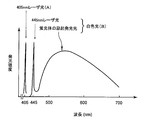
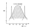
- FIG. 3 is a graph showing the emission spectrum of the laser light from the violet laser light source 53, the blue laser light from the blue laser light source 51, and the light after the blue laser light has been wavelength-converted by the phosphor 57.
- the violet laser light from the violet laser light source 53 is represented by an emission line (profile A) having a center wavelength of 405 nm.
- the blue laser light from the blue laser light source 51 is represented by a bright line having a central wavelength of 445 nm, and the excitation light emitted from the phosphor 57 by the blue laser light has a spectral intensity that increases the emission intensity in a wavelength band of approximately 450 nm to 700 nm.
- Intensity distribution profile B).
- the white light described above is formed by the profile B of the excitation emission light and the blue laser light.
- the white light referred to in this specification is not limited to one that strictly includes all wavelength components of visible light, and may be any light that includes light in a specific wavelength band such as R, G, and B, for example.
- a specific wavelength band such as R, G, and B
- light including a wavelength component from green to red, light including a wavelength component from blue to green, and the like are included in a broad sense.
- the illumination light is generated by relatively increasing / decreasing the light emission intensities of the profile A and the profile B, so that the illumination light having different characteristics according to the mixing ratio of the profiles A and B is obtained. be able to.
- the illumination light formed by the blue laser light source 51, the phosphor 57, and the violet laser light source 53 as described above is emitted from the distal end portion of the endoscope 11 toward the observation region of the subject. Then, the state of the observation region irradiated with the illumination light is imaged on the imaging element 21 by the imaging lens 61 and imaged.
- the image signal output from the image sensor 21 after imaging is converted into a digital signal by the A / D converter 63 and input to the image processing unit 65 of the processor 43.
- the image processing unit 65 converts the input image signal into image data, performs appropriate image processing, and generates desired output image information. Then, the obtained image information is displayed on the display unit 15 as an endoscopic observation image through the control unit 67. Moreover, it records on the recording device 69 which consists of a memory and a storage apparatus as needed.
- the recording device 69 may be built in the processor 43 or may be connected to the processor 43 via a network.
- the information of the endoscopic observation image recorded in the recording device 69 is recorded together with the information on the light amount ratio at the time of imaging.
- the range of utilization of endoscopic observation images can be expanded. In particular, if the spectral reflectance estimation is performed by artificially increasing the number of bands (R, G, B) based on information on a plurality of light amounts with different spectral ratios, it is possible to separate finer color differences. .
- Fig. 4 shows a detailed block diagram of the image processing unit.
- the image signal from the image sensor 21 input to the image processing unit 65 is first input to the luminance calculation unit 65a.
- the luminance calculation unit 65a obtains luminance information such as the maximum luminance, the minimum luminance, and the screen average luminance of the image signal, and normalizes the luminance. If the luminance of the image signal is too low or too high, a correction signal is output to the light source control unit 55 to increase or decrease the light emission amounts of the light sources 51 and 53 so that the image signal has a desired luminance level. .
- the color matching unit 65b adjusts the normalized image data so that the color tone of the image becomes a desired color tone. For example, when the image signal is composed of R, G, and B color signals, the intensity balance of the R, G, and B color signals is adjusted.
- the light source control unit 55 controls the light emission amounts of the blue laser light source 51 and the violet laser light source 53, respectively, and the light amounts of the emitted light from the blue laser light source 51 and the emitted light from the violet laser light source 53.
- the ratio can be arbitrarily changed. Therefore, since the color of the illumination light and the total illuminance may change according to the set light amount ratio, the luminance calculation unit 65a and the color matching unit 65b correct the image signal according to the set light amount ratio.
- the color tone and brightness of the observation image are maintained at a predetermined constant level.
- the image calculation unit 65c performs a predetermined or requested image calculation
- the display image generation unit 65d generates output image information and outputs it to the control unit 67.
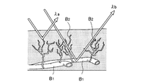
- FIG. 5 is an explanatory view schematically showing blood vessels on the mucous membrane surface layer of a living tissue. It is reported that the mucosal surface layer of the living tissue is formed between the blood vessel B1 in the deep mucosa and the capillary blood vessel B2 such as a resinous vascular network to the mucosal surface layer, and the lesion of the living tissue appears in the fine structure such as the capillary blood vessel B2. Has been.
- an endoscopic device is used to observe a capillary blood vessel on the surface of the mucosa with a specific narrow-band wavelength light to observe the image, thereby early detection of a minute lesion and diagnosis of a lesion area have been attempted.
- a light source having a central wavelength of 360 to 800 nm, preferably 365 to 515 nm, and more preferably a central wavelength of 400 nm to 470 nm is used for blood vessel observation on the surface of a living tissue.
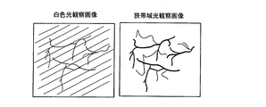
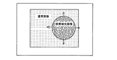
- FIG. 6 which shows a schematic display example of the observation image by the endoscope apparatus
- the observation image when the illumination light is white light can obtain a relatively deep mucosal blood vessel image, but the mucosal surface layer.
- the fine capillaries appear blurry.
- fine capillaries on the surface of the mucosa can be seen clearly.
- the light source control unit 55 (see FIG. 2) of the endoscope apparatus 100 can change the light quantity ratio of the emitted light by the blue laser light source 51 having the center wavelength of 445 nm and the violet laser light source 53 having the center wavelength of 405 nm. ing.
- the change in the light quantity ratio can be performed, for example, by operating a switch 89 provided in the operation unit 23 of the endoscope 11 shown in FIG. That is, when there are many blue laser light components by the blue laser light source 51, it becomes illumination light with many white light components by this blue laser light and the excitation light emission by the fluorescent substance 57, and is like the white light observation image of FIG. An observation image is obtained. However, since blue laser light, which is narrow-band light, is mixed in the illumination light, an observation image in which the surface capillary is image-enhanced is obtained.
- the violet laser light component by the violet laser light source 53 is large, an observation image such as the narrow-band light observation image in FIG. 6 is obtained. Then, by increasing / decreasing the light quantity ratio of the emitted light of the blue laser light source 51 and the purple laser light source 53, that is, by increasing / decreasing the ratio of the purple laser light component to the total illumination light component, Observation with continuous highlighting can be performed.
- the violet laser light component increases, the fine capillaries contained in the thin depth region of the mucosal surface layer are clearly displayed in the observation image, and as the violet laser light component decreases, the mucosal surface layer moves toward the deep layer.
- Blood vessel information included in a wide depth region is displayed.
- the blood vessel distribution in the depth direction can be displayed from the mucous membrane surface layer, and the blood vessel information in the depth direction of the observation site can be extracted as continuous information corresponding to each depth range.
- blood vessel information obtained by blue laser light and blood vessel information on the surface layer obtained by purple laser light are extracted together, and both can be compared by image display of these information. It is possible to observe the blood vessel information including the blood vessels on the surface layer, which has not been able to be performed, with improved visibility.
- the heat generation amount is increasing with the increase in power consumption such as the recent increase in the number of pixels and the increase in the frame speed.
- the light that can be emitted from the tip 35 is also limited.
- by changing the light quantity ratio of each light source and suppressing the total light quantity of the illumination light increasing the necessary light emission depends on, for example, only image processing, resulting in only a noisy image. Problems such as inability to obtain can be solved.
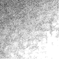
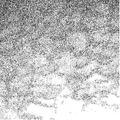
- FIGS. 7A, 7B, and 7C show enlarged images of the inside of the lips observed under the same image processing conditions with the same light amount by the endoscope apparatus 100.
- FIG. 7a an observation image of a blue laser beam having a central wavelength of 445 nm and a white illumination light composed of excitation light emitted from a phosphor, a purple laser beam having a central wavelength of 405 nm, and a blue laser beam having a central wavelength of 445 nm.
- illumination light includes excitation light emitted from a phosphor that uses blue laser light having a central wavelength of 445 nm as excitation light.
- the observation depth from the surface layer becomes shallower in the order of a ⁇ b ⁇ c depending on the wavelength of the illumination light, and the amount of projection of fine capillaries increases.
- the ratio of the violet laser light in the illumination light increases, an image in which the capillaries on the surface layer are more emphasized is obtained, and the capillaries and fine patterns on the mucosa surface layer are observed more clearly with increased contrast.
- the light quantity ratio of blue laser light and violet laser light can be freely changed in a stepless manner, so that the three-dimensional blood vessel structure in the surface layer of the mucosa can be inferred from changes in the observed image when the light quantity ratio is continuously changed. It is easy to selectively and clearly project a desired observation target.
- the amount of light in the violet region alone can be increased or decreased separately from the light in the blue region, such as in conventional halogen lamps, xenon lamps and color filters. It is difficult to realize with wavelength limiting means. If the emission spectrum is narrowed using wavelength limiting means in the optical path, the original halogen lamp or xenon lamp itself has a small amount of light, and the amount of light in the purple region is further insufficient. In addition, if the half-value width of the emission spectrum is increased in order to increase the amount of light in the purple region, the illumination light cannot be narrowed and image enhancement of a desired blood vessel becomes insufficient.
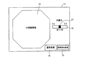
- FIG. 8 shows an example of the display screen 71 of the display unit 15 that displays an observation image obtained by the endoscope apparatus 100.
- the display screen 71 includes an endoscope image area 73 for displaying an observation image obtained by the endoscope apparatus, a normal image switching button 75 for displaying an observation image obtained by normal white light illumination in the endoscope image area 73, a purple laser.
- a narrow-band light image switching button 77 for displaying an observation image by light narrow-band illumination light is provided, and an adjustment bar 79 and a knob 81 for adjusting the light quantity ratio are further provided. Then, based on an instruction from the input unit 17 such as a mouse or a keyboard, the knob 81 is slid within the adjustment bar 79 to adjust the light amount ratio so that a desired observation image is obtained.
- the controller 67 determines the light amount ratio according to the position of the knob 81 of the adjustment bar 79, and drives the light sources 51 and 53 so that the light amounts emitted from the light sources 51 and 53 corresponding to the light amount ratio are obtained.
- the relationship between the light amount ratio and the emitted light amount of each of the light sources 51 and 53 is stored in the storage unit 83 (see FIG. 2) as a light amount ratio correspondence table, and the control unit 67 corresponds to the light amount ratio of the storage unit 83.
- the amount of light emitted from each of the light sources 51 and 53 is obtained with reference to the table.
- the control unit 67 is stored in advance based on the light amount ratio set on the display screen 71.
- the emitted light quantity of each light source 51, 53 is determined with reference to the light quantity ratio correspondence table. Thereby, the light quantity of each light source 51 and 53 can be set so that it may become a desired light quantity ratio by simple operation, without the operator of an endoscope setting directly.
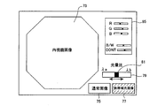
- the change of the light amount ratio may be set by using the setting unit 85 for various adjustments of the intensity balance, luminance, and contrast of the R, G, and B color components of the image signal. Or you may use together with adjustment of the knob 81 for light quantity ratio change.
- a desired observation target can be displayed with image emphasis arbitrarily such as by expressing it in a pseudo color, and the degree of freedom in changing the display image is improved, thereby making it easier to diagnose.
- the light source control unit 55 illustrated in FIG. 2 controls the amount of light emitted from each of the light sources 51 and 53 based on an instruction from the input unit 17.
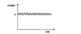
- Each of the light sources 51 and 53 has a relationship R1 between the applied current and the light emission amount as shown in FIG. 10, and a desired light emission amount is obtained by controlling the applied current to each of the light sources 51 and 53.
- the applied current is Ib
- the light emission amount Lb based on the relation R1 is ensured
- the difference ⁇ L between the light emission amounts Lb and La as a fine adjustment allowance is pulse-modulated to the applied current. Obtained by superimposing the pulse currents.
- the light emission amount La is obtained by a pulse current having the applied current Ib as a bias.
- bias current control and pulse modulation control a wide dynamic range of light emission amount that can be set can be secured.
- various drive waveforms can be used for the pulse modulation control.
- a pulse waveform that repeatedly turns on and off in synchronization with the light accumulation time for one frame of the image of the image sensor as shown in FIG. 12A it is less susceptible to the influence of the dark current of the CCD and CMOS image sensors. The sharpness of the image increases.
- a pulse waveform having a period sufficiently fast with respect to the light accumulation time as shown in FIG. 12B is used, the occurrence of flicker related to image display can be reduced, and an image due to laser speckles can be reduced. Noise can also be reduced.
- the ON period of the pulse waveform of FIG. 12A is a pulse waveform with a fast cycle of FIG. The above effects other than flicker reduction can be enjoyed.
- the maximum driving power of the light source device 41 including the light sources 51 and 53 is suppressed. And the burden on the living body as the subject can be reduced.
- the captured image by the illumination light of each light source 51 and 53 can also be acquired separately, In that case, the calculation between images of the acquired image is also attained, and the freedom degree of image processing improves.
- FIG. 15 shows the display unit 15 when the endoscope operator moves the endoscope insertion portion within the subject, performs observation with narrow band light at a desired observation position, and moves to the next observation position.
- the appearance of the display image (see FIGS. 1 and 2) is schematically shown.
- Switching from a normal display image by white light observation to a display image by narrow-band light observation and switching in the opposite direction are performed by one frame of a captured image (R, G, B three-color full color image) of the image sensor 21. Switching is possible in units. For this reason, even when observing while moving the endoscope insertion portion, an image without color misregistration can be displayed in real time without causing the operator to feel uncomfortable. That is, it is possible to provide a good observation image that reliably follows the quick movement of the endoscope, and to improve the operability of the endoscope apparatus.
- a normal image at the time of white light observation and a narrow band light image at the time of narrow band light observation can be freely arranged.
- a normal image and a narrowband light image in which specific information is emphasized by arranging a normal image and a narrowband light image in separate areas in the same screen and displaying them simultaneously. It becomes easy to compare and observe the optical image.
- the blue laser light source 51 is turned on to capture an image for a normal image using white light, and in the next frame, the blue laser light source 51 and the purple laser light source 53 are turned on at the same time to capture an image. Repeatedly, the obtained normal image and narrowband light image are displayed in the respective display areas.
- FIG. 17 shows a display screen of a so-called P (in P (Picture in Picture) function, in which a narrow-band light image in a desired range is superimposed on a normal image and displayed simultaneously.
- the display range of the narrowband light image can be set to an arbitrary position and an arbitrary size in the normal image according to an instruction from the input unit 17 (see FIGS. 1 and 2).
- An image at the same position as the display position of the subject in the normal image is displayed in the display range of the narrow-band light image. Thereby, comparative observation at the same position becomes easier.
- the above display pattern is merely an example, and a display form in which a normal image is embedded in a narrow-band light image may be used, and it is needless to say that any other combined display can be performed.
- the light source control unit 55 can arbitrarily set the light quantity ratio of the emitted light from the blue laser light source 51 and the violet laser light source 53 shown in FIG.
- a case where a plurality of types of light quantity ratios are registered in advance and one of the light quantity ratios is designated from the input unit 17 will be described.
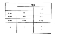
- the preference of the light quantity ratio of blue laser light and violet laser light may differ for each operator of the endoscope.
- the operator A feels favorable for an observation image in which the light quantity ratio between the violet laser light ⁇ a and the blue laser light ⁇ b is 60:40, and the operator B feels a light quantity ratio of 75:25.
- the light quantity ratio information that associates the surgeon name as key information with the preferred light quantity ratio of the surgeon is stored in the storage unit 83 (see FIG. 2) or the like as a light quantity ratio table. Register in advance.
- control unit 67 automatically sets a desired light amount ratio with reference to the light amount ratio table of the storage unit 83. Thereby, it can set to the light quantity ratio according to the operator's preference of an endoscope.
- optical characteristics may vary depending on the individual of the endoscope
- individual identification information for identifying the individual of the endoscope may be used as key information instead of the operator name used as the key information.
- information on the light quantity ratio corresponding to the number, model name, etc. given to each individual endoscope is registered in advance as a light quantity ratio table. Thereby, the optimal light quantity ratio can be set according to the type and characteristics of each endoscope.
- a plurality of preset light quantity ratios are displayed as “selection buttons” 87 of GUI (Graphical User Interface), and an operator or assistant can display the display unit. 15 (see FIGS. 1 and 2), the user can select freely by operating the input unit 17.
- the display unit 15 is a touch panel, the switch operation can be performed more intuitively and quickly by directly touching the selection button 87 on the display unit 15 that the operator is gazing at.
- the operator can compare the observation images that change due to the change in the light amount ratio without taking his eyes off, and can recognize a subtle image change more reliably.
- the switching of the light amount ratio is not limited to the display pattern on the display unit 15, and the switch 89 provided on the operation unit 23 of the endoscope 11 shown in FIG. 1 may be operated as a changeover switch.
- the switch 89 in the operation unit 23 the light quantity ratio can be changed quickly and easily without the operator removing his / her hand from the endoscope 11, and the operability of the endoscope is improved.
- switches such as a toggle switch, a push switch, a slide switch, and a rotary switch can be used.
- Different light quantity ratios preset in advance are sequentially set. For example, normal light observation with white light by the blue laser light source 51 and phosphor 57 in FIG. 2 and narrow band light observations A and B in which narrow band light from a violet laser light source 53 is superimposed on white light at a predetermined ratio. , C,..., Or observation light modes with a plurality of light intensity ratios such as narrow-band light observation using only narrow-band light.
- the switch 89 for switching the light amount ratio is not limited to switching the preset light amount ratio, and may be a volume switch or a slide switch for continuously changing the light amount ratio. In this case, it becomes easy to optimally adjust the light amount ratio according to the observation target. Further, by continuously changing the light amount ratio by the switch operation, it is possible to observe a continuous change in the observation image, and it is possible to more accurately grasp the blood vessel structure.
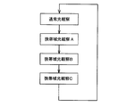
- Image signals R, G, and B are input to the image processing unit 65 shown in FIG. 4, and the luminance calculation unit 65a normalizes the luminance of the image signals R, G, and B, and Rnorm, Gnorm, and Bnorm. Converted to image data.
- the normalized image data Rnorm, Gnorm, and Bnorm are corrected to the color tone according to the light amount ratio by the color matching unit 65b. That is, the color matching unit 65b obtains the image data Radj, Gadj, and Badj after color tone correction by calculation as shown in the equation (1).
- k R , k G , and k B are color conversion coefficients of the respective colors, and are determined according to the light amount ratio set at the time of imaging.
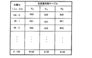
- FIG. 21 shows a color conversion coefficient table in which the color conversion coefficients of the respective colors corresponding to the light quantity ratio are determined.
- the color conversion coefficients k R , k G , and k B are set as R00 to R100, G00 to G100, and B00 to B100 corresponding to each light quantity ratio, and are stored in the storage unit 83 (see FIG. 2). Yes.
- a violet laser beam (and a blue laser beam), that is, an illumination light having a short wavelength band particularly suitable for blood vessel observation is used to image a fine blood vessel on the surface of a living tissue. It can be observed with emphasis, and observation of the fine structure of the blood vessel becomes easy. And since the light quantity ratio of the emitted light of the violet laser beam and the blue laser beam (white light) can be continuously changed, it is possible to easily observe the blood vessel structure that changes in the depth direction from the surface of the living tissue. The blood vessel structure in the surface layer can be clearly understood. Therefore, when observing a living tissue with white light or special light, desired tissue information of the living tissue can be acquired in a clearer state suitable for diagnosis, and endoscopic diagnosis can be performed smoothly.
- the endoscope apparatus 100 is configured as a so-called magnifying endoscope including an imaging optical system capable of magnifying and observing an observation region, the microvessel and the fine pattern of the mucous membrane on the surface of the living tissue Therefore, it becomes possible to perform more advanced endoscopic diagnosis.
- enlarged observations can confirm the presence of abnormalities such as irregularities such as caliber, uneven shape, dilation, meandering, loss of mucosal fine pattern, irregularities such as irregular micronization, etc.
- Can provide useful information such as
- FIG. 22 shows absorption spectra of hemoglobin Hb having a low oxygen concentration and oxygen-saturated hemoglobin HbO 2 having a wavelength of 450 nm to 700 nm.
- the wavelength ⁇ 1 at the isosbestic point where the absorption of hemoglobin Hb and oxyhemoglobin HbO 2 are equal, and the wavelength ⁇ 2 where the absorptions of both are different are selected, and the observation image by the illumination light of wavelength ⁇ 1 Brightness Ab1 and brightness Ab2 of the observation image by the illumination light of wavelength ⁇ 2.
- the ratio of the luminance Ab1 and Ab2 in these images serves as an index representing the oxygen concentration in the blood, and changes in the metabolic state of the living tissue can be monitored.
- a cancer region has a low oxygen concentration, and the oxygen concentration is useful information for endoscopic diagnosis.
- the endoscope apparatus 200 includes a plurality of light sources in the light source apparatus 41 as shown in FIG. Is added.
- blue-green laser light from a blue-green laser light source 91 having a center wavelength of 515 nm is used as illumination light at an isosbestic point
- red laser from a red laser light source 93 having a center wavelength of 630 nm is used as illumination light having a different absorption.
- the purple laser light source 53 can be omitted.
- symbol in a figure attaches
- the optical fibers 45A, 45B, 45C, and 45D configured as described above are preferably selected and used in accordance with the wavelengths used.
- the core of the optical fiber has a wavelength dependency in which the transmission loss changes depending on whether the hydroxyl group (OH ⁇ ) concentration is high or low, and the specific wavelength in the infrared region has an absorptivity different from the wavelength in the visible region. Therefore, when the wavelength of the light source is 650 nm or less, a high-hydroxyl concentration core optical fiber is used, and when it exceeds 650 nm, a low-hydroxyl concentration core optical fiber is used.
- an observation region is imaged using the blue-green laser light from the blue-green laser light source 91 as illumination light, and then the observation region using the red laser light from the red laser light source 93 as illumination light. Image.
- the emitted light amounts of the light sources 91 and 93 are adjusted so that the average luminance value of the observation image data is constant.
- the oxygen concentration index Oindx is obtained for each pixel by the equation (2) from the luminances Ab1 and Ab2 of the obtained observation images.
- Oindx k ⁇ (Ab2 / Ab1) (2) However, k is a coefficient.
- the blue-green laser light source 91 and the red laser light source 93 can individually change the amount of emitted light by the light source control unit 55, and the contents of observation objects and procedures
- the light quantity ratio of each outgoing light is adjusted according to the above.
- Each of the laser light sources 91 and 93 may emit light within one frame of the imaging signal, and the light amount ratio may be adjusted as appropriate.
- Blue-green laser light is suitable for observing fine blood vessels and redness of living tissue
- red laser light is suitable for observing deep blood vessels in living tissue. Therefore, by changing the light amount ratio of the emitted light of each laser beam, information from different regions in the depth direction and information from different objects can be displayed with image enhancement as described above.
- the light quantity ratio of blue-green laser light to white light, the light quantity ratio of red laser light to white light, or the light quantity ratio of blue-green laser light and red laser light are arbitrarily and continuously changed.
- the visibility of a desired observation target can be enhanced and displayed.
- the endoscope can be quickly removed without removing it from the subject. Observation with appropriate illumination light according to the observation object becomes possible.
- it can also be set as the structure which uses white light sources, such as a halogen lamp, instead of producing
- FIG. 24 shows a configuration example of the light source device 41 and the endoscope 11.
- the endoscope apparatus 300 includes a violet laser light source having a central wavelength of 405 nm in the middle of an optical path until blue laser light from a blue laser light source 51 having a central wavelength of 445 nm is introduced into an optical fiber 45A through a condenser lens (not shown).
- a dichroic prism 95 is provided as optical coupling means for merging the violet laser beams from 53.
- wavelength conversion by the phosphor 97 there is a wavelength conversion loss (Stokes loss) such as heat generated in principle. Therefore, it is known that selecting an excitation wavelength having a long emission wavelength has higher luminous efficiency of the phosphor and is advantageous in suppressing heat generation of the phosphor. Therefore, in this configuration example, white light is generated by the laser light on the long wavelength side to increase the light emission efficiency.
- the light source device 41 to the phosphor 97 are guided by the single optical fiber 45A, and the illumination light Can be accommodated in one place of the phosphor 97, so that space efficiency can be improved and the diameter of the endoscope insertion portion can be reduced.
- the phosphor 97 in this configuration example for example, as described in JP-A-2006-2115, lead (Pb) as an additive element and digallium calcium tetrasulfide (CaGa 2 ) are included.
- Crystalline solid fluorescent material based on S 4 ), or crystalline solid fluorescent material based on 2 gallium calcium tetrasulfide (CaGa 2 S 4 ) containing lead (Pb) and cerium (Ce) as additive elements Material can be used. According to this phosphor material, it is possible to obtain fluorescence of approximately 460 nm to approximately 660 nm that covers almost the entire visible range, and the color rendering property during white light illumination is improved.
- LiTbW 2 O 8 which is a green phosphor (Yoshitoshi Oda, “About phosphor for white LED”, IEICE Technical Report ED2005-28, CFM2005-20, SDM2005-28, pp .69-74 (2005-05), etc.), ⁇ -sialon (Eu) blue phosphor (Naoto Hirosaki, Hoei Army, Ken Sakuma, “Sialon-based phosphor and white color using it” Development of LED ", Journal of Applied Physics, Vol. 74, No. 11, pp.1449-1452 (2005), or Akira Yamamoto, Tokyo University of Technology, Department of Pionics, Vol. 76, No.
- Beta sialon is a crystal having a composition of Si 6-z Al 2 O 2 N 8-z (z is a solid solution amount) in which aluminum and an acid are dissolved in ⁇ -type silicon nitride crystal.
- the phosphor 97 may be a mixture of these LiTbW 2 O 8 , beta sialon, and CaAlSiN 3 , or may have a configuration in which these phosphors are stacked in layers.
- Each phosphor illustrated above is excited by the blue laser light from the blue laser light source 51 and does not emit light by the violet laser light from the other violet laser light source 53, that is, in the main excitation wavelength band unique to the phosphor.
- the emission wavelength of other light sources should not be included.
- white light is generated by the blue laser light and the excitation light emitted from the phosphors 57 and 97.
- the present invention is not limited to this.
- green excitation light is generated by the blue laser light.
- Various light sources and phosphors can be combined to generate white light, such as a configuration using a phosphor and a phosphor that generates red excitation light by violet laser light.
- An endoscope illumination device that obtains illumination light using emitted light from a plurality of light sources, A first light source having a semiconductor light emitting element as a light source; A second light source that uses a semiconductor light emitting element having an emission wavelength different from that of the first light source as a light source; A wavelength conversion member that excites and emits light by light emitted from at least one of the first and second light sources; A light amount ratio changing means for changing a light amount ratio between the light emitted from the first light source and the light emitted from the second light source;
- Endoscopic illumination device comprising: According to this endoscope illumination device, since the light quantity ratio of the emitted light from the first light source and the second light source can be changed, the illumination light having a large amount of emitted light component from the first light source, and the second It is possible to arbitrarily generate illumination light having a large amount of light emitted from the light source and intermediate illumination light. Therefore, illumination light suitable for diagnosis can be provided
- the endoscope illumination device An endoscope illumination device in which an emission wavelength of at least one of the first light source and the second light source is included in a range of 400 nm to 470 nm.
- an endoscope illumination device by using the light of the semiconductor light emitting element having a wavelength of 400 nm to 470 nm, it is possible to observe the blood vessel particularly in the surface layer portion of the living tissue with emphasis.
- the wavelength conversion member is an endoscope that is a phosphor that generates white light by light emitted from the wavelength conversion member by excitation light and light emitted from at least one of the first and second light sources. Lighting equipment.
- white light is generated by the light emission of the wavelength conversion member using the light from the semiconductor light emitting element as the excitation light, so that high intensity white light can be obtained with high luminous efficiency. Further, since the semiconductor light emitting element is used as an excitation light source, the intensity of white light can be easily adjusted, and the change in the color temperature and chromaticity of the white light is small.
- An endoscope illuminating apparatus further comprising at least one third light source having a light emitting source of a semiconductor light emitting element having a light emitting wavelength different from that of the first and second light sources, with a different light emitting wavelength for each light source.
- the endoscope illumination device by further including the third light source having a different emission wavelength, the wavelength band of the illumination light can be expanded, and the degree of freedom in selecting the wavelength of the illumination light is improved. Thereby, illumination light for various image formations, such as a blood vessel emphasis image by purple light and blue light, and a distribution image of oxygen concentration by green light and red light, can be obtained.
- the endoscope illumination device according to any one of (1) to (4), Light that is disposed in the optical path from the first light source to the wavelength conversion member and guides the emitted light from at least the second light source to the wavelength conversion member together with the emitted light from the first light source.
- Endoscopic illumination device including coupling means. According to this endoscope illuminating device, a single optical path is sufficient from the optical coupling means to the wavelength conversion member, and space efficiency is further improved when the endoscope illuminating device is incorporated into the endoscope device. A simple and enhanced configuration can be achieved.
- the endoscope illumination device according to any one of (2) to (5), Among the emission wavelengths of the first light source and the second light source, either one is set on the short wavelength side across the maximum peak wavelength of the absorption wavelength band of hemoglobin, and the other is set on the long wavelength side. Endoscopic lighting device. According to the endoscope illumination device, blood vessel information can be captured with high contrast. Further, by reducing the illumination light component in the vicinity of the maximum absorption wavelength of hemoglobin, it is possible to prevent the observation image from becoming dark due to absorption of blood that has exuded into the tissue surface layer.
- the endoscope illumination device according to any one of (1) to (6), An endoscope illumination apparatus, wherein the light amount ratio changing means changes the light amount of the emitted light from each light source independently.
- the spectral characteristic of illumination light finally formed by each light source light can be adjusted with a high degree of freedom by making the amount of emitted light freely changeable for each light source. .
- the endoscope illumination device according to any one of (1) to (7), It further comprises input means for inputting light quantity ratio information for designating a desired light quantity ratio, The endoscope illumination device, wherein the light amount ratio changing unit determines the emitted light amount of each of the light sources having the desired light amount ratio based on the light amount ratio information input to the input unit.
- the light amount ratio is designated by the light amount ratio information input from the input unit, and the emitted light amount of the light source that satisfies this light amount ratio is determined. That is, the light quantity ratio can be freely changed as specified.
- the endoscope illumination device A storage means for storing a light quantity ratio table in which a plurality of types of light quantity ratios are associated with key information;
- the light quantity ratio information includes the key information,
- the endoscope illumination device wherein the light amount ratio changing unit determines the desired light amount ratio with reference to the light amount ratio table based on key information included in the light amount ratio information input from the input unit.
- a desired light amount ratio is determined with reference to the light amount ratio table based on the key information included in the light amount ratio information. That is, by registering the light amount ratio for each key information in the light amount ratio table in advance, the light amount ratio corresponding to the key information is automatically determined only by specifying the key information.
- the endoscope illumination device according to (9), An endoscope illumination apparatus, wherein the key information is individual identification information of the endoscope apparatus.
- the light amount ratio can be set for each individual in accordance with the type and characteristics of each endoscope device.
- the endoscope illumination device according to any one of (9) to (11), An endoscope illumination apparatus, wherein the input unit is a changeover switch that designates one of a plurality of types of light amount ratios set in the light amount ratio table.
- the input unit is a changeover switch that designates one of a plurality of types of light amount ratios set in the light amount ratio table.
- a desired light amount ratio can be arbitrarily designated from among a plurality of types of light amount ratios by operating the changeover switch, and the light amount ratio can be switched quickly and easily.
- Illumination means for emitting illumination light from the endoscope illumination device according to any one of (1) to (12) from a distal end side of an endoscope insertion portion to be inserted into a body cavity;
- An image pickup device for picking up an image of the observation region irradiated with the illumination light is mounted on the endoscope insertion portion, and an image pickup means for outputting an image signal serving as an observation image;
- An endoscopic apparatus comprising: According to this endoscope apparatus, the observation region is irradiated with illumination light in which the light amount ratio of each light emitted from the first light source and the second light source is set to a desired light amount ratio. By taking an image with the imaging element, an observation image corresponding to the light quantity ratio is obtained. That is, illumination light suitable for diagnosis can be irradiated, and desired tissue information of a living tissue can be acquired in a clearer state.
- An endoscope apparatus comprising light source control means for emitting at least the first light source and the second light source within one frame of an image signal of the image sensor.
- an endoscope illumination device an observation image in which light emitted from a plurality of light sources is irradiated onto an observation region is obtained by causing each light source to emit light within one frame of an image signal and capturing an image with an imaging device. Obtainable.
- the endoscope apparatus according to (14), An endoscope apparatus in which the light source control means causes at least the first light source and the second light source to emit light at different timings within one frame of an image signal of the image sensor. According to this endoscope apparatus, it is not necessary to simultaneously emit light from each light source, and the burden on the subject and the power consumption of the apparatus can be suppressed.
- the endoscope apparatus according to any one of (13) to (15), Image processing means for generating an observation image for display based on an image signal output from the image sensor; Display means for displaying information including the display observation image; An endoscopic apparatus comprising: According to this endoscope apparatus, by displaying the information of the image signal from the image sensor on the display means, the observation image can be easily confirmed, and the endoscopic diagnosis can be performed more smoothly.
- the endoscope device according to (16), The display means, first image information imaged under visible light including light emitted from the first light source and excitation light emitted from the wavelength conversion member; An endoscope apparatus that simultaneously displays, in the same screen, second image information captured under illumination light including light emitted from the second light source in addition to the visible light.
- the first image information that is an observation image when visible light having a wide wavelength band is used as illumination light
- the second image information that is an observation image using illumination light including narrow-band light are simultaneously displayed on the same screen of the display means. This makes it easy to compare and observe a normal observation image and an image in which specific information is emphasized.
- the endoscope apparatus according to (16) or (17), The display means, first image information imaged under visible light including light emitted from the first light source and excitation light emitted from the wavelength conversion member; An endoscope apparatus that displays any one piece of image information of second image information picked up under illumination light including light emitted from the second light source in addition to the visible light so as to overlap each other at the same time. According to this endoscope apparatus, a normal observation image and an image in which specific information is emphasized are displayed in a superimposed manner, and it becomes easy to perform comparative observation.
- the endoscope apparatus according to any one of (13) to (18), A recording unit for recording information including an observation image output from the image processing unit; An endoscope apparatus in which the recording unit records the observation image and the light amount ratio in association with each other. According to this endoscope apparatus, since the observation image is recorded in relation to the light amount ratio set when the observation image is captured, the observation image is recorded in accordance with the light amount ratio at the time of imaging. The range of use of the observation image can be expanded by processing the image.
- the endoscope light source device and the endoscope device of the present invention when observing a living tissue using white light or special light in a specific wavelength band, desired tissue information of the living tissue is more suitable for diagnosis. It can be acquired in a clear state.
- the present invention is not limited to the above-described embodiment, and it is intended that the present invention be modified and applied by those skilled in the art based on the description in the specification and well-known technology, and within the scope of seeking protection. included. This application is based on Japanese Patent Application No. 2009-159962 filed on Jul. 6, 2009, the contents of which are incorporated herein by reference.
Landscapes
- Health & Medical Sciences (AREA)
- Life Sciences & Earth Sciences (AREA)
- Surgery (AREA)
- Medical Informatics (AREA)
- Molecular Biology (AREA)
- Veterinary Medicine (AREA)
- Pathology (AREA)
- Public Health (AREA)
- Biophysics (AREA)
- Engineering & Computer Science (AREA)
- Biomedical Technology (AREA)
- Heart & Thoracic Surgery (AREA)
- Physics & Mathematics (AREA)
- General Health & Medical Sciences (AREA)
- Animal Behavior & Ethology (AREA)
- Nuclear Medicine, Radiotherapy & Molecular Imaging (AREA)
- Radiology & Medical Imaging (AREA)
- Optics & Photonics (AREA)
- Endoscopes (AREA)
Abstract
白色光や特殊光による生体組織の観察時に、生体組織の所望の組織情報を、診断に適したより明瞭な状態で取得する。 半導体発光素子を発光源とする第1の光源51と、第1の光源51とは異なる発光波長の半導体発光素子を発光源とする第2の光源53と、第1の光源51、第2の光源53の少なくとも一方からの出射光により励起発光する波長変換部材57と、第1の光源51からの出射光と第2の光源53からの出射光との光量比を変更する光量比変更手段55と、を備えることで、第1の光源51からの出射光と第2の光源53からの出射光を任意に発生させて、生体組織の吸収特性および散乱特性に応じた診断に適した照明光を提供できる。これにより、生体組織の所望の組織情報が、より明瞭な状態で取得可能となる。
Description
本発明は、内視鏡用照明装置及び内視鏡装置に関する。
一般的な内視鏡装置は、光源装置のランプからの光を、被検体内に挿入される内視鏡挿入部に内設されたライトガイドで内視鏡先端部まで導光し、内視鏡先端部の照明窓から出射することで、被検体の観察部位を照明する。通常の生体組織の観察には白色光が用いられるが、近年においては、特定の狭帯域化された波長の光を照射して粘膜組織の状態を強調表示させたり、予め投与した蛍光物質からの自家蛍光を観察する特殊光観察が可能な内視鏡装置が活用されている(特許文献1,2)。この種の内視鏡装置では、生体組織に特殊光を照射することで、例えば粘膜層あるいは粘膜下層に発生する新生血管が観察でき、通常の観察像では得られない粘膜表面の微細構造の描写が可能になる。
上記の特許文献1,2においては、キセノンランプ等の白色光源からの出射光をカラーフィルタにより特定の波長帯域のみ取り出して、特殊光として利用している。なお、白色光源としては、キセノンランプの他にレーザ光源も利用でき、例えば青色レーザ光源と、これを励起光として励起発光する蛍光体との組合せで白色光を発生する発光装置も提案されている(特許文献3)。
しかし、これら特許文献1,2の内視鏡装置においては、白色光源からの光をカラーフィルタによって時分割し、異なる波長帯の光(R,G,B光等)を面順次に発光させる構成となっている。そのため、フルカラーの観察画像を得るには、複数フレーム(R,G,B)の撮像画像を合成する必要があり、観察画像のフレームレートを上げる妨げとなっている。また、カラーフィルタにより光吸収させて照明光を生成しているため、光量の減少は避けられず、観察画像のノイズ成分を増加させる要因となる。フレームレートを落として感度を上げることもできるが、その場合には、画像がブレやすくなる。
一方、特殊光診断においては、生体組織の表層部や深層部にかけての組織情報等が重要な観察対象となる。例えば、消化管癌は早期から腫瘍血管が粘膜の表層部に現れ、腫瘍血管は通常の表層部に見える血管に比べると膨張や蛇行、血管の密度の増加が認められる。そのため、血管の性状を精査することで腫瘍の種類を鑑別できる。しかしながら、上記のカラーフィルタを用いる内視鏡装置では、生体組織の特に表層部の組織情報を観察したい場合等、カラーフィルタの透過波長帯域を特定の狭い帯域内に限定することは難しく、しかも、狭帯域に限定した照明光は十分な光量が得られず、観察画像の画質劣化を招く不利がある。
本発明は、白色光や特殊光による生体組織の観察時に、生体組織の所望の組織情報を、診断に適したより明瞭な状態で取得できる内視鏡用光源装置及び内視鏡装置を提供することを目的とする。
本発明は下記構成からなる。
(1) 複数の光源の出射光を用いて照明光を得る内視鏡用照明装置であって、
半導体発光素子を発光源とする第1の光源と、
前記第1の光源とは異なる発光波長の半導体発光素子を発光源とする第2の光源と、
前記第1、第2の光源の少なくとも一方からの出射光により励起発光する波長変換部材と、
前記第1の光源からの出射光と前記第2の光源からの出射光との光量比を変更する光量比変更手段と、
を備えた内視鏡用照明装置。
(2) 上記内視鏡照明装置からの照明光を内視鏡挿入部の先端から出射する照明光学系と、
前記照明光が照射された被照明領域からの光を受光して画像信号を出力する撮像素子を含む撮像光学系と、
を備えた内視鏡装置。
本発明の内視鏡用光源装置及び内視鏡装置によれば、白色光や特定の波長帯域の特殊光を用いた生体組織の観察時に、生体組織の所望の組織情報を、診断に適したより明瞭な状態で取得できる。
以下、本発明の実施形態について、図面を参照して詳細に説明する。
図1は、本発明の実施形態を説明するための内視鏡用光源装置を用いた内視鏡装置の模式的構成図、図2は図1に示す内視鏡装置のブロック構成図である。
図1に示す内視鏡装置100は、内視鏡11と、この内視鏡11が接続される制御装置13とを有する。制御装置13には、画像情報等を表示する表示部15と、入力操作を受け付ける入力部17が接続されている。内視鏡11は、内視鏡挿入部19の先端から照明光を出射する照明光学系と、被観察領域を撮像する撮像素子を含む撮像光学系とを有する、電子内視鏡である。
図1は、本発明の実施形態を説明するための内視鏡用光源装置を用いた内視鏡装置の模式的構成図、図2は図1に示す内視鏡装置のブロック構成図である。
図1に示す内視鏡装置100は、内視鏡11と、この内視鏡11が接続される制御装置13とを有する。制御装置13には、画像情報等を表示する表示部15と、入力操作を受け付ける入力部17が接続されている。内視鏡11は、内視鏡挿入部19の先端から照明光を出射する照明光学系と、被観察領域を撮像する撮像素子を含む撮像光学系とを有する、電子内視鏡である。
内視鏡11は、被検体内に挿入される内視鏡挿入部19と、内視鏡挿入部19の先端の湾曲操作や内視鏡挿入部19の先端からの吸引、送気・送水等の操作を行う操作部23と、内視鏡11を制御装置13に着脱自在に接続するコネクタ25と、操作部23とコネクタ25とを結ぶユニバーサルコード部27とを備える。なお、図示はしないが、内視鏡11の内部には、組織採取用処置具等を挿入する鉗子チャンネルや、送気・送水用のチャンネル等、各種のチャンネルが設けられる。
内視鏡挿入部19は、可撓性を持つ軟性部31と、湾曲部33と、先端部(以降、内視鏡先端部とも呼称する)35から構成される。内視鏡先端部35には、被観察領域へ光を照射する照射口37A,37Bと、被観察領域の画像情報を取得するCCD(charge coupled device)イメージセンサやCMOS(Complementary Metal-Oxide Semiconductor)イメージセンサ等の撮像素子21が配置されている。撮像素子21としては、R(赤),G(緑),B(青)の感度を有する原色系撮像素子の他、C(シアン),M(マゼンタ),Y(イエロ)、又はC,M,Y,Gの感度を有する補色系撮像素子であってもよい。なお、撮像素子21には対物レンズ等の結像部材39が取り付けられている。
湾曲部33は、軟性部31と先端部35との間に設けられ、操作部23からのワイヤ操作やアクチュエータの作動操作等により湾曲自在にされている。この湾曲部33は、内視鏡11が使用される被検体の部位等に応じて、任意の方向、任意の角度に湾曲でき、内視鏡先端部35の照射口37A,37B及び撮像素子21の観察方向を、所望の観察部位に向けることができる。また、図示は省略するが、内視鏡挿入部19の照射口37A,37Bには、カバーガラスやレンズが配置される。
制御装置13は、内視鏡先端部35の照射口37A,37Bに供給する照明光を発生する光源装置41、撮像素子21からの画像信号を画像処理するプロセッサ43を備えており、前述の表示部15と入力部17が接続されている。プロセッサ43は、内視鏡11の操作部23や入力部17からの指示に基づいて、内視鏡11から伝送されてくる撮像信号を画像処理し、表示部15へ表示用画像を生成して供給する。
内視鏡11の内部には、光源装置41から照明光を導入するための光ファイバ45A,45Bと、撮像素子21とプロセッサ43を結ぶスコープケーブル47が挿通されている。また、図示はしないが、操作部23からの各種信号線及び送気、送水チャンネル等のチューブ類もユニバーサルコード部27を通じてコネクタ25を介し、制御装置13等に接続されている。この内視鏡11側のコネクタ25は、図2に示すように、光源装置41とプロセッサ43のそれぞれに設けられたコネクタ部26A,26Bに着脱自在に接続される。
光源装置41は、図2に示すように、中心波長445nmの青色レーザ光源(第1の光源)51と、中心波長405nmの紫色レーザ光源(第2の光源)53とを発光源として備えている。これらの各光源51,53の半導体発光素子からの発光は、光源制御部55により個別に制御されており、青色レーザ光源51の出射光と、紫色レーザ光源53の出射光との光量比は変更自在になっている。
第1の光源である青色レーザ光源51、及び第2の光源である紫色レーザ光源53は、ブロードエリア型のInGaN系レーザダイオードが利用可能でき、また、InGaNAs系レーザダイオードやGaNAs系レーザダイオードを用いることもできる。また、上記光源として、発光ダイオード等の発光体を用いた構成としてもよい。
これら各光源51,53から出射されるレーザ光は、集光レンズ(図示略)により光ファイバに入力され、コネクタ部26A及び内視鏡11側のコネクタ25(図1参照)を介して、光ファイバ45A,45Bによって、それぞれ内視鏡11の内視鏡先端部35(図1参照)まで伝搬される。そして、青色レーザ光源51からのレーザ光は、内視鏡先端部35に配置された波長変換部材である蛍光体57に照射され、紫色レーザ光源53からのレーザ光は、光偏向・拡散部材59に照射される。
光ファイバ45A,45Bは、マルチモードファイバであり、一例として、コア径105μm、クラッド径125μm、外皮となる保護層を含めた径がφ0.3~0.5mmの細径なケーブルを使用できる。
蛍光体57は、青色レーザ光源51からの青色レーザ光の一部を吸収して緑色~黄色に励起発光する複数種の蛍光体(例えばYAG系蛍光体、あるいはBAM(BaMgAl10O17)等を含む蛍光体等)を含んで構成される。これにより、青色レーザ光源51からの青色レーザ光を励起光とする緑色~黄色の励起光と、蛍光体57により吸収されず透過した青色レーザ光とが合わされて、白色(疑似白色)の照明光となる。本構成例のように、半導体発光素子を励起光源として用いれば、高い発光効率で高強度の白色光が得られ、更に、白色光の強度を容易に調整できる。しかも、白色光の色温度、色度の変化は少なくなる。
なお、青色レーザ光源51、蛍光体57、及びこれらを接続する光ファイバ45Aは、例えば、日亜化学工業社製の「マイクロホワイト」(商品名)を用いることができる。
また、光偏向・拡散部材59は、紫色レーザ光源53からのレーザ光を透過させる材料であればよく、例えば透光性を有する樹脂材料やガラス等が用いられる。更には、光偏向・拡散部材59は、樹脂材料やガラスの表面等に、微小凹凸や屈折率の異なる粒子(フィラー等)を混在させた光拡散層を設けた構成や、半透明体の材料を用いた構成としてもよい。これにより、光偏向・拡散部材59から出射する透過光は、所定の照射領域内で光量が均一化された狭帯域波長の照明光となる。
なお、蛍光体57と光偏向・拡散部材59は、レーザ光の可干渉性により生じるスペックルに起因して、撮像の障害となるノイズの重畳や、動画像表示を行う際のちらつきの発生等の現象を防ぐことができる。また、蛍光体57は、蛍光体を構成する蛍光物質と、充填剤となる固定・固化用樹脂との屈折率差を考慮して、蛍光物質そのものと充填剤に対する粒径を、赤外域の光に対して吸収が小さく、かつ散乱が大きい材料で構成することが好ましい。これにより、赤色や赤外域の光に対して光強度を落とすことなく散乱効果が高められ、凹レンズ等の光路変更手段が不要となり、光学的損失が小さくなる。
図3は、紫色レーザ光源53からのレーザ光と、青色レーザ光源51からの青色レーザ光及び青色レーザ光が蛍光体57により波長変換された後の光の発光スペクトルを示すグラフである。紫色レーザ光源53からの紫色レーザ光は、中心波長405nmの輝線(プロファイルA)で表される。また、青色レーザ光源51からの青色レーザ光は、中心波長445nmの輝線で表され、青色レーザ光による蛍光体57からの励起発光光は、概ね450nm~700nmの波長帯域で発光強度が増大する分光強度分布となる(プロファイルB)。この励起発光光と青色レーザ光によるプロファイルBによって、前述した白色光が形成される。
ここで、本明細書でいう白色光とは、厳密に可視光の全ての波長成分を含むものに限らず、例えばR,G,B等、特定の波長帯の光を含むものであればよく、例えば、緑色から赤色にかけての波長成分を含む光や、青色から緑色にかけての波長成分を含む光等も広義に含むものとする。
つまり、この内視鏡装置100では、プロファイルAとプロファイルBとの発光強度を相対的に増減して照明光を生成するので、プロファイルA,Bの混合比率に応じて特性の異なる照明光を得ることができる。
再び図2に戻り説明する。上記のように青色レーザ光源51と蛍光体57、及び紫色レーザ光源53により形成される照明光は、内視鏡11の先端部から被検体の被観察領域に向けて照射される。そして、照明光が照射された被観察領域の様子を撮像レンズ61により撮像素子21上に結像させて撮像する。
撮像後に撮像素子21から出力される画像信号は、A/D変換器63によりデジタル信号に変換されて、プロセッサ43の画像処理部65に入力される。画像処理部65では、入力された画像信号を画像データに変換して適宜な画像処理を行い、所望の出力用画像情報を生成する。そして、得られた画像情報は、制御部67を通じて内視鏡観察画像として表示部15に表示される。また、必要に応じて、メモリやストレージ装置からなる記録装置69に記録する。
記録装置69は、プロセッサ43に内蔵されてもよく、プロセッサ43にネットワークを介して接続されていてもよい。記録装置69に記録される内視鏡観察画像の情報には、撮像時の光量比の情報を併せて記録する。これにより、記録された内視鏡観察画像に対して内視鏡観察後に正確な読影が行え、また、光量比に応じて、画像を標準化する等の適宜な画像処理を施すこともでき、内視鏡観察画像の活用範囲を拡げることができる。特に、分光の異なる光量比の複数枚の情報をもとに、擬似的にバンド数(R,G,B)を増して分光反射率推定を行えば、より微少な色差の分離が可能になる。
図4に画像処理部の詳細ブロック図を示した。画像処理部65に入力される撮像素子21からの画像信号は、まず輝度算出部65aに入力される。輝度算出部65aは、画像信号の最大輝度、最低輝度、画面平均輝度等の輝度情報を求め、輝度の正規化を行う。そして、画像信号の輝度が低すぎる場合や高すぎる場合は光源制御部55に補正信号を出力して、画像信号が所望の輝度レベルになるように、各光源51,53の発光量を増減させる。
次に、色合わせ部65bは、正規化された画像データに対し、画像の色調が所望の色調となるように調整する。例えば画像信号がR,G,B各色の信号からなる場合、R,G,B各色の信号の強度バランスを調整する。上記の光源装置41においては、光源制御部55により、青色レーザ光源51と紫色レーザ光源53の発光量をそれぞれ制御して、青色レーザ光源51の出射光と紫色レーザ光源53の出射光との光量比を任意に変更可能に構成している。そのため、設定される光量比に応じて照明光の色味や合計照度が変化する場合があるので、輝度算出部65aや色合わせ部65bは、設定される光量比に応じて画像信号を補正し、観察画像の色調や輝度を所定の一定レベルに維持させている。
そして、画像演算部65cでは、予め定めた、又は実施要求のあった画像演算を行い、その結果を表示画像生成部65dにおいて出力用画像情報を生成して制御部67に出力する。
次に、上記の内視鏡装置100を、生体組織表層の血管画像の観察に利用する例を説明する。
図5は生体組織の粘膜表層の血管を模式的に表した説明図である。生体組織の粘膜表層は、粘膜深層の血管B1から樹脂状血管網等の毛細血管B2が粘膜表層までの間に形成され、生体組織の病変はその毛細血管B2等の微細構造に現れることが報告されている。そこで近年では、内視鏡装置を用いて、特定の狭帯域の波長光により粘膜表層の毛細血管を画像強調して観察し、微小病変の早期発見や、病変範囲の診断が試みられている。
図5は生体組織の粘膜表層の血管を模式的に表した説明図である。生体組織の粘膜表層は、粘膜深層の血管B1から樹脂状血管網等の毛細血管B2が粘膜表層までの間に形成され、生体組織の病変はその毛細血管B2等の微細構造に現れることが報告されている。そこで近年では、内視鏡装置を用いて、特定の狭帯域の波長光により粘膜表層の毛細血管を画像強調して観察し、微小病変の早期発見や、病変範囲の診断が試みられている。
ところで、生体組織に照明光が入射されると、入射光は生体組織内を拡散的に伝播するが、生体組織の吸収・散乱特性は波長依存性を有しており、短波長ほど散乱特性が強くなる傾向がある。つまり、照明光の波長によって光の深達度が変化する。一方、血管中を流れる血液は400~420nm付近の波長に吸収の極大を持ち、大きなコントラストが得られる。例えば、照明光が波長400nm付近の波長域λaでは粘膜表層の毛細血管からの血管情報が得られ、波長500nm付近の波長域λbでは、更に深層の血管を含む血管情報が得られる。そのため、生体組織表層の血管観察には、中心波長360~800nm、好ましくは365~515nm、更に好ましくは中心波長400nm~470nmの光源が用いられる。
したがって、図6に内視鏡装置による観察画像の概略的な表示例を示すように、照明光を白色光とした場合の観察画像では、比較的粘膜深層の血管像が得られる反面、粘膜表層の微細な毛細血管はぼやけて見える。一方、短波長のみの狭帯域化した照明光とした場合の観察画像では、粘膜表層の微細な毛細血管が鮮明に見えるようになる。
本構成例では、内視鏡装置100の光源制御部55(図2参照)により、中心波長445nmの青色レーザ光源51と、中心波長405nmの紫色レーザ光源53による出射光の光量比を変更自在にしている。光量比の変更は、例えば図1に示す内視鏡11の操作部23に設けたスイッチ89の操作により行い、粘膜表層の毛細血管をより観察しやすいように画像強調することができる。つまり、青色レーザ光源51による青色レーザ光成分が多い場合は、この青色レーザ光と、蛍光体57による励起発光光とによる白色光成分が多い照明光となり、図6の白色光観察画像のような観察画像が得られる。ただし、狭帯域光である青色レーザ光が照明光に混在しているので、表層の毛細血管が画像強調された観察画像となる。
また、紫色レーザ光源53による紫色レーザ光成分が多い場合は、図6の狭帯域光観察画像のような観察画像が得られる。そして、青色レーザ光源51と紫色レーザ光源53の出射光の光量比を増減させることで、つまり、全照明光成分に対する紫色レーザ光成分の割合を増減させることで、粘膜表層の微細な毛細血管を連続的に強調表示させた観察が行える。
したがって、紫色レーザ光成分が多いほど、粘膜表層の薄い深さ領域に含まれる微細な毛細血管が観察画像に鮮明に映出され、紫色レーザ光成分が少なくなるにつれて、粘膜表層から深層に向けた広い深さ領域に含まれる血管情報が映出される。これにより、粘膜表層から深さ方向の血管分布を擬似的に表示させることができ、観察部位の深さ方向の血管情報を各深さ範囲に対応して連続的した情報として抽出することができる。特に本構成例では、青色レーザ光により得られる血管情報と、紫色レーザ光により得られる更に表層の血管情報とが共に抽出され、これら情報の画像表示によって双方を比較できるので、青色レーザ光では観察できなかったより表層の血管を含む血管情報を、視認性を高めて観察することができる。
また、撮像素子21が配置される電子内視鏡の先端部35(図1参照)では、近年の高画素化、フレーム速度の高速化等、消費電力の増大とともに発熱量が上昇しており、先端部35から出射可能な光も制限を受ける。この中で、各光源の光量比を変更することにより、照明光の総光量を抑制しつつ、必要な発光を増加させることは、例えば画像処理のみに頼って、結果的にノイズの多い画像しか得られない等の問題を解消できる。
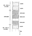
ここで、図7a,b,cに内視鏡装置100により同一の光量で同様の画像処理条件の下で観察した唇内側の拡大画像を示した。同図においては、中心波長445nmの青色レーザ光と蛍光体の励起発光光からなる白色照明光による観察画像(図7a)と、中心波長405nmの紫色レーザ光と中心波長445nmの青色レーザ光との光量比を50:50とした場合の観察画像(図7b)と、中心波長405nmの紫色レーザ光と中心波長445nmとの光量比を75:25とした場合の観察画像(図7c)を示している。なお、図7b,cにおいても中心波長445nmの青色レーザ光を励起光とする蛍光体からの励起発光光が照明光に含まれている。
図7a、図7b、図7cの観察画像は、照明光の波長によりa→b→cの順で表層からの観察深さが浅くなり、微細な毛細血管の映出量が増加している。つまり、照明光内における紫色レーザ光の割合を増加させるほど表層の毛細血管がより強調された画像が得られ、粘膜表層の毛細血管及び粘膜微細模様を、コントラストを高めてより明瞭に観察することができる。また、青色レーザ光と紫色レーザ光の光量比を無段階で自在に変更できるため、連続的に光量比を変えた際の観察画像の変化から、粘膜表層における立体的な血管構造を推察したり、所望の観察対象を選択的に明瞭に映出させたりすることが容易に行える。
このような、互いに近接した波長帯域となる紫色光と青色光に対して、紫色領域だけの光量を青色領域の光と区別して増減させることは、従来のハロゲンランプやキセノンランプとカラーフィルタ等の波長制限手段で実現することは難しい。光路中に波長制限手段を用いて発光スペクトルを狭帯域化すると、元々のハロゲンランプやキセノンランプの自体の光量が少ない上、紫色領域の光量は更に不足する。また、この紫色領域の光量を増やすために発光スペクトルの半値幅を拡げようとすると、照明光の狭帯域化が図れずに、所望の血管の画像強調が不十分となる。
そして、照明光の光量が不足する場合、一般的にはイメージセンサの感度を上げること、又はフレームレートを落とすことで光量不足に対処できるが、撮像時にイメージセンサの感度を上げると、撮像画像のノイズ成分が増加する不利がある。また、フレームレートを落として感度を増加させると、ぶれが大きくなって、却って観察画像が見にくくなる。本構成例では、光源としてレーザ光を用いるため、高強度の照明光が常時安定して得られ、観察画像を明るくでき、しかも低ノイズの良好な画質にできる。そして、遠景を撮像する場合でも必要十分な照度が得られる。
上記の光量比は、図2に示す光源制御部55が各光源51,53を制御することで変更するが、次に、この光量比を術者が観察画像を見ながら変更する方法を図8、図9を用いて説明する。
図8は内視鏡装置100による観察画像を表示する表示部15の表示画面71の例を示している。表示画面71には、内視鏡装置による観察画像を表示する内視鏡画像領域73と、通常の白色光照明による観察画像を内視鏡画像領域73に表示させる通常画像切り替えボタン75、紫色レーザ光の狭帯域照明光による観察画像を表示させる狭帯域光画像切り替えボタン77が設けられ、更に光量比を調整する調整用バー79とつまみ81が設けられている。そして、マウスやキーボード等の入力部17からの指示に基づいて、つまみ81を調整用バー79内でスライド移動させ、所望の観察画像となるように光量比を調整する。
図8は内視鏡装置100による観察画像を表示する表示部15の表示画面71の例を示している。表示画面71には、内視鏡装置による観察画像を表示する内視鏡画像領域73と、通常の白色光照明による観察画像を内視鏡画像領域73に表示させる通常画像切り替えボタン75、紫色レーザ光の狭帯域照明光による観察画像を表示させる狭帯域光画像切り替えボタン77が設けられ、更に光量比を調整する調整用バー79とつまみ81が設けられている。そして、マウスやキーボード等の入力部17からの指示に基づいて、つまみ81を調整用バー79内でスライド移動させ、所望の観察画像となるように光量比を調整する。
制御部67は、調整用バー79のつまみ81の位置に応じて光量比を決定し、この光量比に対応する各光源51,53の出射光量となるように各光源51,53を駆動する。ここで、光量比と各光源51,53の出射光量との関係は、光量比対応テーブルとして記憶部83(図2参照)に記憶されており、制御部67は、記憶部83の光量比対応テーブルを参照して各光源51,53の出射光量を求める。
上記のように、各光源51,53(図1参照)の光量を増減して所望の光量比に設定するに際し、制御部67は表示画面71で設定された光量比に基づいて、予め記憶された光量比対応テーブルを参照して各光源51,53の出射光量を決定する。これにより、各光源51,53それぞれの出射光量を内視鏡の術者が直接設定することなく、簡単な操作で所望の光量比となるように設定できる。
また、図9に示すように、光量比の変更は、画像信号のR,G,Bの各色成分の強度バランス、輝度、コントラストの各種調整の設定部85を代用して設定してもよく、あるいは光量比変更用のつまみ81の調整と併用して使用してもよい。これによれば、所望の観察対象を擬似カラー化して表現する等、任意に画像強調して表示することができ、表示画像の変更自由度が向上して、一層診断しやすい画像にできる。
次に、光源制御部55による各光源51,53の駆動方法について説明する。
図2に示す光源制御部55は、入力部17からの指示に基づいて各光源51,53の出射光量を制御する。各光源51,53は、図10に示すような印加電流と発光量との関係R1を有しており、各光源51,53への印加電流を制御することで所望の発光量を得ている。例えば、発光量Laを得るためには、印加電流をIbとして関係R1に基づく発光量Lbを確保し、更に、微調整代としての発光量LbとLaとの差ΔLを、印加電流にパルス変調されたパルス電流を重畳することで得る。
図2に示す光源制御部55は、入力部17からの指示に基づいて各光源51,53の出射光量を制御する。各光源51,53は、図10に示すような印加電流と発光量との関係R1を有しており、各光源51,53への印加電流を制御することで所望の発光量を得ている。例えば、発光量Laを得るためには、印加電流をIbとして関係R1に基づく発光量Lbを確保し、更に、微調整代としての発光量LbとLaとの差ΔLを、印加電流にパルス変調されたパルス電流を重畳することで得る。
例えば、図11に印加電流のパルス電流重畳波形を示すように、発光量Laは印加電流Ibをバイアスとするパルス電流により得られる。このようなバイアス電流制御とパルス変調制御により、設定可能な発光量のダイナミックレンジを広く確保できる。
この場合のパルス変調制御は、種々の駆動波形が利用できる。例えば、図12(a)に示すような撮像素子の画像1フレーム分の光蓄積時間と同期してオンオフを繰り返すパルス波形を用いれば、CCD、CMOSイメージセンサの暗電流による影響を受けにくくなり、画像の鮮鋭度が高くなる。また、図12(b)に示すような前記の光蓄積時間に対して十分に速い周期のパルス波形を用いれば、画像表示に関係するフリッカーの発生を軽減でき、しかも、レーザのスペックルによる画像ノイズも低減できる。更に、図12(c)に示すような、図12(a)のパルス波形のオン期間を図12(b)の速い周期のパルス波形とした(a)及び(b)の混合型のパルス波形を用いれば、フリッカー軽減以外の上記効果を享受できる。
また、図13に示すように、各光源51,53を交互に点灯して、発光量が交互に最大となるように制御すると、光源51,53を合わせた光源装置41の最大駆動電力を抑えることができ、被検体である生体への負担も軽減できる。また、各光源51,53の照明光による撮像画像を個別に取得することもでき、その場合、取得した画像の画像間演算も可能となり、画像処理の自由度が向上する。
図14にヘモグロビンの吸収波長帯と各光源51,53の発光波長との概略的な関係を示した。
血中に含まれるヘモグロビンは、前述のように400~420nm付近の波長に吸収の極大があり、ヘモグロビンの吸収波長帯に含まれるか、又は吸収波長帯に近い発光波長の各光源51,53からの出射光は、血管情報を高コントラストで捉えることができる。また、各光源51,53の発光波長がヘモグロビンの吸収波長帯を挟んで、それぞれ同程度の吸収率に設定されることにより、血管情報の強弱が各光源51,53の光量比によって影響を受けることがない。つまり、各光源51,53の光量比を変更しても、血管像自体の検出感度が一定に保たれる。
血中に含まれるヘモグロビンは、前述のように400~420nm付近の波長に吸収の極大があり、ヘモグロビンの吸収波長帯に含まれるか、又は吸収波長帯に近い発光波長の各光源51,53からの出射光は、血管情報を高コントラストで捉えることができる。また、各光源51,53の発光波長がヘモグロビンの吸収波長帯を挟んで、それぞれ同程度の吸収率に設定されることにより、血管情報の強弱が各光源51,53の光量比によって影響を受けることがない。つまり、各光源51,53の光量比を変更しても、血管像自体の検出感度が一定に保たれる。
そして、ヘモグロビンの吸収波長帯の最大ピーク波長を避け、吸収波長帯の裾野領域における適度な吸収率となる波長領域の光を照明光として使用することで、観察領域で生体組織から出血を生じた場合に、組織表面層に滲出した血液による吸収の影響を受けて観察画像が暗くなることが防止される。
以上説明した紫色レーザ光の狭帯域光による照明と、白色光による照明によって得られる観察画像は、フレーム毎に瞬時に切り替えることができる。図15は、内視鏡の術者が内視鏡挿入部を被検体内で移動させ、所望の観察位置で狭帯域光による観察を行い、次の観察位置へ移動させる際の、表示部15(図1,2参照)の表示画像の様子を概略的に示している。
白色光観察による通常の表示画像から狭帯域光観察による表示画像への切り替え、及びこれと逆方向への切り替えは、撮像素子21の撮像画像(R,G,B三色のフルカラー画像)1フレーム単位でも切り替えが可能である。このため、内視鏡挿入部を移動させながら観察する場合であっても、リアルタイムで色ずれのない画像を表示でき、術者に違和感を生じさせることがない。つまり、内視鏡の素早い動きに対しても確実に追従する良好な観察画像を提供でき、内視鏡装置の操作性を向上できる。
また、表示部15における観察画像の表示パターンとしては、白色光観察時の通常画像と、狭帯域光観察時の狭帯域光画像とを自在に配置できる。例えば、図16に示すように、通常画像と狭帯域光画像とを同一画面内でそれぞれ個別の領域に配置して、同時に表示させることで、通常画像と、特定の情報が強調された狭帯域光画像とを対比観察することが容易になる。この場合、白色光による通常画像用に青色レーザ光源51を点灯させて撮像し、次のフレームでは狭帯域光画像用に青色レーザ光源51と紫色レーザ光源53とを同時に点灯させて撮像することを繰り返し、得られた通常画像と狭帯域光画像をそれぞれの表示領域に表示する。
また、図17においては、通常画像の中に所望の範囲の狭帯域光画像を重ね合わせて同時に表示する、所謂、P in P(Picture in Picture)機能の表示画面を示している。狭帯域光画像の表示範囲は、入力部17(図1,2参照)からの指示により、通常画像内の任意の位置、任意の大きさに設定することができる。そして、狭帯域光画像の表示範囲内には、通常画像における被検体の表示位置と同一位置の画像が表示されている。これにより、同一位置における対比観察が一層容易となる。なお、上記の表示パターンは一例であって、狭帯域光画像の中に通常画像を埋め込む表示形態であってもよく、その他任意に組み合わせた表示が行えることは言うまでもない。
次に、青色レーザ光と紫光レーザ光の光量比の設定について説明する。
上記の説明において、図2に示す青色レーザ光源51、紫色レーザ光源53からの出射光の光量比を、入力部17からの指示により光源制御部55が任意に設定できるとした。ここでは、予め複数種の光量比を登録しておき、入力部17からいずれかの光量比を指定する場合を説明する。
上記の説明において、図2に示す青色レーザ光源51、紫色レーザ光源53からの出射光の光量比を、入力部17からの指示により光源制御部55が任意に設定できるとした。ここでは、予め複数種の光量比を登録しておき、入力部17からいずれかの光量比を指定する場合を説明する。
例えば、血管画像の内視鏡観察においては、内視鏡の術者毎に青レーザ光と紫色レーザ光の光量比の嗜好が異なることがある。例えば、術者Aは紫色レーザ光λa、青色レーザ光λbの光量比を60:40とした観察画像を好ましく感じ、術者Bは75:25の光量比を好ましく感じる等、嗜好による違いが生じることがある。その場合、図18に示すように、キー情報となる術者名と、術者の好みの光量比とを関係付けた光量比情報を、記憶部83(図2参照)等に光量比テーブルとして予め登録しておく。そして、入力部17から術者名に対応する情報が入力されると、制御部67は、記憶部83の光量比テーブルを参照して所望の光量比を自動的に設定する。これにより、内視鏡の術者の嗜好に応じた光量比に設定できる。
また、内視鏡の個体によっても光学特性が異なる場合があるので、上記キー情報とした術者名に代えて、内視鏡の個体を識別する個体識別情報をキー情報としてもよい。その場合、内視鏡の個体毎に付与された番号、機種名等を用いて、これに対応する光量比の情報を光量比テーブルとして予め登録しておく。これにより、内視鏡の個体毎の種類や特性に応じて、最適な光量比に設定することができる。
更に、任意の複数種の光量比をプリセットしておき、術者が簡単な操作により自由に選択できる構成としてもよい。例えば、図19に表示部15による表示例を示すように、プリセットされた複数種の光量比を、GUI(Graphical User Interface)の「選択ボタン」87として表示して、術者や助手が表示部15(図1,2参照)を見て入力部17を操作することで自在に選択できるようにする。また、表示部15をタッチパネルとすれば、術者が観察時に注視している表示部15に対し、選択ボタン87を直接タッチすることで、スイッチ操作をより直感的に素早く行える。また、光量比の変更により変化する各観察画像を、術者は目を離すことなく比較でき、微妙な画像変化をより確実に認識できる。
また、光量比の切り替えは、表示部15への表示パターンから行うことに限らず、図1に示す内視鏡11の操作部23に設けたスイッチ89を切り替えスイッチとして操作する構成としてもよい。操作部23にスイッチ89を設けることで、術者が内視鏡11から手を離すことなく光量比の変更が迅速、かつ簡単に行えて、内視鏡の操作性が向上する。
このスイッチ89としては、トグルスイッチ、プッシュスイッチ、スライドスイッチ、ロータリースイッチ等の各種スイッチが利用でき、図20に示すように、一回の押下操作の度に、又は多接点スイッチの接点位置により、予めプリセットされた異なる光量比が順次に設定される。例えば、図2の青色レーザ光源51と蛍光体57による白色光で観察する通常光観察と、紫色レーザ光源53からの狭帯域光を所定の割合で白色光に重畳した狭帯域光観察A,B,C,・・・、又は狭帯域光だけの狭帯域光観察等、複数種の光量比の観察光モードを順次に選択できるようにする。
スイッチ操作が押下操作等の繰り返しであるとスイッチ89を目視確認する必要がなく、表示部15を注視しながらスイッチ操作できる。これにより、診断に適した照明光に簡単に切り替えできる。なお、光量比を切り替えるスイッチ89は、プリセットされた光量比を切り替えることに限らず、光量比を連続的に変化させるボリュームスイッチやスライドスイッチとしてもよい。その場合は、光量比を観察対象に応じて最適に調整することが容易となる。また、スイッチ操作により光量比を連続的に変更することで、観察画像の連続的な変化を観察でき、血管構造のより正確な把握が可能となる。
次に、光量比の変更に伴って発生する観察画像の色味変化を補正することについて説明する。
図4に示す画像処理部65には、画像信号R,G,Bが入力されて、この画像信号R,G,Bは輝度算出部65aにより輝度の正規化が行われ、Rnorm,Gnorm,Bnormの画像データに変換される。これら正規化された画像データRnorm,Gnorm,Bnormは、光量比に応じた色調への補正が色合わせ部65bで行われる。即ち、色合わせ部65bは、色調補正後の画像データRadj,Gadj,Badjを、(1)式で示すような演算により求める。
図4に示す画像処理部65には、画像信号R,G,Bが入力されて、この画像信号R,G,Bは輝度算出部65aにより輝度の正規化が行われ、Rnorm,Gnorm,Bnormの画像データに変換される。これら正規化された画像データRnorm,Gnorm,Bnormは、光量比に応じた色調への補正が色合わせ部65bで行われる。即ち、色合わせ部65bは、色調補正後の画像データRadj,Gadj,Badjを、(1)式で示すような演算により求める。

ここで、kR、kG、kBは、それぞれ各色の色変換係数であり、撮像時に設定された光量比に応じて定められる。図21に光量比に対応する各色の色変換係数を定めた色変換係数テーブルを示した。色変換係数kR、kG、kBは、それぞれ各光量比に対応してR00~R100,G00~G100、B00~B100として設定されており、記憶部83(図2参照)に記憶されている。撮像時に用いた光量比に対応する色変換係数を(1)式に代入することで、色調補正された画像データRadj,Gadj,Badjが得られる。
この色変換係数は、図21に示すテーブルとして表すことに限らず、数式化して表してもよく、また、代表点のみ数値化して他の点を補間演算により求めてもよい。その場合、記憶部83に記憶する情報量を軽減できる。
以上説明した内視鏡装置100によれば、紫色レーザ光(及び青色レーザ光)、即ち、特に血管の観察に適した短い波長帯域の照明光を用いることにより、生体組織表層の微細血管を画像強調して観察でき、血管の微細構造の観察が容易になる。そして、紫色レーザ光と青色レーザ光(白色光)の出射光の光量比を連続的に変更できるため、生体組織表層から深さ方向に変化する血管構造の観察が簡単に行え、生体組織のより表層部の血管構造が明瞭に把握できる。よって、白色光や特殊光による生体組織の観察時に、生体組織の所望の組織情報を、診断に適したより明瞭な状態で取得でき、内視鏡診断を円滑に行うことができる。
そして、上記の内視鏡装置100が、被観察領域を拡大観察可能な撮像光学系を備えた、所謂、拡大内視鏡の構成とした場合は、生体組織表層の微小血管と粘膜微細模様との分離性を高めて、より高度な内視鏡診断が可能となる。つまり、拡大観察により、微小血管の口径不同、形状不均一、拡張、蛇行等の異変、粘膜微細模様の消失や不整微小化等の異変、等の異変の存在が確認でき、例えば腺癌の種類を診断する等の有益な情報を提供できる。
次に、内視鏡装置の他の構成例を説明する。
まず、ヘモグロビンと酸化ヘモグロビンの吸収特性の違いを利用して、観察画像内の血液の酸素濃度分布を求める内視鏡装置について説明する。
図22に波長450nm~700nmにおける酸素濃度の低いヘモグロビンHbと酸素飽和した酸化ヘモグロビンHbO2の吸収スペクトルを示した。観察用の照明光として、ヘモグロビンHbと、酸化ヘモグロビンHbO2との吸収が等しくなる等吸収点の波長λ1と、双方の吸収が異なる波長λ2とを選択して、波長λ1の照明光による観察画像の輝度Ab1と、波長λ2の照明光による観察画像の輝度Ab2を求める。
まず、ヘモグロビンと酸化ヘモグロビンの吸収特性の違いを利用して、観察画像内の血液の酸素濃度分布を求める内視鏡装置について説明する。
図22に波長450nm~700nmにおける酸素濃度の低いヘモグロビンHbと酸素飽和した酸化ヘモグロビンHbO2の吸収スペクトルを示した。観察用の照明光として、ヘモグロビンHbと、酸化ヘモグロビンHbO2との吸収が等しくなる等吸収点の波長λ1と、双方の吸収が異なる波長λ2とを選択して、波長λ1の照明光による観察画像の輝度Ab1と、波長λ2の照明光による観察画像の輝度Ab2を求める。
これら画像の輝度Ab1,Ab2の比は、血液中の酸素濃度を表す指標となり、生体組織の代謝状態の変化をモニタできる。一般的に癌の領域は酸素濃度が低いといわれ、酸素濃度は内視鏡診断に有益な情報となる。
上記の酸素濃度分布を求める内視鏡装置の構成としては、図23に光源装置41と内視鏡11の構成例を示すように、内視鏡装置200には、光源装置41に複数の光源が追加される。ここでは、等吸収点の照明光として、例えば、中心波長515nmの青緑色レーザ光源91による青緑色レーザ光を用い、吸収が異なる波長の照明光として、中心波長630nmの赤色レーザ光源93による赤色レーザ光を用いる。勿論、酸素濃度分布の測定を主とする場合には、紫色レーザ光源53は省略することもできる。なお、図中の符号は図2と同じ部材に対しては同一の符号を付与することで、その説明を省略する。
なお、上記構成の光ファイバ45A,45B,45C,45Dは、使用する波長に応じてそれぞれ最適なファイバを選定して用いることが好ましい。光ファイバのコアは、水酸基(OH-)濃度の高/低により伝送損失が変化する波長依存性を有し、赤外域の特定の波長では可視域の波長とは異なる吸収率となる。そのため、光源の波長が650nm以下の場合は高水酸基濃度のコアの光ファイバを用い、650nmを超える場合は低水酸基濃度のコアの光ファイバを用いるようにする。
酸素濃度分布を求めるには、まず、青緑色レーザ光源91からの青緑色レーザ光を照明光として被観察領域を撮像し、次いで、赤色レーザ光源93からの赤色レーザ光を照明光として被観察領域を撮像する。撮像時には、観察画像データの平均輝度値等が一定になるように、各光源91,93の出射光量をそれぞれ調整する。そして、得られた各観察画像の輝度Ab1,Ab2から、酸素濃度指標Oindxを各画素毎に(2)式により求める。
Oindx = k・(Ab2/Ab1) ・・・(2)
ただし、kは係数である。
Oindx = k・(Ab2/Ab1) ・・・(2)
ただし、kは係数である。
これにより、酸素濃度指標Oindxの分布画像が得られ、観察画像内の酸素濃度の分布状態が把握できる。
また、青緑色レーザ光源91と、赤色レーザ光源93は、青色レーザ光源51や紫色レーザ光源53と同様に、光源制御部55により出射光の光量がそれぞれ個別に変更でき、観察対象や手技の内容等に応じて各出射光の光量比が調整される。そして、各レーザ光源91,93は、撮像信号の1フレーム内でそれぞれ発光させて、その光量比を適宜調整してもよい。青緑色レーザ光は生体組織の微細血管や発赤の観察に好適であり、赤色レーザ光は生体組織の深部血管の観察に好適となる。したがって、これらの各レーザ光の出射光の光量比を変更することで、前述同様に、深さ方向に異なる領域からの情報、異なる対象からの情報を画像強調して表示させることができる。
また、撮像信号の1フレーム内で各光源を同時に発光させても、撮像素子21から出力されるR,G,Bの各画像信号から、青緑色レーザ光源91による光成分、赤色レーザ光源93による光成分、又は励起光量をそれぞれ分離して検出することができる。
このように、白色光に対する青緑色レーザ光の光量比、白色光に対する赤色レーザ光の光量比、あるいは、青緑色レーザ光と赤色レーザ光との光量比を、それぞれ任意に、かつ連続的に変更可能とすることで、所望の観察対象の視認性を高めて表示できる。そして、内視鏡の照明光種類を増やして多機能化することで、内視鏡診断時に予期しない観察の必要性が生じた場合でも、内視鏡を被検体から抜去することなく、速やかに観察対象に応じた適切な照明光での観察が可能となる。なお、白色光を青色レーザ光と蛍光体の励起発光光により生成することに代えて、ハロゲンランプ等の白色光源を用いる構成にすることもできる。その場合、青色レーザ光の光量と白色光の光量とを個別に制御することができ、光量比の調整をより細かに行える。
次に、光源装置41から内視鏡11までの光路を1本の光ファイバ45で構成した内視鏡装置について説明する。
図24に光源装置41と内視鏡11の構成例を示した。内視鏡装置300は、中心波長445nmの青色レーザ光源51からの青色レーザ光が、図示しない集光レンズを介して光ファイバ45Aに導入されるまでの光路途中に、中心波長405nmの紫色レーザ光源53からの紫色レーザ光を合流させる光カップリグ手段としてのダイクロイックプリズム95を備える。
図24に光源装置41と内視鏡11の構成例を示した。内視鏡装置300は、中心波長445nmの青色レーザ光源51からの青色レーザ光が、図示しない集光レンズを介して光ファイバ45Aに導入されるまでの光路途中に、中心波長405nmの紫色レーザ光源53からの紫色レーザ光を合流させる光カップリグ手段としてのダイクロイックプリズム95を備える。
光ファイバ45Aの光出射側に配置される蛍光体97は、青色レーザ光源51からの青色レーザ光の一部を吸収して緑色~黄色に励起発光し、吸収されず透過した青色レーザ光と合わせて白色光を形成すると共に、紫色レーザ光源53からの紫色レーザ光を殆ど吸収せずに透過させる性質を有する。そのため、蛍光体97には、青色レーザ光により高効率で励起発光して、青色レーザ光と合わせて白色光が形成される材料と、紫色レーザ光に対しては、蛍光体の発光光量が少なくなる材料とを選択して用いる。
蛍光体97による波長変換には、原理的に発生する発熱等の波長変換損失(ストークスロス)が存在する。そのため、発光波長の長い励起波長を選択した方が蛍光体の発光効率が高く、蛍光体の発熱を抑制する上で有利となることが知られている。そこで本構成例では、長波長側のレーザ光により白色光を生成して、発光効率を高めている。
図24に示す光源装置41と蛍光体97による照明光の発光スペクトルの例を図25に示した。図25に示すように、紫色レーザ光による蛍光体97の励起発光量は、青色レーザ光による励起発光量に比較して、数分の一(少なくとも1/3、望ましくは1/5、更に望ましくは1/10以下)であることが望ましい。
以上、本構成によれば、青色レーザ光と紫色レーザ光の光路をダイクロイックプリズム95により統合させるため、光源装置41から蛍光体97までを1本の光ファイバ45Aで導光させ、しかも、照明光の出射口を蛍光体97の1箇所に収められるので、スペース効率を高めて内視鏡挿入部の細径化に寄与できる。
また、青色レーザ光源51、紫色レーザ光源53の他に他のレーザ光源を備える場合であっても、同様にダイクロイックプリズム等の光カップリング手段を介して光路を統合すればよい。また、蛍光体97についても、他のレーザ光源の波長に励起しない、又は励起しにくい蛍光物質を用いればよい。
ここで、本構成例における具体的な蛍光体97の材料としては、例えば、特開2006-2115号公報に記載のような、添加元素として鉛(Pb)を含み4硫化2ガリウムカルシウム(CaGa2S4)を母体とする結晶性の固体蛍光材料、あるいは、添加元素として鉛(Pb)とセリウム(Ce)を含み4硫化2ガリウムカルシウム(CaGa2S4)を母体とする結晶性の固体蛍光材料が使用できる。この蛍光体材料によれば、約460nm~約660nmのほぼ可視全域に至る蛍光を得ることができ、白色光照明時における演色性が向上する。
また、この他にも、緑色蛍光体であるLiTbW2O8(小田喜 勉、“白色LED用蛍光体について”、電子情報通信学会技術研究報告ED2005-28, CFM2005-20,SDM2005-28, pp.69-74(2005-05)等を参照)、ベータサイアロン(β-sialon:Eu)青色蛍光体(広崎 なお登、解 栄軍、佐久間 健、“サイアロン系信蛍光体とそれを用いた白色LEDの開発”、応用物理学会誌 第74巻、第11号、pp.1449-1452(2005)、あるいは、山元 明 東京工科大パイオニクス学部、応用物理学会誌 第76巻 第3号、p.241(2007)を参照)、CaAlSiN3赤色蛍光体等を組み合わせて用いることができる。ベータサイアロンは、β型窒化ケイ素結晶にアルミニウムと酸とが固溶したSi6-zAl2O2N8-z(zは固溶量)の組成で示される結晶である。蛍光体97は、これらLiTbW2O8とベータサイアロン、CaAlSiN3を混在させたものとしてもよく、また、これらの蛍光体を層状に重ねた構成としてもよい。
上記例示した各蛍光体は、青色レーザ光源51からの青色レーザ光により励起され、他の紫色レーザ光源53からの紫色レーザ光によっては励起発光しない、つまり、蛍光体固有の主要な励起波長帯に他の光源の発光波長が含まれないようにする。
以上説明した内視鏡装置においては、白色光を青色レーザ光と蛍光体57,97の励起発光光とによって生成したが、これに限らず、例えば、青色レーザ光により緑色の励起発光を発生させる蛍光体と、紫色レーザ光により赤色の励起発光光を発生させる蛍光体を用いた構成にする等、白色光の生成には種々の光源、蛍光体との組合せが可能である。
以上の通り、本明細書には次の事項が開示されている。
(1) 複数の光源の出射光を用いて照明光を得る内視鏡用照明装置であって、
半導体発光素子を発光源とする第1の光源と、
前記第1の光源とは異なる発光波長の半導体発光素子を発光源とする第2の光源と、
前記第1、第2の光源の少なくとも一方からの出射光により励起発光する波長変換部材と、
前記第1の光源からの出射光と前記第2の光源からの出射光との光量比を変更する光量比変更手段と、
を備えた内視鏡用照明装置。
この内視鏡用照明装置によれば、第1の光源と第2の光源の出射光の光量比が変更自在であるので、第1の光源からの出射光成分が多い照明光と、第2の光源からの出射光成分が多い照明光と、その中間の照明光とを任意に発生させることができる。したがって、生体組織の吸収特性及び散乱特性に応じて、診断に適した照明光を提供でき、生体組織の所望の組織情報が、より明瞭な状態で取得可能となる。
(2) (1)の内視鏡用照明装置であって、
前記第1の光源と前記第2の光源のうち、少なくとも一方の半導体発光素子の発光波長が400nm乃至470nmの範囲に含まれる内視鏡用照明装置。
この内視鏡用照明装置によれば、400nm乃至470nmの半導体発光素子の光を使用することで、特に生体組織の表層部における血管を強調させて観察できる。
前記第1の光源と前記第2の光源のうち、少なくとも一方の半導体発光素子の発光波長が400nm乃至470nmの範囲に含まれる内視鏡用照明装置。
この内視鏡用照明装置によれば、400nm乃至470nmの半導体発光素子の光を使用することで、特に生体組織の表層部における血管を強調させて観察できる。
(3) (1)又は(2)の内視鏡用照明装置であって、
前記波長変換部材は、該波長変換部材が励起光により発光する発光光と、前記第1、第2の光源の少なくとも一方からの出射光と、によって白色光を生成する蛍光体である内視鏡用照明装置。
この内視鏡用照明装置によれば、半導体発光素子からの光を励起光とした波長変換部材の発光により白色光を生成するため、高い発光効率で高強度の白色光が得られる。また、半導体発光素子を励起光源として用いるため、白色光の強度を容易に調整でき、しかも、白色光の色温度、色度の変化が少ない。
前記波長変換部材は、該波長変換部材が励起光により発光する発光光と、前記第1、第2の光源の少なくとも一方からの出射光と、によって白色光を生成する蛍光体である内視鏡用照明装置。
この内視鏡用照明装置によれば、半導体発光素子からの光を励起光とした波長変換部材の発光により白色光を生成するため、高い発光効率で高強度の白色光が得られる。また、半導体発光素子を励起光源として用いるため、白色光の強度を容易に調整でき、しかも、白色光の色温度、色度の変化が少ない。
(4) (1)~(3)のいずれか1つの内視鏡用照明装置であって、
前記第1、第2の光源とは異なる発光波長の半導体発光素子を発光源とする少なくとも1つの第3の光源を、光源毎に発光波長を異ならせて更に備えた内視鏡用照明装置。
この内視鏡用照明装置によれば、発光波長の異なる第3の光源を更に備えることで、照明光の波長帯域を拡大でき、照明光の波長選択の自由度が向上する。これにより、例えば、紫色光や青色光による血管強調画像、緑色光と赤色光とによる酸素濃度の分布画像等、種々の画像形成用の照明光を得ることができる。
前記第1、第2の光源とは異なる発光波長の半導体発光素子を発光源とする少なくとも1つの第3の光源を、光源毎に発光波長を異ならせて更に備えた内視鏡用照明装置。
この内視鏡用照明装置によれば、発光波長の異なる第3の光源を更に備えることで、照明光の波長帯域を拡大でき、照明光の波長選択の自由度が向上する。これにより、例えば、紫色光や青色光による血管強調画像、緑色光と赤色光とによる酸素濃度の分布画像等、種々の画像形成用の照明光を得ることができる。
(5) (1)~(4)のいずれか1つの内視鏡用照明装置であって、
前記第1の光源から前記波長変換部材までの光路途中に配置され、少なくとも前記第2の光源からの出射光を前記第1の光源からの出射光と合わせて前記波長変換部材へ導光する光カップリング手段を備えた内視鏡用照明装置。
この内視鏡用照明装置によれば、光カップリング手段から波長変換部材までの間が一系統の光路で済み、内視鏡用照明装置を内視鏡装置に組み込む際に、スペース効率をより高めた簡素な構成にできる。
前記第1の光源から前記波長変換部材までの光路途中に配置され、少なくとも前記第2の光源からの出射光を前記第1の光源からの出射光と合わせて前記波長変換部材へ導光する光カップリング手段を備えた内視鏡用照明装置。
この内視鏡用照明装置によれば、光カップリング手段から波長変換部材までの間が一系統の光路で済み、内視鏡用照明装置を内視鏡装置に組み込む際に、スペース効率をより高めた簡素な構成にできる。
(6) (2)~(5)のいずれか1つの内視鏡用照明装置であって、
前記第1の光源及び前記第2の光源の各発光波長のうち、いずれか一方がヘモグロビンの吸収波長帯の最大ピーク波長を挟んだ短波長側に、他方が長波長側にそれぞれ設定された内視鏡用照明装置。
この内視鏡用照明装置によれば、血管情報を高コントラストで捉えることができる。また、ヘモグロビンの吸収波長の極大付近の照明光成分を少なくすることで、組織表面層に滲出した血液の吸収によって観察画像が暗くなることを防止できる。
前記第1の光源及び前記第2の光源の各発光波長のうち、いずれか一方がヘモグロビンの吸収波長帯の最大ピーク波長を挟んだ短波長側に、他方が長波長側にそれぞれ設定された内視鏡用照明装置。
この内視鏡用照明装置によれば、血管情報を高コントラストで捉えることができる。また、ヘモグロビンの吸収波長の極大付近の照明光成分を少なくすることで、組織表面層に滲出した血液の吸収によって観察画像が暗くなることを防止できる。
(7) (1)~(6)のいずれか1つの内視鏡用照明装置であって、
前記光量比変更手段が、前記各光源からの出射光の光量をそれぞれ独立して変更する内視鏡用照明装置。
この内視鏡用照明装置によれば、出射光の光量を光源毎に変更自在にすることで、各光源光により最終的に形成される照明光の分光特性を、自由度を高めて調整できる。
前記光量比変更手段が、前記各光源からの出射光の光量をそれぞれ独立して変更する内視鏡用照明装置。
この内視鏡用照明装置によれば、出射光の光量を光源毎に変更自在にすることで、各光源光により最終的に形成される照明光の分光特性を、自由度を高めて調整できる。
(8) (1)~(7)のいずれか1つの内視鏡用照明装置であって、
所望の光量比を指定する光量比情報が入力される入力手段を更に備え、
前記光量比変更手段が、前記入力手段に入力された光量比情報に基づいて、前記所望の光量比となる前記各光源の出射光量をそれぞれ決定する内視鏡用照明装置。
この内視鏡用照明装置によれば、入力手段から入力のあった光量比情報により、光量比が指定され、この光量比となるような光源の出射光量が決定される。つまり、光量比を指定した通りに自在に変更できる。
所望の光量比を指定する光量比情報が入力される入力手段を更に備え、
前記光量比変更手段が、前記入力手段に入力された光量比情報に基づいて、前記所望の光量比となる前記各光源の出射光量をそれぞれ決定する内視鏡用照明装置。
この内視鏡用照明装置によれば、入力手段から入力のあった光量比情報により、光量比が指定され、この光量比となるような光源の出射光量が決定される。つまり、光量比を指定した通りに自在に変更できる。
(9) (8)の内視鏡用照明装置であって、
複数種の光量比をキー情報と関係付けた光量比テーブルが記憶された記憶手段を更に備え、
前記光量比情報が前記キー情報を含み、
前記光量比変更手段が、前記入力手段から入力された光量比情報に含まれるキー情報に基づき、前記光量比テーブルを参照して前記所望の光量比を決定する内視鏡用照明装置。
この内視鏡用照明装置によれば、光量比情報に含まれるキー情報に基づいて、光量比テーブルを参照して所望の光量比が決定される。つまり、光量比テーブルに予め光量比をキー情報毎に登録しておくことで、キー情報を指定するだけで、このキー情報に対応する光量比が自動的に決定される。
複数種の光量比をキー情報と関係付けた光量比テーブルが記憶された記憶手段を更に備え、
前記光量比情報が前記キー情報を含み、
前記光量比変更手段が、前記入力手段から入力された光量比情報に含まれるキー情報に基づき、前記光量比テーブルを参照して前記所望の光量比を決定する内視鏡用照明装置。
この内視鏡用照明装置によれば、光量比情報に含まれるキー情報に基づいて、光量比テーブルを参照して所望の光量比が決定される。つまり、光量比テーブルに予め光量比をキー情報毎に登録しておくことで、キー情報を指定するだけで、このキー情報に対応する光量比が自動的に決定される。
(10) (9)の内視鏡用照明装置であって、
前記キー情報が、内視鏡装置の術者の識別情報である内視鏡用照明装置。
この内視鏡用照明装置によれば、内視鏡の術者の嗜好に応じて、術者毎に任意の光量比に設定できる。
前記キー情報が、内視鏡装置の術者の識別情報である内視鏡用照明装置。
この内視鏡用照明装置によれば、内視鏡の術者の嗜好に応じて、術者毎に任意の光量比に設定できる。
(11) (9)の内視鏡用照明装置であって、
前記キー情報が、内視鏡装置の個体識別情報である内視鏡用照明装置。
この内視鏡用照明装置によれば、内視鏡装置の個体毎の種類や特性に応じて、個体毎に光量比を設定することができる。
前記キー情報が、内視鏡装置の個体識別情報である内視鏡用照明装置。
この内視鏡用照明装置によれば、内視鏡装置の個体毎の種類や特性に応じて、個体毎に光量比を設定することができる。
(12) (9)~(11)のいずれか1つの内視鏡用照明装置であって、
前記入力手段が、前記光量比テーブルに設定された複数種の光量比のいずれかを指定する切り替えスイッチである内視鏡用照明装置。
この内視鏡用照明装置によれば、切り替えスイッチの操作により、複数種の光量比の中から所望の光量比を任意に指定でき、光量比の切り替えが迅速かつ簡単に行える。
前記入力手段が、前記光量比テーブルに設定された複数種の光量比のいずれかを指定する切り替えスイッチである内視鏡用照明装置。
この内視鏡用照明装置によれば、切り替えスイッチの操作により、複数種の光量比の中から所望の光量比を任意に指定でき、光量比の切り替えが迅速かつ簡単に行える。
(13) (1)~(12)のいずれか1つの内視鏡用照明装置からの照明光を、体腔内に挿入される内視鏡挿入部の先端側から出射する照明手段と、
前記照明光が照射された被観察領域を撮像する撮像素子が前記内視鏡挿入部に搭載され、観察画像となる画像信号を出力する撮像手段と、
を備えた内視鏡装置。
この内視鏡装置によれば、第1の光源と第2の光源からの各出射光の光量比が所望の光量比に設定された照明光を被観察領域に照射し、この被観察領域を撮像素子により撮像することで、光量比に対応した観察画像が得られる。つまり、診断に適した照明光を照射でき、生体組織の所望の組織情報を、より明瞭な状態で取得可能となる。
前記照明光が照射された被観察領域を撮像する撮像素子が前記内視鏡挿入部に搭載され、観察画像となる画像信号を出力する撮像手段と、
を備えた内視鏡装置。
この内視鏡装置によれば、第1の光源と第2の光源からの各出射光の光量比が所望の光量比に設定された照明光を被観察領域に照射し、この被観察領域を撮像素子により撮像することで、光量比に対応した観察画像が得られる。つまり、診断に適した照明光を照射でき、生体組織の所望の組織情報を、より明瞭な状態で取得可能となる。
(14) (13)の内視鏡装置であって、
少なくとも前記第1の光源及び前記第2の光源を、前記撮像素子の画像信号1フレーム内に発光させる光源制御手段を備えた内視鏡装置。
この内視鏡用照明装置によれば、画像信号1フレーム内で各光源を発光させて撮像素子により撮像することで、複数の光源からの出射光が共に被観察領域に照射された観察画像を得ることができる。
少なくとも前記第1の光源及び前記第2の光源を、前記撮像素子の画像信号1フレーム内に発光させる光源制御手段を備えた内視鏡装置。
この内視鏡用照明装置によれば、画像信号1フレーム内で各光源を発光させて撮像素子により撮像することで、複数の光源からの出射光が共に被観察領域に照射された観察画像を得ることができる。
(15) (14)の内視鏡装置であって、
前記光源制御手段が、少なくとも前記第1の光源及び前記第2の光源を、前記撮像素子の画像信号1フレーム内で互いに異なるタイミングで発光させる内視鏡装置。
この内視鏡装置によれば、各光源を同時に発光させる必要がなくなり、被検体への負担や装置の消費電力を抑えることができる。
前記光源制御手段が、少なくとも前記第1の光源及び前記第2の光源を、前記撮像素子の画像信号1フレーム内で互いに異なるタイミングで発光させる内視鏡装置。
この内視鏡装置によれば、各光源を同時に発光させる必要がなくなり、被検体への負担や装置の消費電力を抑えることができる。
(16) (13)~(15)のいずれか1つの内視鏡装置であって、
前記撮像素子から出力された画像信号に基づく表示用観察画像を生成する画像処理手段と、
前記表示用観察画像を含む情報を表示する表示手段と、
を備えた内視鏡装置。
この内視鏡装置によれば、撮像素子からの画像信号の情報を表示手段に表示させることで、観察画像の確認が容易となり内視鏡診断をより円滑に実施できる。
前記撮像素子から出力された画像信号に基づく表示用観察画像を生成する画像処理手段と、
前記表示用観察画像を含む情報を表示する表示手段と、
を備えた内視鏡装置。
この内視鏡装置によれば、撮像素子からの画像信号の情報を表示手段に表示させることで、観察画像の確認が容易となり内視鏡診断をより円滑に実施できる。
(17) (16)の内視鏡装置であって、
前記表示手段が、前記第1の光源からの出射光及び前記波長変換部材からの励起発光光を含む可視光下で撮像した第1の画像情報と、
前記可視光に加えて前記第2の光源からの出射光を含む照明光下で撮像した第2の画像情報とを、同一画面内で同時に表示する内視鏡装置。
この内視鏡装置によれば、波長帯域の広い可視光を照明光としたときの観察画像である第1の画像情報と、狭帯域光を含む照明光による観察画像である第2の画像情報とを、表示手段の同一画面内で同時に表示する。これにより、通常の観察画像と、特定の情報が強調された画像とを対比観察することが容易になる。
前記表示手段が、前記第1の光源からの出射光及び前記波長変換部材からの励起発光光を含む可視光下で撮像した第1の画像情報と、
前記可視光に加えて前記第2の光源からの出射光を含む照明光下で撮像した第2の画像情報とを、同一画面内で同時に表示する内視鏡装置。
この内視鏡装置によれば、波長帯域の広い可視光を照明光としたときの観察画像である第1の画像情報と、狭帯域光を含む照明光による観察画像である第2の画像情報とを、表示手段の同一画面内で同時に表示する。これにより、通常の観察画像と、特定の情報が強調された画像とを対比観察することが容易になる。
(18) (16)又は(17)の内視鏡装置であって、
前記表示手段が、前記第1の光源からの出射光及び前記波長変換部材からの励起発光光を含む可視光下で撮像した第1の画像情報と、
前記可視光に加えて前記第2の光源からの出射光を含む照明光下で撮像した第2の画像情報とのいずれか一方の画像情報を、互いに重ね合わせて同時に表示する内視鏡装置。
この内視鏡装置によれば、通常の観察画像と、特定の情報が強調された画像とが重ね合わされて表示され、対比観察することが容易となる。
前記表示手段が、前記第1の光源からの出射光及び前記波長変換部材からの励起発光光を含む可視光下で撮像した第1の画像情報と、
前記可視光に加えて前記第2の光源からの出射光を含む照明光下で撮像した第2の画像情報とのいずれか一方の画像情報を、互いに重ね合わせて同時に表示する内視鏡装置。
この内視鏡装置によれば、通常の観察画像と、特定の情報が強調された画像とが重ね合わされて表示され、対比観察することが容易となる。
(19) (13)~(18)のいずれか1項記載の内視鏡装置であって、
前記画像処理手段から出力される観察画像を含む情報を記録する記録手段を備え、
前記記録手段が、前記観察画像と前記光量比とを関係付けて記録する内視鏡装置。
この内視鏡装置によれば、観察画像が、この観察画像の撮像時に設定された光量比と関係づけられて記録されるため、記録された観察画像に対して、撮像時の光量比に応じて画像処理する等、観察画像の活用範囲を拡大できる。
前記画像処理手段から出力される観察画像を含む情報を記録する記録手段を備え、
前記記録手段が、前記観察画像と前記光量比とを関係付けて記録する内視鏡装置。
この内視鏡装置によれば、観察画像が、この観察画像の撮像時に設定された光量比と関係づけられて記録されるため、記録された観察画像に対して、撮像時の光量比に応じて画像処理する等、観察画像の活用範囲を拡大できる。
本発明の内視鏡用光源装置および内視鏡装置によれば、白色光や特定の波長帯域の特殊光を用いた生体組織の観察時に、生体組織の所望の組織情報を、診断に適したより明瞭な状態で取得できる。
本発明は上記の実施形態に限定されるものではなく、明細書の記載、並びに周知の技術に基づいて、当業者が変更、応用することも本発明の予定するところであり、保護を求める範囲に含まれる。
本出願は、2009年7月6日出願の日本特許出願番号2009-159962に基づくものであり、その内容はここに参照として取り込まれる。
本発明は上記の実施形態に限定されるものではなく、明細書の記載、並びに周知の技術に基づいて、当業者が変更、応用することも本発明の予定するところであり、保護を求める範囲に含まれる。
本出願は、2009年7月6日出願の日本特許出願番号2009-159962に基づくものであり、その内容はここに参照として取り込まれる。
11 内視鏡
13 制御装置
15 表示部
17 入力部
19 内視鏡挿入部
21 撮像素子
23 操作部
35 先端部
37A,37B 照射口
41 光源装置
43 プロセッサ
45A,45B,45C,45D 光ファイバ
51 青色レーザ光源(第1の光源)
53 青色レーザ光源(第2の光源)
55 光源制御部
57 蛍光体(波長変換部材)
59 光偏向・拡散部材
65 画像処理部
67 制御部
71 表示画面
73 内視鏡画像領域
75 通常画像切り替えボタン
77 狭帯域光切り替えボタン
79 調整用バー
81 つまみ
83 記憶部
85 調整部
87 選択ボタン
89 スイッチ(切り替えスイッチ)
91 青緑色レーザ光源
93 赤色レーザ光源
95 ダイクロイックプリズム
97 蛍光体(波長変換部材)
100,200,300 内視鏡装置
A,B プロファイル
B1,B2 血管
Claims (19)
- 複数の光源の出射光を用いて照明光を得る内視鏡用照明装置であって、
半導体発光素子を発光源とする第1の光源と、
前記第1の光源とは異なる発光波長の半導体発光素子を発光源とする第2の光源と、
前記第1、第2の光源の少なくとも一方からの出射光により励起発光する波長変換部材と、
前記第1の光源からの出射光と前記第2の光源からの出射光との光量比を変更する光量比変更手段と、
を備えた内視鏡用照明装置。 - 請求項1記載の内視鏡用照明装置であって、
前記第1の光源と前記第2の光源のうち、少なくとも一方の半導体発光素子の発光波長が400nm乃至470nmの範囲に含まれる内視鏡用照明装置。 - 請求項1又は請求項2記載の内視鏡用照明装置であって、
前記波長変換部材は、該波長変換部材が励起光により発光する発光光と、前記第1、第2の光源の少なくとも一方からの出射光と、によって白色光を生成する蛍光体である内視鏡用照明装置。 - 請求項1~請求項3のいずれか1項記載の内視鏡用照明装置であって、
前記第1、第2の光源とは異なる発光波長の半導体発光素子を発光源とする少なくとも1つの第3の光源を、光源毎に発光波長を異ならせて更に備えた内視鏡用照明装置。 - 請求項1~請求項4のいずれか1項記載の内視鏡用照明装置であって、
前記第1の光源から前記波長変換部材までの光路途中に配置され、少なくとも前記第2の光源からの出射光を前記第1の光源からの出射光と合わせて前記波長変換部材へ導光する光カップリング手段を備えた内視鏡用照明装置。 - 請求項2~請求項5のいずれか1項記載の内視鏡用照明装置であって、
前記第1の光源及び前記第2の光源の各発光波長のうち、いずれか一方がヘモグロビンの吸収波長帯の最大ピーク波長を挟んだ短波長側に、他方が長波長側にそれぞれ設定された内視鏡用照明装置。 - 請求項1~請求項6のいずれか1項記載の内視鏡用照明装置であって、
前記光量比変更手段が、前記各光源からの出射光の光量をそれぞれ独立して変更する内視鏡用照明装置。 - 請求項1~請求項7のいずれか1項記載の内視鏡用照明装置であって、
所望の光量比を指定する光量比情報が入力される入力手段を更に備え、
前記光量比変更手段が、前記入力手段に入力された光量比情報に基づいて、前記所望の光量比となる前記各光源の出射光量をそれぞれ決定する内視鏡用照明装置。 - 請求項8記載の内視鏡用照明装置であって、
複数種の光量比をキー情報と関係付けた光量比テーブルが記憶された記憶手段を更に備え、
前記光量比情報が前記キー情報を含み、
前記光量比変更手段が、前記入力手段から入力された光量比情報に含まれるキー情報に基づき、前記光量比テーブルを参照して前記所望の光量比を決定する内視鏡用照明装置。 - 請求項9記載の内視鏡用照明装置であって、
前記キー情報が、内視鏡装置の術者の識別情報である内視鏡用照明装置。 - 請求項9記載の内視鏡用照明装置であって、
前記キー情報が、内視鏡装置の個体識別情報である内視鏡用照明装置。 - 請求項9~請求項11のいずれか1項記載の内視鏡用照明装置であって、
前記入力手段が、前記光量比テーブルに設定された複数種の光量比のいずれかを指定する切り替えスイッチである内視鏡用照明装置。 - 請求項1~請求項12のいずれか1項記載の内視鏡用照明装置からの照明光を、体腔内に挿入される内視鏡挿入部の先端側から出射する照明手段と、
前記照明光が照射された被観察領域を撮像する撮像素子が前記内視鏡挿入部に搭載され、観察画像となる画像信号を出力する撮像手段と、
を備えた内視鏡装置。 - 請求項13記載の内視鏡装置であって、
少なくとも前記第1の光源及び前記第2の光源を、前記撮像素子の画像信号1フレーム内に発光させる光源制御手段を備えた内視鏡装置。 - 請求項14記載の内視鏡装置であって、
前記光源制御手段が、少なくとも前記第1の光源及び前記第2の光源を、前記撮像素子の画像信号1フレーム内で互いに異なるタイミングで発光させる内視鏡装置。 - 請求項13~請求項15のいずれか1項記載の内視鏡装置であって、
前記撮像素子から出力された画像信号に基づく表示用観察画像を生成する画像処理手段と、
前記表示用観察画像を含む情報を表示する表示手段と、
を備えた内視鏡装置。 - 請求項16記載の内視鏡装置であって、
前記表示手段が、前記第1の光源からの出射光及び前記波長変換部材からの励起発光光を含む可視光下で撮像した第1の画像情報と、
前記可視光に加えて前記第2の光源からの出射光を含む照明光下で撮像した第2の画像情報とを、同一画面内で同時に表示する内視鏡装置。 - 請求項16又は請求項17記載の内視鏡装置であって、
前記表示手段が、前記第1の光源からの出射光及び前記波長変換部材からの励起発光光を含む可視光下で撮像した第1の画像情報と、
前記可視光に加えて前記第2の光源からの出射光を含む照明光下で撮像した第2の画像情報とのいずれか一方の画像情報を、互いに重ね合わせて同時に表示する内視鏡装置。 - 請求項13~請求項18のいずれか1項記載の内視鏡装置であって、
前記画像処理手段から出力される観察画像を含む情報を記録する記録手段を備え、
前記記録手段が、前記観察画像と前記光量比とを関係付けて記録する内視鏡装置。
Priority Applications (3)
| Application Number | Priority Date | Filing Date | Title |
|---|---|---|---|
| EP10797112A EP2452610A4 (en) | 2009-07-06 | 2010-07-05 | ILLUMINATION DEVICE FOR ENDOSCOPE AND ENDOSCOPE DEVICE |
| US13/382,282 US8858429B2 (en) | 2009-07-06 | 2010-07-05 | Lighting device for endoscope and endoscope device |
| CN201080030582.8A CN102469931B (zh) | 2009-07-06 | 2010-07-05 | 内窥镜用照明装置及内窥镜装置 |
Applications Claiming Priority (2)
| Application Number | Priority Date | Filing Date | Title |
|---|---|---|---|
| JP2009159962A JP5767775B2 (ja) | 2009-07-06 | 2009-07-06 | 内視鏡装置 |
| JP2009-159962 | 2009-07-06 |
Publications (1)
| Publication Number | Publication Date |
|---|---|
| WO2011004801A1 true WO2011004801A1 (ja) | 2011-01-13 |
Family
ID=43429225
Family Applications (1)
| Application Number | Title | Priority Date | Filing Date |
|---|---|---|---|
| PCT/JP2010/061432 WO2011004801A1 (ja) | 2009-07-06 | 2010-07-05 | 内視鏡用照明装置及び内視鏡装置 |
Country Status (5)
| Country | Link |
|---|---|
| US (1) | US8858429B2 (ja) |
| EP (1) | EP2452610A4 (ja) |
| JP (1) | JP5767775B2 (ja) |
| CN (1) | CN102469931B (ja) |
| WO (1) | WO2011004801A1 (ja) |
Cited By (20)
| Publication number | Priority date | Publication date | Assignee | Title |
|---|---|---|---|---|
| JP2012152414A (ja) * | 2011-01-27 | 2012-08-16 | Fujifilm Corp | 電子内視鏡システム |
| JP2012152413A (ja) * | 2011-01-27 | 2012-08-16 | Fujifilm Corp | 電子内視鏡システム |
| EP2505122A1 (en) * | 2011-04-01 | 2012-10-03 | Fujifilm Corporation | Endoscope system and calibration method |
| JP2012208445A (ja) * | 2011-03-30 | 2012-10-25 | Olympus Corp | 光源装置及びそれを用いた光源システム |
| JP2012213541A (ja) * | 2011-04-01 | 2012-11-08 | Fujifilm Corp | 内視鏡装置 |
| CN102860812A (zh) * | 2011-07-04 | 2013-01-09 | 富士胶片株式会社 | 电子内窥镜系统、光源装置、及电子内窥镜系统的控制方法 |
| CN102860809A (zh) * | 2011-07-04 | 2013-01-09 | 富士胶片株式会社 | 内窥镜系统、光源装置、及内窥镜系统的控制方法 |
| JP2013042854A (ja) * | 2011-08-23 | 2013-03-04 | Fujifilm Corp | 内視鏡装置 |
| EP2564761A1 (en) * | 2011-08-29 | 2013-03-06 | Fujifilm Corporation | Endoscope diagnostic apparatus |
| CN102949172A (zh) * | 2011-08-16 | 2013-03-06 | 富士胶片株式会社 | 图像显示方法及设备 |
| CN102961113A (zh) * | 2011-08-31 | 2013-03-13 | 富士胶片株式会社 | 内窥镜装置 |
| EP2693114A1 (en) * | 2011-03-30 | 2014-02-05 | Olympus Corporation | Light source unit, optical conversion unit, light source device, and light source system |
| EP2741119A1 (en) * | 2011-08-02 | 2014-06-11 | Olympus Corporation | Light source device |
| CN103874451A (zh) * | 2011-10-12 | 2014-06-18 | 富士胶片株式会社 | 内窥镜系统以及图像生成方法 |
| EP2749928A1 (en) * | 2011-08-26 | 2014-07-02 | Olympus Corporation | Light source device |
| JP2015228371A (ja) * | 2015-06-10 | 2015-12-17 | オリンパス株式会社 | 照明用光源装置及びそれを用いた照明用光源システム |
| US9675238B2 (en) | 2011-08-10 | 2017-06-13 | Fujifilm Corporation | Endoscopic device |
| CN107113405A (zh) * | 2015-01-20 | 2017-08-29 | 奥林巴斯株式会社 | 图像处理装置、图像处理装置的工作方法、图像处理装置的工作程序和内窥镜装置 |
| WO2020203034A1 (ja) * | 2019-04-03 | 2020-10-08 | オリンパス株式会社 | 内視鏡システム |
| CN113164027A (zh) * | 2018-12-05 | 2021-07-23 | 直观外科手术操作公司 | 组织中的发色团浓度的确定 |
Families Citing this family (96)
| Publication number | Priority date | Publication date | Assignee | Title |
|---|---|---|---|---|
| JP5767775B2 (ja) | 2009-07-06 | 2015-08-19 | 富士フイルム株式会社 | 内視鏡装置 |
| JP5401205B2 (ja) * | 2009-08-10 | 2014-01-29 | 富士フイルム株式会社 | 内視鏡装置 |
| JP5568489B2 (ja) * | 2011-01-25 | 2014-08-06 | 富士フイルム株式会社 | 内視鏡システム及びその光源制御方法 |
| JP5274591B2 (ja) * | 2011-01-27 | 2013-08-28 | 富士フイルム株式会社 | 内視鏡システム、内視鏡システムのプロセッサ装置、及び内視鏡システムの作動方法 |
| JP5624930B2 (ja) * | 2011-04-01 | 2014-11-12 | 富士フイルム株式会社 | 内視鏡装置 |
| JP5734060B2 (ja) * | 2011-04-04 | 2015-06-10 | 富士フイルム株式会社 | 内視鏡システム及びその駆動方法 |
| JP2012217483A (ja) * | 2011-04-04 | 2012-11-12 | Fujifilm Corp | 内視鏡システム及びその駆動方法 |
| JP5670264B2 (ja) * | 2011-06-13 | 2015-02-18 | 富士フイルム株式会社 | 内視鏡システム、及び内視鏡システムの作動方法 |
| JP5331860B2 (ja) * | 2011-09-15 | 2013-10-30 | 富士フイルム株式会社 | 内視鏡システム及び光源装置 |
| JP5829472B2 (ja) * | 2011-10-12 | 2015-12-09 | 富士フイルム株式会社 | 内視鏡システム及びその作動方法 |
| JP5749633B2 (ja) * | 2011-11-28 | 2015-07-15 | 富士フイルム株式会社 | 内視鏡用光源装置 |
| JP5815426B2 (ja) * | 2012-01-25 | 2015-11-17 | 富士フイルム株式会社 | 内視鏡システム、内視鏡システムのプロセッサ装置、及び画像処理方法 |
| JP5698186B2 (ja) | 2012-05-23 | 2015-04-08 | 富士フイルム株式会社 | 内視鏡システム、内視鏡システムのプロセッサ装置、及び内視鏡システムの作動方法 |
| JP5677378B2 (ja) | 2012-07-25 | 2015-02-25 | 富士フイルム株式会社 | 内視鏡システム |
| WO2014021022A1 (ja) * | 2012-08-01 | 2014-02-06 | オリンパスメディカルシステムズ株式会社 | 内視鏡装置 |
| JP2014036759A (ja) | 2012-08-17 | 2014-02-27 | Hoya Corp | 電子内視鏡システムおよび内視鏡用光源装置 |
| JP5960832B2 (ja) * | 2012-09-25 | 2016-08-02 | テルモ株式会社 | 画像診断装置及びその作動方法及びプログラム |
| JP6103959B2 (ja) * | 2013-01-29 | 2017-03-29 | オリンパス株式会社 | 光源装置及び被検体観察装置並びに光源制御方法 |
| JP5695684B2 (ja) * | 2013-02-04 | 2015-04-08 | 富士フイルム株式会社 | 電子内視鏡システム |
| JP5997630B2 (ja) * | 2013-02-27 | 2016-09-28 | 富士フイルム株式会社 | 光源装置、及びこれを用いた内視鏡システム |
| JP2014171511A (ja) * | 2013-03-06 | 2014-09-22 | Olympus Corp | 被検体観察システム及びその方法 |
| JP5662623B1 (ja) * | 2013-03-27 | 2015-02-04 | 富士フイルム株式会社 | 画像処理装置及び内視鏡システムの作動方法 |
| CN105101862B (zh) * | 2013-03-27 | 2017-04-12 | 富士胶片株式会社 | 图像处理装置和内窥镜系统的工作方法 |
| WO2014192781A1 (ja) | 2013-05-30 | 2014-12-04 | Hoya株式会社 | 生体組織中の生体物質の濃度分布を示す画像を生成する方法及び装置 |
| JP5802860B2 (ja) * | 2013-08-01 | 2015-11-04 | オリンパス株式会社 | 内視鏡システム |
| JP6162809B2 (ja) * | 2013-08-27 | 2017-07-12 | 富士フイルム株式会社 | 内視鏡システム |
| CN105142492B (zh) * | 2013-09-20 | 2017-08-29 | 奥林巴斯株式会社 | 内窥镜系统 |
| WO2015064436A1 (ja) * | 2013-10-28 | 2015-05-07 | 富士フイルム株式会社 | キャリブレーション方法及び内視鏡システム |
| JP2014121630A (ja) * | 2014-02-10 | 2014-07-03 | Fujifilm Corp | 内視鏡装置 |
| JP6013382B2 (ja) * | 2014-02-27 | 2016-10-25 | 富士フイルム株式会社 | 内視鏡システム及びその作動方法 |
| JP6203092B2 (ja) * | 2014-03-18 | 2017-09-27 | オリンパス株式会社 | 生体観察システム |
| WO2015151703A1 (ja) * | 2014-03-31 | 2015-10-08 | 富士フイルム株式会社 | 内視鏡システム及びその作動方法 |
| JP5927359B2 (ja) * | 2014-06-02 | 2016-06-01 | オリンパス株式会社 | 照明装置 |
| JP5877614B2 (ja) * | 2014-06-16 | 2016-03-08 | 富士フイルム株式会社 | 内視鏡システム及び内視鏡システムの作動方法 |
| JP5861977B2 (ja) * | 2014-06-18 | 2016-02-16 | 関根 弘一 | 大便色検知装置 |
| CN106537247B (zh) * | 2014-07-29 | 2020-04-21 | 索尼公司 | 投射式显示装置 |
| JP6204314B2 (ja) | 2014-09-03 | 2017-09-27 | Hoya株式会社 | 電子内視鏡システム |
| WO2016059906A1 (ja) * | 2014-10-16 | 2016-04-21 | オリンパス株式会社 | 内視鏡装置 |
| JP6355531B2 (ja) * | 2014-11-06 | 2018-07-11 | 富士フイルム株式会社 | 内視鏡用光源装置、内視鏡システム及びその作動方法 |
| JP6432770B2 (ja) * | 2014-11-12 | 2018-12-05 | ソニー株式会社 | 画像処理装置、画像処理方法、並びにプログラム |
| JP6356051B2 (ja) | 2014-11-21 | 2018-07-11 | Hoya株式会社 | 分析装置及び分析装置の作動方法 |
| EP3235418A4 (en) * | 2014-12-15 | 2018-10-24 | Olympus Corporation | Display control device and endoscope system |
| JP6394374B2 (ja) * | 2014-12-25 | 2018-09-26 | ソニー株式会社 | 照明装置、照明方法及び観察装置 |
| JP6394373B2 (ja) * | 2014-12-25 | 2018-09-26 | ソニー株式会社 | 照明装置、照明方法及び観察装置 |
| US10908430B2 (en) | 2014-12-25 | 2021-02-02 | Sony Corporation | Medical imaging system, illumination device, and method |
| US9977232B2 (en) | 2015-01-29 | 2018-05-22 | Fujifilm Corporation | Light source device for endoscope, endoscope system, and method for operating light source device for endoscope |
| JP6654004B2 (ja) * | 2015-01-29 | 2020-02-26 | 富士フイルム株式会社 | 内視鏡光源装置、内視鏡システム、及び内視鏡光源装置の作動方法 |
| JP2016158837A (ja) * | 2015-02-27 | 2016-09-05 | 富士フイルム株式会社 | 内視鏡光源装置、内視鏡システム、及び内視鏡光源装置の作動方法 |
| JP6005794B2 (ja) * | 2015-04-14 | 2016-10-12 | 富士フイルム株式会社 | 内視鏡システム及びその駆動方法 |
| JP5965028B2 (ja) * | 2015-06-08 | 2016-08-03 | 富士フイルム株式会社 | 内視鏡システム |
| TWI598540B (zh) * | 2015-09-07 | 2017-09-11 | 台達電子工業股份有限公司 | 波長轉換模組與應用其的光源模組 |
| WO2017057573A1 (ja) * | 2015-09-29 | 2017-04-06 | 富士フイルム株式会社 | 画像処理装置、内視鏡システム、及び画像処理方法 |
| JP5909591B2 (ja) * | 2015-10-14 | 2016-04-26 | 富士フイルム株式会社 | 内視鏡装置 |
| JP6023867B2 (ja) * | 2015-12-03 | 2016-11-09 | オリンパス株式会社 | 中継アダプタと光源システム |
| JP2017104354A (ja) * | 2015-12-10 | 2017-06-15 | Hoya株式会社 | 照射システム |
| GB2546329A (en) * | 2016-01-15 | 2017-07-19 | Barco Nv | System and method for endoscope calibration |
| WO2017141417A1 (ja) * | 2016-02-19 | 2017-08-24 | Hoya株式会社 | 内視鏡用光源装置 |
| JP6177366B2 (ja) * | 2016-03-01 | 2017-08-09 | オリンパス株式会社 | 光源装置 |
| JP6122981B2 (ja) * | 2016-03-01 | 2017-04-26 | 富士フイルム株式会社 | 内視鏡システム及びその駆動方法 |
| JP6240700B2 (ja) * | 2016-03-29 | 2017-11-29 | 富士フイルム株式会社 | 内視鏡装置 |
| CN107510431A (zh) * | 2016-06-17 | 2017-12-26 | 奥斯奥鹏外科产品股份公司 | 一种高分子医学内窥镜 |
| JP6133474B2 (ja) * | 2016-06-21 | 2017-05-24 | Hoya株式会社 | 内視鏡システム |
| CN107851949B (zh) | 2016-07-04 | 2021-11-05 | 松下知识产权经营株式会社 | 投影机装置 |
| JP6273637B1 (ja) * | 2016-07-04 | 2018-02-07 | パナソニックIpマネジメント株式会社 | ファイバー光源、内視鏡および内視鏡システム |
| EP3480281A4 (en) | 2016-07-04 | 2019-07-31 | Panasonic Intellectual Property Management Co., Ltd. | FLUORESCENT SUBSTANCE AND LIGHT EMITTING DEVICE |
| JP2018000795A (ja) * | 2016-07-07 | 2018-01-11 | オリンパス株式会社 | 内視鏡プロセッサ |
| JP6681605B2 (ja) * | 2016-08-30 | 2020-04-15 | パナソニックIpマネジメント株式会社 | 照明器具の製造方法、および、照明器具 |
| JP6227077B2 (ja) * | 2016-09-07 | 2017-11-08 | 富士フイルム株式会社 | 内視鏡システム及びその作動方法 |
| WO2018079116A1 (ja) * | 2016-10-27 | 2018-05-03 | 富士フイルム株式会社 | 内視鏡システム |
| WO2018105351A1 (ja) * | 2016-12-06 | 2018-06-14 | オリンパス株式会社 | 内視鏡装置、内視鏡システム及び検査支援方法 |
| JP6267372B2 (ja) * | 2017-01-12 | 2018-01-24 | 富士フイルム株式会社 | 内視鏡システム |
| WO2018155560A1 (ja) * | 2017-02-24 | 2018-08-30 | 富士フイルム株式会社 | 内視鏡システム、プロセッサ装置、及び、内視鏡システムの作動方法 |
| WO2018180249A1 (ja) | 2017-03-28 | 2018-10-04 | 富士フイルム株式会社 | 計測支援装置、内視鏡システム、及びプロセッサ |
| EP3603478A4 (en) | 2017-03-28 | 2020-02-05 | FUJIFILM Corporation | MEASURING ASSISTANCE DEVICE, ENDOSCOPE SYSTEM AND PROCESSOR |
| WO2019003347A1 (ja) * | 2017-06-28 | 2019-01-03 | オリンパス株式会社 | 光源システム |
| JP6791821B2 (ja) * | 2017-08-31 | 2020-11-25 | 富士フイルム株式会社 | 内視鏡システム |
| JP2020537279A (ja) * | 2017-10-16 | 2020-12-17 | マサチューセッツ インスティテュート オブ テクノロジー | 非侵襲的な血液学的測定のためのシステム、デバイス、および方法 |
| JP6650919B2 (ja) * | 2017-11-27 | 2020-02-19 | Hoya株式会社 | 診断システム及び情報処理装置 |
| JP2019130155A (ja) * | 2018-02-01 | 2019-08-08 | 株式会社フジクラ | 内視鏡 |
| CN108814529B (zh) * | 2018-03-06 | 2020-07-24 | 重庆金山医疗器械有限公司 | 一种基于电子内窥镜的照明系统 |
| CN110389438A (zh) * | 2018-04-23 | 2019-10-29 | 新视电科技有限公司 | 内视镜系统及其光源机 |
| WO2020039932A1 (ja) * | 2018-08-20 | 2020-02-27 | 富士フイルム株式会社 | 内視鏡システム |
| JP7265823B2 (ja) * | 2018-10-19 | 2023-04-27 | キヤノン株式会社 | 撮像装置及びプログラム |
| JP6602939B2 (ja) * | 2018-11-20 | 2019-11-06 | 富士フイルム株式会社 | 内視鏡システム及び内視鏡システムの作動方法 |
| JP6970777B2 (ja) * | 2018-12-17 | 2021-11-24 | 富士フイルム株式会社 | 内視鏡システム |
| JP7235832B2 (ja) * | 2018-12-17 | 2023-03-08 | 富士フイルム株式会社 | 内視鏡システム |
| JP7163243B2 (ja) * | 2019-04-23 | 2022-10-31 | 富士フイルム株式会社 | プロセッサ装置及び内視鏡システム並びにプロセッサ装置の作動方法 |
| JP2019122865A (ja) * | 2019-05-10 | 2019-07-25 | 富士フイルム株式会社 | 内視鏡光源装置、内視鏡システム、及び内視鏡光源装置の作動方法 |
| US11457154B2 (en) * | 2019-06-20 | 2022-09-27 | Cilag Gmbh International | Speckle removal in a pulsed hyperspectral, fluorescence, and laser mapping imaging system |
| WO2021015843A1 (en) | 2019-07-24 | 2021-01-28 | Massachusetts Institute Of Technology | Finger inserts for a nailfold imaging device |
| TWI717049B (zh) * | 2019-10-05 | 2021-01-21 | 新兒護科技醫療器材股份有限公司 | 智能偵測臟器之內視鏡主機及內視鏡裝置 |
| DE102019217541A1 (de) | 2019-11-13 | 2021-05-20 | Fraunhofer-Gesellschaft zur Förderung der angewandten Forschung e.V. | Medizinische Bildgebungseinrichtung, Verfahren und Verwendung |
| CN115135225A (zh) * | 2020-03-06 | 2022-09-30 | 富士胶片株式会社 | 内窥镜系统、控制方法及控制程序 |
| WO2022014039A1 (ja) * | 2020-07-17 | 2022-01-20 | 日本電信電話株式会社 | 光照射システム |
| WO2022044371A1 (ja) * | 2020-08-26 | 2022-03-03 | 富士フイルム株式会社 | 内視鏡システム及びその作動方法 |
| CN112969019B (zh) * | 2021-02-26 | 2023-08-08 | 深圳荆虹科技有限公司 | 一种tof模组及电子装置 |
Citations (11)
| Publication number | Priority date | Publication date | Assignee | Title |
|---|---|---|---|---|
| JP2005124823A (ja) * | 2003-10-23 | 2005-05-19 | Olympus Corp | 内視鏡装置 |
| JP2005198794A (ja) * | 2004-01-15 | 2005-07-28 | Pentax Corp | 内視鏡装置 |
| WO2005104926A1 (ja) * | 2004-04-30 | 2005-11-10 | J. Morita Manufacturing Corporation | 生体観察機器、口腔内撮影装置及び医療用診療器具 |
| JP2006006968A (ja) * | 2002-07-03 | 2006-01-12 | Shiyoufuu:Kk | 器械装置の制御システム |
| JP2006122335A (ja) * | 2004-10-28 | 2006-05-18 | Morita Mfg Co Ltd | カメラ装置 |
| JP2007139822A (ja) * | 2005-11-14 | 2007-06-07 | Olympus Corp | 内視鏡装置 |
| JP2007252809A (ja) * | 2006-03-24 | 2007-10-04 | Olympus Medical Systems Corp | 内視鏡 |
| JP2008284030A (ja) * | 2007-05-15 | 2008-11-27 | Olympus Medical Systems Corp | 照明光検出用光学系並びにそれを備えた光学装置及び内視鏡装置 |
| JP2009056248A (ja) * | 2007-09-03 | 2009-03-19 | Fujifilm Corp | 光源装置、および光源装置の駆動制御方法、並びに内視鏡 |
| US20090167149A1 (en) * | 2007-12-26 | 2009-07-02 | Olympus Corporation | Light source device and endoscope apparatus comprising the same |
| JP2010035922A (ja) * | 2008-08-07 | 2010-02-18 | Olympus Corp | 光源装置およびこれを用いた内視鏡装置 |
Family Cites Families (58)
| Publication number | Priority date | Publication date | Assignee | Title |
|---|---|---|---|---|
| JPH0435855Y2 (ja) | 1985-07-19 | 1992-08-25 | ||
| JPH0783486B2 (ja) | 1986-02-06 | 1995-09-06 | 株式会社東芝 | 内視鏡装置 |
| JPS63155984A (ja) | 1986-12-19 | 1988-06-29 | Olympus Optical Co Ltd | 電子内視鏡用ホワイトバランス回路 |
| JPH0640174B2 (ja) | 1988-07-20 | 1994-05-25 | 株式会社東芝 | 内視鏡装置 |
| JP2940827B2 (ja) * | 1988-09-07 | 1999-08-25 | オリンパス光学工業株式会社 | 医療用画像ファイリング装置 |
| EP0511400B1 (en) | 1990-11-19 | 1997-03-12 | Olympus Optical Co., Ltd. | Device for processing image of endoscope and method thereof |
| JP3126996B2 (ja) | 1991-04-12 | 2001-01-22 | オリンパス光学工業株式会社 | 内視鏡画像の処理方法 |
| US5894322A (en) * | 1992-01-15 | 1999-04-13 | Olympus Optical Co., Ltd. | Endoscope system with improved controller |
| US5749830A (en) * | 1993-12-03 | 1998-05-12 | Olympus Optical Co., Ltd. | Fluorescent endoscope apparatus |
| JP2001137172A (ja) | 1999-11-11 | 2001-05-22 | Fuji Photo Film Co Ltd | 蛍光検出装置 |
| JP3864035B2 (ja) | 2000-05-19 | 2006-12-27 | オリンパス株式会社 | 内視鏡システム |
| US6577073B2 (en) * | 2000-05-31 | 2003-06-10 | Matsushita Electric Industrial Co., Ltd. | Led lamp |
| US7892169B2 (en) | 2000-07-21 | 2011-02-22 | Olympus Corporation | Endoscope apparatus |
| JP3583731B2 (ja) | 2000-07-21 | 2004-11-04 | オリンパス株式会社 | 内視鏡装置および光源装置 |
| EP1501763A2 (en) * | 2000-08-04 | 2005-02-02 | Color Kinetics Incorporated | Ultraviolet light emitting diode systems and methods |
| JP2002153414A (ja) * | 2000-11-17 | 2002-05-28 | Asahi Optical Co Ltd | 電子内視鏡及び電子内視鏡システム |
| JP4054222B2 (ja) | 2002-06-05 | 2008-02-27 | オリンパス株式会社 | 内視鏡装置用光源装置 |
| JP4110141B2 (ja) * | 2002-07-03 | 2008-07-02 | 株式会社松風 | 器械装置の制御システム |
| US7005679B2 (en) * | 2003-05-01 | 2006-02-28 | Cree, Inc. | Multiple component solid state white light |
| JP4139276B2 (ja) | 2003-06-17 | 2008-08-27 | オリンパス株式会社 | 電子内視鏡装置及び信号処理装置 |
| JP2005006856A (ja) | 2003-06-18 | 2005-01-13 | Olympus Corp | 内視鏡装置 |
| JP2005122237A (ja) | 2003-10-14 | 2005-05-12 | Olympus Corp | 検査装置管理方法及びサーバ装置 |
| JP4452607B2 (ja) | 2004-03-05 | 2010-04-21 | 順一 島田 | 照明装置、フィルタ装置、画像表示装置 |
| JP2006002115A (ja) | 2004-06-21 | 2006-01-05 | Nagaoka Univ Of Technology | 固体蛍光材料 |
| JP4517741B2 (ja) | 2004-06-23 | 2010-08-04 | 富士ゼロックス株式会社 | 記憶装置 |
| US7646029B2 (en) * | 2004-07-08 | 2010-01-12 | Philips Solid-State Lighting Solutions, Inc. | LED package methods and systems |
| US20080262316A1 (en) * | 2004-07-28 | 2008-10-23 | Kyocera Corporation | Light Source Apparatus and Endoscope Provided with Light Source Apparatus |
| US8602971B2 (en) | 2004-09-24 | 2013-12-10 | Vivid Medical. Inc. | Opto-Electronic illumination and vision module for endoscopy |
| WO2006038502A1 (ja) | 2004-10-01 | 2006-04-13 | Nichia Corporation | 発光装置 |
| JP2006173324A (ja) | 2004-12-15 | 2006-06-29 | Nichia Chem Ind Ltd | 発光装置 |
| US7433115B2 (en) | 2004-12-15 | 2008-10-07 | Nichia Corporation | Light emitting device |
| JP4786910B2 (ja) | 2005-02-07 | 2011-10-05 | Hoya株式会社 | 電子内視鏡 |
| JP4732783B2 (ja) * | 2005-04-19 | 2011-07-27 | 富士フイルム株式会社 | 内視鏡用照明装置 |
| KR100953773B1 (ko) * | 2005-05-11 | 2010-04-21 | 올림푸스 메디칼 시스템즈 가부시키가이샤 | 생체 관측 장치용 신호 처리 장치 |
| JP4504324B2 (ja) * | 2005-05-13 | 2010-07-14 | オリンパスメディカルシステムズ株式会社 | 生体観測装置 |
| JP4723281B2 (ja) * | 2005-05-16 | 2011-07-13 | Hoya株式会社 | 電子内視鏡システム |
| JP4794916B2 (ja) * | 2005-06-16 | 2011-10-19 | オリンパスメディカルシステムズ株式会社 | 内視鏡および内視鏡システム |
| JP5114024B2 (ja) | 2005-08-31 | 2013-01-09 | オリンパス株式会社 | 光イメージング装置 |
| JP4761899B2 (ja) * | 2005-09-12 | 2011-08-31 | Hoya株式会社 | 電子内視鏡システム |
| JP4734074B2 (ja) * | 2005-09-30 | 2011-07-27 | オリンパスメディカルシステムズ株式会社 | 内視鏡装置 |
| CN101454613A (zh) * | 2006-05-31 | 2009-06-10 | 科锐Led照明科技公司 | 具有颜色控制的照明装置及其照明方法 |
| JP2007319442A (ja) * | 2006-06-01 | 2007-12-13 | Fujifilm Corp | カプセル内視鏡システム、および画像処理装置 |
| US20080108869A1 (en) | 2006-10-20 | 2008-05-08 | Femsuite Llc | Optical surgical device and methods of use |
| CN101246876B (zh) * | 2007-02-16 | 2010-05-19 | 厦门通士达照明有限公司 | 一种获得led灯的方法及led灯 |
| KR101460832B1 (ko) * | 2007-05-08 | 2014-11-12 | 크리, 인코포레이티드 | 조명 장치 및 조명 방법 |
| JP4845824B2 (ja) | 2007-07-17 | 2011-12-28 | オリンパスメディカルシステムズ株式会社 | 内視鏡 |
| JP2009034224A (ja) | 2007-07-31 | 2009-02-19 | Olympus Medical Systems Corp | 医療装置 |
| JP2009039438A (ja) * | 2007-08-10 | 2009-02-26 | Olympus Corp | 光ファイバ照明装置 |
| JP5019289B2 (ja) * | 2007-08-10 | 2012-09-05 | オリンパス株式会社 | 光ファイバ照明装置 |
| JP5117878B2 (ja) * | 2008-02-13 | 2013-01-16 | 富士フイルム株式会社 | 内視鏡光源装置 |
| DE602009001103D1 (de) * | 2008-06-04 | 2011-06-01 | Fujifilm Corp | Beleuchtungsvorrichtung zur Verwendung in Endoskopen |
| JP5117353B2 (ja) | 2008-11-07 | 2013-01-16 | オリンパス株式会社 | 画像処理装置、画像処理プログラムおよび画像処理方法 |
| JP5271062B2 (ja) | 2008-12-09 | 2013-08-21 | 富士フイルム株式会社 | 内視鏡装置およびその作動方法 |
| JP5767775B2 (ja) | 2009-07-06 | 2015-08-19 | 富士フイルム株式会社 | 内視鏡装置 |
| JP5401205B2 (ja) | 2009-08-10 | 2014-01-29 | 富士フイルム株式会社 | 内視鏡装置 |
| JP5325725B2 (ja) | 2009-09-24 | 2013-10-23 | 富士フイルム株式会社 | 内視鏡装置 |
| JP2011147757A (ja) | 2009-09-29 | 2011-08-04 | Fujifilm Corp | 医療機器及び内視鏡装置 |
| JP2011200367A (ja) | 2010-03-25 | 2011-10-13 | Fujifilm Corp | 画像撮像方法および装置 |
-
2009
- 2009-07-06 JP JP2009159962A patent/JP5767775B2/ja active Active
-
2010
- 2010-07-05 CN CN201080030582.8A patent/CN102469931B/zh active Active
- 2010-07-05 US US13/382,282 patent/US8858429B2/en active Active
- 2010-07-05 EP EP10797112A patent/EP2452610A4/en not_active Withdrawn
- 2010-07-05 WO PCT/JP2010/061432 patent/WO2011004801A1/ja active Application Filing
Patent Citations (11)
| Publication number | Priority date | Publication date | Assignee | Title |
|---|---|---|---|---|
| JP2006006968A (ja) * | 2002-07-03 | 2006-01-12 | Shiyoufuu:Kk | 器械装置の制御システム |
| JP2005124823A (ja) * | 2003-10-23 | 2005-05-19 | Olympus Corp | 内視鏡装置 |
| JP2005198794A (ja) * | 2004-01-15 | 2005-07-28 | Pentax Corp | 内視鏡装置 |
| WO2005104926A1 (ja) * | 2004-04-30 | 2005-11-10 | J. Morita Manufacturing Corporation | 生体観察機器、口腔内撮影装置及び医療用診療器具 |
| JP2006122335A (ja) * | 2004-10-28 | 2006-05-18 | Morita Mfg Co Ltd | カメラ装置 |
| JP2007139822A (ja) * | 2005-11-14 | 2007-06-07 | Olympus Corp | 内視鏡装置 |
| JP2007252809A (ja) * | 2006-03-24 | 2007-10-04 | Olympus Medical Systems Corp | 内視鏡 |
| JP2008284030A (ja) * | 2007-05-15 | 2008-11-27 | Olympus Medical Systems Corp | 照明光検出用光学系並びにそれを備えた光学装置及び内視鏡装置 |
| JP2009056248A (ja) * | 2007-09-03 | 2009-03-19 | Fujifilm Corp | 光源装置、および光源装置の駆動制御方法、並びに内視鏡 |
| US20090167149A1 (en) * | 2007-12-26 | 2009-07-02 | Olympus Corporation | Light source device and endoscope apparatus comprising the same |
| JP2010035922A (ja) * | 2008-08-07 | 2010-02-18 | Olympus Corp | 光源装置およびこれを用いた内視鏡装置 |
Non-Patent Citations (1)
| Title |
|---|
| See also references of EP2452610A4 * |
Cited By (29)
| Publication number | Priority date | Publication date | Assignee | Title |
|---|---|---|---|---|
| JP2012152413A (ja) * | 2011-01-27 | 2012-08-16 | Fujifilm Corp | 電子内視鏡システム |
| EP2481342B1 (en) * | 2011-01-27 | 2020-10-28 | Fujifilm Corporation | Electronic endoscope system |
| JP2012152414A (ja) * | 2011-01-27 | 2012-08-16 | Fujifilm Corp | 電子内視鏡システム |
| EP2693114A1 (en) * | 2011-03-30 | 2014-02-05 | Olympus Corporation | Light source unit, optical conversion unit, light source device, and light source system |
| JP2012208445A (ja) * | 2011-03-30 | 2012-10-25 | Olympus Corp | 光源装置及びそれを用いた光源システム |
| US9228725B2 (en) | 2011-03-30 | 2016-01-05 | Olympus Corporation | Light source unit, optical conversion unit, light source apparatus and light source system for an endoscope |
| EP2693114A4 (en) * | 2011-03-30 | 2015-01-07 | Olympus Corp | LIGHT SOURCE UNIT, OPTICAL CONVERSION UNIT, LIGHT SOURCE DEVICE AND LIGHT SOURCE SYSTEM |
| EP2505122A1 (en) * | 2011-04-01 | 2012-10-03 | Fujifilm Corporation | Endoscope system and calibration method |
| CN102727158A (zh) * | 2011-04-01 | 2012-10-17 | 富士胶片株式会社 | 内窥镜系统以及校准方法 |
| JP2012213541A (ja) * | 2011-04-01 | 2012-11-08 | Fujifilm Corp | 内視鏡装置 |
| CN102860809A (zh) * | 2011-07-04 | 2013-01-09 | 富士胶片株式会社 | 内窥镜系统、光源装置、及内窥镜系统的控制方法 |
| CN102860812A (zh) * | 2011-07-04 | 2013-01-09 | 富士胶片株式会社 | 电子内窥镜系统、光源装置、及电子内窥镜系统的控制方法 |
| EP2741119A4 (en) * | 2011-08-02 | 2015-01-14 | Olympus Corp | LIGHT SOURCE DEVICE |
| EP2741119A1 (en) * | 2011-08-02 | 2014-06-11 | Olympus Corporation | Light source device |
| US9618670B2 (en) | 2011-08-02 | 2017-04-11 | Olympus Corporation | Light source apparatus |
| US9675238B2 (en) | 2011-08-10 | 2017-06-13 | Fujifilm Corporation | Endoscopic device |
| CN102949172A (zh) * | 2011-08-16 | 2013-03-06 | 富士胶片株式会社 | 图像显示方法及设备 |
| JP2013042854A (ja) * | 2011-08-23 | 2013-03-04 | Fujifilm Corp | 内視鏡装置 |
| EP2749928A1 (en) * | 2011-08-26 | 2014-07-02 | Olympus Corporation | Light source device |
| EP2749928A4 (en) * | 2011-08-26 | 2015-04-08 | Olympus Corp | LIGHT SOURCE DEVICE |
| EP2564761A1 (en) * | 2011-08-29 | 2013-03-06 | Fujifilm Corporation | Endoscope diagnostic apparatus |
| US8915844B2 (en) | 2011-08-29 | 2014-12-23 | Fujifilm Corporation | Endoscope diagnostic apparatus |
| CN102961113A (zh) * | 2011-08-31 | 2013-03-13 | 富士胶片株式会社 | 内窥镜装置 |
| CN103874451A (zh) * | 2011-10-12 | 2014-06-18 | 富士胶片株式会社 | 内窥镜系统以及图像生成方法 |
| CN107113405A (zh) * | 2015-01-20 | 2017-08-29 | 奥林巴斯株式会社 | 图像处理装置、图像处理装置的工作方法、图像处理装置的工作程序和内窥镜装置 |
| CN107113405B (zh) * | 2015-01-20 | 2019-01-15 | 奥林巴斯株式会社 | 图像处理装置、图像处理装置的工作方法、记录介质和内窥镜装置 |
| JP2015228371A (ja) * | 2015-06-10 | 2015-12-17 | オリンパス株式会社 | 照明用光源装置及びそれを用いた照明用光源システム |
| CN113164027A (zh) * | 2018-12-05 | 2021-07-23 | 直观外科手术操作公司 | 组织中的发色团浓度的确定 |
| WO2020203034A1 (ja) * | 2019-04-03 | 2020-10-08 | オリンパス株式会社 | 内視鏡システム |
Also Published As
| Publication number | Publication date |
|---|---|
| CN102469931A (zh) | 2012-05-23 |
| EP2452610A1 (en) | 2012-05-16 |
| US8858429B2 (en) | 2014-10-14 |
| US20120116159A1 (en) | 2012-05-10 |
| JP5767775B2 (ja) | 2015-08-19 |
| CN102469931B (zh) | 2014-11-05 |
| EP2452610A4 (en) | 2013-02-27 |
| JP2011010998A (ja) | 2011-01-20 |
Similar Documents
| Publication | Publication Date | Title |
|---|---|---|
| JP5767775B2 (ja) | 内視鏡装置 | |
| US9095250B2 (en) | Endoscope apparatus with particular illumination, illumination control and image processing | |
| EP2465432B1 (en) | Endoscope apparatus | |
| JP5606120B2 (ja) | 内視鏡装置 | |
| JP5460507B2 (ja) | 内視鏡装置の作動方法及び内視鏡装置 | |
| JP5508959B2 (ja) | 内視鏡装置 | |
| JP2011206227A (ja) | 内視鏡装置 | |
| JP2011036361A (ja) | 内視鏡装置 | |
| JP6550420B2 (ja) | 内視鏡装置 | |
| JP6155367B2 (ja) | 内視鏡装置 | |
| JP2012110485A (ja) | 光源装置および内視鏡装置 | |
| JP5921984B2 (ja) | 電子内視鏡装置及び照明装置 | |
| JP5677555B2 (ja) | 内視鏡装置 | |
| JP2019030406A (ja) | 内視鏡システム | |
| JP2016158837A (ja) | 内視鏡光源装置、内視鏡システム、及び内視鏡光源装置の作動方法 | |
| JP6379260B2 (ja) | 内視鏡装置 | |
| JP2015091351A (ja) | 内視鏡装置 | |
| JP2023096182A (ja) | 内視鏡装置 | |
| JP2022031393A (ja) | 内視鏡装置 | |
| JP2020078667A (ja) | 内視鏡装置 | |
| JP2017200601A (ja) | 内視鏡装置 | |
| JP2016105824A (ja) | 内視鏡装置 | |
| JP2014121630A (ja) | 内視鏡装置 | |
| JP2017136405A (ja) | 内視鏡装置 | |
| JP6386939B2 (ja) | 内視鏡光源装置、内視鏡システム、及び内視鏡光源装置の作動方法 |
Legal Events
| Date | Code | Title | Description |
|---|---|---|---|
| WWE | Wipo information: entry into national phase |
Ref document number: 201080030582.8 Country of ref document: CN |
|
| 121 | Ep: the epo has been informed by wipo that ep was designated in this application |
Ref document number: 10797112 Country of ref document: EP Kind code of ref document: A1 |
|
| WWE | Wipo information: entry into national phase |
Ref document number: 2010797112 Country of ref document: EP |
|
| WWE | Wipo information: entry into national phase |
Ref document number: 13382282 Country of ref document: US |
|
| NENP | Non-entry into the national phase |
Ref country code: DE |