WO2010137666A1 - 無線通信システム、無線端末及び無線通信方法 - Google Patents
無線通信システム、無線端末及び無線通信方法 Download PDFInfo
- Publication number
- WO2010137666A1 WO2010137666A1 PCT/JP2010/059042 JP2010059042W WO2010137666A1 WO 2010137666 A1 WO2010137666 A1 WO 2010137666A1 JP 2010059042 W JP2010059042 W JP 2010059042W WO 2010137666 A1 WO2010137666 A1 WO 2010137666A1
- Authority
- WO
- WIPO (PCT)
- Prior art keywords
- base station
- radio
- radio base
- propagation path
- terminal
- Prior art date
Links
Images


Classifications
-
- H—ELECTRICITY
- H04—ELECTRIC COMMUNICATION TECHNIQUE
- H04B—TRANSMISSION
- H04B7/00—Radio transmission systems, i.e. using radiation field
- H04B7/02—Diversity systems; Multi-antenna system, i.e. transmission or reception using multiple antennas
- H04B7/04—Diversity systems; Multi-antenna system, i.e. transmission or reception using multiple antennas using two or more spaced independent antennas
- H04B7/0413—MIMO systems
- H04B7/0417—Feedback systems
-
- H—ELECTRICITY
- H04—ELECTRIC COMMUNICATION TECHNIQUE
- H04B—TRANSMISSION
- H04B7/00—Radio transmission systems, i.e. using radiation field
- H04B7/02—Diversity systems; Multi-antenna system, i.e. transmission or reception using multiple antennas
- H04B7/022—Site diversity; Macro-diversity
- H04B7/024—Co-operative use of antennas of several sites, e.g. in co-ordinated multipoint or co-operative multiple-input multiple-output [MIMO] systems
-
- H—ELECTRICITY
- H04—ELECTRIC COMMUNICATION TECHNIQUE
- H04B—TRANSMISSION
- H04B7/00—Radio transmission systems, i.e. using radiation field
- H04B7/02—Diversity systems; Multi-antenna system, i.e. transmission or reception using multiple antennas
- H04B7/04—Diversity systems; Multi-antenna system, i.e. transmission or reception using multiple antennas using two or more spaced independent antennas
- H04B7/06—Diversity systems; Multi-antenna system, i.e. transmission or reception using multiple antennas using two or more spaced independent antennas at the transmitting station
- H04B7/0613—Diversity systems; Multi-antenna system, i.e. transmission or reception using multiple antennas using two or more spaced independent antennas at the transmitting station using simultaneous transmission
- H04B7/0615—Diversity systems; Multi-antenna system, i.e. transmission or reception using multiple antennas using two or more spaced independent antennas at the transmitting station using simultaneous transmission of weighted versions of same signal
- H04B7/0619—Diversity systems; Multi-antenna system, i.e. transmission or reception using multiple antennas using two or more spaced independent antennas at the transmitting station using simultaneous transmission of weighted versions of same signal using feedback from receiving side
- H04B7/0658—Feedback reduction
-
- H—ELECTRICITY
- H04—ELECTRIC COMMUNICATION TECHNIQUE
- H04W—WIRELESS COMMUNICATION NETWORKS
- H04W36/00—Hand-off or reselection arrangements
- H04W36/0005—Control or signalling for completing the hand-off
- H04W36/0083—Determination of parameters used for hand-off, e.g. generation or modification of neighbour cell lists
- H04W36/0085—Hand-off measurements
- H04W36/0088—Scheduling hand-off measurements
-
- H—ELECTRICITY
- H04—ELECTRIC COMMUNICATION TECHNIQUE
- H04B—TRANSMISSION
- H04B7/00—Radio transmission systems, i.e. using radiation field
- H04B7/02—Diversity systems; Multi-antenna system, i.e. transmission or reception using multiple antennas
- H04B7/04—Diversity systems; Multi-antenna system, i.e. transmission or reception using multiple antennas using two or more spaced independent antennas
- H04B7/06—Diversity systems; Multi-antenna system, i.e. transmission or reception using multiple antennas using two or more spaced independent antennas at the transmitting station
- H04B7/0613—Diversity systems; Multi-antenna system, i.e. transmission or reception using multiple antennas using two or more spaced independent antennas at the transmitting station using simultaneous transmission
- H04B7/0615—Diversity systems; Multi-antenna system, i.e. transmission or reception using multiple antennas using two or more spaced independent antennas at the transmitting station using simultaneous transmission of weighted versions of same signal
- H04B7/0619—Diversity systems; Multi-antenna system, i.e. transmission or reception using multiple antennas using two or more spaced independent antennas at the transmitting station using simultaneous transmission of weighted versions of same signal using feedback from receiving side
- H04B7/0621—Feedback content
- H04B7/0634—Antenna weights or vector/matrix coefficients
Definitions
- the present invention relates to a radio communication system, a radio terminal, and a radio communication method to which inter-base station cooperative MIMO communication is applied.
- a wireless signal transmission side and a reception side each use a plurality of antennas and transmit a plurality of signal sequences at the same frequency and the same time.
- MIMO Multi-Input Multi-Output
- the reception side of the radio signal generates propagation path information corresponding to the characteristics of the wireless propagation path (hereinafter referred to as propagation path characteristics), and feeds back the propagation path information to the transmission side.
- propagation path characteristics characteristics of the wireless propagation path
- feedback of propagation path information is essential.
- inter-base station cooperative MIMO communication also referred to as “multi-cell cooperative transmission / reception” in which a plurality of radio base stations communicate with one radio terminal at the same frequency and at the same time has attracted attention.
- inter-base station cooperative MIMO communication the number of antennas that can be used for MIMO communication can be increased by using the antennas of each of a plurality of radio base stations, and the transmission speed can be improved compared to conventional MIMO communication. And reception quality can be improved.
- a control channel for feedback is set only between one radio base station among a plurality of radio base stations, and feedback from the one radio base station to another radio base station using inter-base station communication
- inter-base station communication By transferring, overhead associated with feedback can be reduced.
- the feedback may not be in time due to the effect of transfer delay, and inter-base station cooperative MIMO communication may not function normally.
- an object of the present invention is to provide a wireless communication system, a wireless terminal, and a wireless communication method capable of reducing overhead caused by feedback while normally functioning cooperative MIMO communication between base stations.
- the first feature of the present invention is a radio terminal (radio terminal UE) and a first radio base station that transmits a first radio signal (radio signal RS1) to the radio terminal in response to feedback from the radio terminal.
- the gist of the present invention is that it is a longer wireless communication system (wireless communication system 1).
- a second feature of the present invention relates to the first feature of the present invention, wherein the first radio base station receives at least one of a phase and an amplitude of the first radio signal according to feedback from the radio terminal.
- the first transmission antenna weight (transmission antenna weight 1) used for control is updated, and the second radio base station receives at least one of the phase and the amplitude of the second radio signal according to feedback from the radio terminal.
- a second transmission antenna weight (transmission antenna weight 2) used for control is updated, and a time interval for the first radio base station to update the first transmission antenna weight is determined by the second radio base station in the second transmission.
- the gist is that it is longer than the time interval for updating the antenna weight.
- a third feature of the present invention relates to the first feature of the present invention, wherein the wireless terminal transmits the wireless signal from the first wireless base station during a period in which feedback to the first wireless base station is omitted.
- First propagation path information (propagation path information 1) according to propagation path characteristics to the terminal
- second propagation path information (propagation path information 2) according to propagation path characteristics from the second radio base station to the radio terminal. And a feedback based on the second radio base station.
- a fourth feature of the present invention relates to the third feature of the present invention, wherein the wireless terminal uses the first propagation path information as a reference during a period in which feedback to the first wireless base station is omitted.
- the gist is to normalize the second propagation path information and feed back the normalized second propagation path information to the second radio base station.
- a fifth feature of the present invention relates to the third feature of the present invention, wherein the wireless terminal is configured to receive the first propagation path information and the first information during a period in which feedback to the first wireless base station is omitted. 2 propagation path information is fed back to the second radio base station, and the second radio base station is fed back from the radio terminal based on the first propagation path information fed back from the radio terminal. The gist is to normalize propagation path information and transmit the second radio signal in accordance with the normalized second propagation path information.
- a sixth feature of the present invention relates to the third feature of the present invention, wherein the first propagation path information is propagated between each transmitting antenna of the first radio base station and each receiving antenna of the radio terminal.
- the second propagation path information is information indicating propagation path characteristics between each transmission antenna of the second radio base station and each reception antenna of the radio terminal. To do.
- a seventh feature of the present invention relates to the third feature of the present invention, wherein the first propagation path information is a first transmission antenna weight (used for controlling at least one of a phase and an amplitude of the first radio signal). Transmission antenna weight 1) or an index indicating the first transmission antenna weight, and the second propagation path information is a second transmission antenna weight used for controlling at least one of the phase and the amplitude of the second radio signal.
- the gist of the present invention is (transmitting antenna weight 2) or an index indicating the second transmitting antenna weight.
- An eighth feature of the present invention relates to the first feature of the present invention, wherein the first radio base station is a radio base station located farther from the radio terminal than the second radio base station. Is the gist.
- a ninth feature of the present invention relates to the first feature of the present invention, and is summarized in that the first radio base station is a radio base station having higher processing performance than the second radio base station.
- a tenth feature of the present invention relates to the first feature of the present invention, and is summarized in that the first radio base station is a radio base station having a processing performance lower than that of the second radio base station.
- An eleventh feature of the present invention relates to the first feature of the present invention, wherein the first radio base station has a smaller radio channel fluctuation with the radio terminal than the second radio base station.
- the main point is that it is a bureau.
- a twelfth feature of the present invention relates to the first feature of the present invention, in which the first radio base station has a larger propagation path loss with the radio terminal than the second radio base station.
- the main point is that it is a bureau.
- the thirteenth feature of the present invention is that the first radio signal (radio signal RS1) is received from the first radio base station (radio base station BS1), and the second radio signal is transmitted at the same frequency and at the same time as the first radio signal.
- a receiver that receives a radio signal (radio signal RS2) from a second radio base station (radio base station BS2), and transmits feedback to the first radio base station and the second radio base station
- a time interval at which the transmission unit performs feedback to the first radio base station is greater than a time interval at which the transmission unit performs feedback to the second radio base station.
- the gist is that it is a long radio terminal (radio terminal UE).
- a fourteenth feature of the present invention is a first radio base station (radio base station BS1) that transmits a first radio signal (radio signal RS1) to the radio terminal in response to feedback from a radio terminal (radio terminal UE).
- a second radio base station (radio base station) transmits a second radio signal (radio signal RS2) to the radio terminal at the same frequency and at the same time as the first radio signal.
- a radio communication system for instructing the radio terminal to set a time interval for performing feedback to the first radio base station to be longer than a time interval for performing feedback to the second radio base station.
- a fifteenth feature of the present invention is that a first radio base station (radio base station BS1) transmits a first radio signal to the radio terminal in response to feedback from a radio terminal (radio terminal UE); In response to feedback from the terminal, the second radio base station (radio base station BS2) transmits the second radio signal to the radio terminal at the same frequency and at the same time as the first radio signal.
- the time interval at which the radio terminal performs feedback to the first radio base station is longer than the time interval at which the radio terminal performs feedback to the second radio base station.
- the present invention it is possible to provide a wireless communication system, a wireless terminal, and a wireless communication method that can reduce overhead caused by feedback while normally functioning cooperative MIMO communication between base stations.
- the 2). 3 is a flowchart showing an operation of the radio communication system according to the first embodiment of the present invention. It is a block diagram which shows the structure of the radio
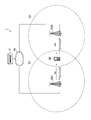
- FIG. 1 is a schematic configuration diagram of a radio communication system 1 in which inter-base station cooperative MIMO communication (multi-cell coordinated transmission / reception or multi-point coordinated transmission / reception (CoMP)) is introduced.
- inter-base station cooperative MIMO communication multi-cell coordinated transmission / reception or multi-point coordinated transmission / reception (CoMP)
- the wireless communication system 1 has a configuration based on LTE-Advanced, which is positioned as a fourth generation (4G) mobile phone system, for example.
- the wireless communication system 1 employs an FDD (Frequency Division Duplex) method as a duplex method.
- FDD Frequency Division Duplex
- the radio communication system 1 includes a radio base station BS1 (first radio base station), a radio base station BS2 (second radio base station), a radio terminal UE, and a control device 11.
- the radio terminal UE is located in an overlapping portion between the cell C1 formed by the radio base station BS1 and the cell C2 formed by the radio base station BS2.
- the radio base station BS1 and the radio base station BS2 may be macro cell base stations or femto cell base stations.
- a femtocell base station is a small radio base station installed mainly indoors.
- the radio base station BS1 and the radio base station BS2 are connected to each other via a backhaul network 10 which is a wired communication network.
- the control device 11 is provided in the backhaul network 10 and controls the radio base station BS1 and the radio base station BS2 via the backhaul network 10.
- the radio base station BS1 and the radio base station BS2 can directly perform communication between base stations without going through the control device 11.
- Closed loop control is introduced in the cooperative MIMO communication between base stations in the wireless communication system 1.
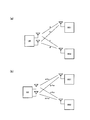
- the radio base station BS1 transmits a radio signal RS1 (first radio signal) to the radio terminal UE in response to feedback from the radio terminal UE.
- the radio base station BS2 transmits the radio signal RS2 (second radio signal) to the radio terminal UE at the same frequency and the same time as the radio signal RS1.
- the radio base station BS1 performs a weighting process (referred to as “precoding”) of the transmission signal in accordance with feedback from the radio terminal UE, and transmits a radio signal RS1 including the weighted transmission signal.
- precoding a weighting process
- the phase and amplitude of the transmission signal are controlled for each transmission antenna of the radio base station BS1.
- the radio base station BS2 performs a weighting process on the transmission signal in accordance with the feedback from the radio terminal UE, and transmits the radio signal RS2 corresponding to the weighted transmission signal.
- the weighting process the phase and amplitude of the transmission signal (radio signal RS2) are controlled for each transmission antenna of the radio base station BS2.
- the transmission signal sequence (also referred to as “stream”) included in the radio signal RS1 transmitted by the radio base station BS1 is the same as the transmission signal sequence included in the radio signal RS2 transmitted by the radio base station BS2. It may be different.
- the reception quality included in the radio signal RS1 and the transmission signal sequence included in the radio signal RS2 are the same (during single stream transmission), the reception quality is improved due to the diversity effect.
- the radio terminal UE is located at the cell edge of the radio base station BS1 and the radio base station BS2, it is preferable to improve the reception quality by single stream transmission.
- the transmission speed included in the radio signal RS1 and the transmission signal sequence included in the radio signal RS2 are different (during multi-stream transmission), the transmission speed is improved.
- the radio base station BS1 or the radio base station BS2 is, for example, a femtocell base station and the radio terminal UE is located near the radio base station BS1 and the radio base station BS2, the transmission rate is increased by multi-stream transmission. It is preferable to improve.
- the time interval at which the radio terminal UE performs feedback to the radio base station BS1 (hereinafter referred to as feedback interval 1) is longer than the time interval at which the radio terminal UE performs feedback to the radio base station BS2 (hereinafter referred to as feedback interval 2).
- the feedback interval 1 is an integral multiple of the feedback interval 2, for example.
- the radio terminal UE performs feedback to the radio base station BS2 in each frame, and performs feedback to the radio base station BS1 once in a plurality of frames.
- the radio terminal UE appropriately omits feedback to the radio base station BS1.
- a radio base station where feedback is appropriately omitted can be selected.
- a radio base station selection method for which feedback is appropriately omitted will be described later.
- the radio terminal UE has propagation path information 1 (first information) corresponding to the propagation path characteristics from the radio base station BS1 to the radio terminal UE in a period in which feedback to the radio base station BS1 is omitted (hereinafter referred to as feedback omission period).
- Feedback based on propagation path information) and propagation path information 2 (second propagation path information) according to propagation path characteristics from the radio base station BS2 to the radio terminal UE is performed to the radio base station BS2.
- the propagation path characteristic means parameters such as an attenuation amount, a phase rotation amount, and a delay amount that are received when a wireless signal passes through the wireless propagation path.
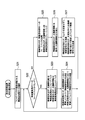
- FIG. 2 is a block diagram showing the configuration of the radio terminal UE.
- the radio terminal UE may have a configuration (such as a power supply unit) that is not illustrated or omitted in the description.
- the radio terminal UE includes a plurality of antennas 111, a transmission / reception unit 120, a control unit 130, and a storage unit 140.
- the radio terminal UE has a plurality of antennas 111, but it is not always necessary to have a plurality of antennas 111, and only one antenna 111 may be provided.
- the transmission / reception unit 120 is configured using, for example, a radio frequency (RF) circuit or a baseband (BB) circuit.
- the control unit 130 is configured using, for example, a CPU, and controls various functions provided in the radio terminal UE.
- the storage unit 140 is configured using a memory, for example, and stores various types of information used for controlling the radio terminal UE and the like.
- the transmission / reception unit 120 includes a reception unit 121 and a transmission unit 122.
- the control unit 130 includes a propagation path information generation unit 131 and a normalization unit 132.
- the receiving unit 121 receives the radio signal RS1 from the radio base station BS1 and also receives the radio signal RS2 from the radio base station BS2. Note that, at the time of single stream transmission or the like, the reception unit 121 preferably receives the radio signal RS1 and the radio signal RS2 in the same phase.
- the propagation path information generation unit 131 uses a reference signal (pilot signal) included in the radio signal RS1 received by the reception unit 121 and the like between each transmission antenna of the radio base station BS1 and each reception antenna of the radio terminal UE.
- the process (what is called channel estimation) which calculates the propagation path estimated value (henceforth, propagation path estimated value 1) which shows a propagation path characteristic is performed.
- the propagation path information generation unit 131 uses a reference signal (pilot signal) included in the radio signal RS2 received by the reception unit 121, between each transmission antenna of the radio base station BS2 and each reception antenna of the radio terminal UE.
- a process of calculating a propagation path estimation value (hereinafter, propagation path estimation value 2) indicating the propagation path characteristics is performed.
- the propagation path information generation unit 131 generates propagation path information 1 that is information to be fed back to the radio base station BS1 based on the propagation path estimated value 1.
- the transmission path information 1 is not limited to the case where the propagation path estimation value 1 is used as the propagation path information 1.
- the transmission path information 1 is used for weighting processing (that is, control of at least one of the phase and the amplitude of the radio signal RS1) in the radio base station BS1. It may be an antenna weight 1 or an index indicating the transmission antenna weight 1 (referred to as “PMI (Pre-coding Matrix Index)”).
- the propagation path information generation unit 131 generates propagation path information 2 that is information to be fed back to the radio base station BS2 based on the propagation path estimation value 2.
- the propagation path information 2 is not limited to the case where the propagation path estimated value 2 is used as the propagation path information 2, and the transmission path information 2 is used for weighting processing (that is, control of at least one of the phase and the amplitude of the radio signal RS 2) in the radio base station BS 2. It may be an antenna weight 2 or an index indicating the transmission antenna weight 2.
- the normalization unit 132 normalizes the propagation path information 2 on the basis of the propagation path information 1 in the feedback omission period. Details of the normalization process will be described later.
- the transmission unit 122 transmits feedback to the radio base station BS1 at a feedback interval 1 and transmits feedback to the radio base station BS2 at a feedback interval 2. Further, the transmission unit 122 feeds back the propagation path information 2 normalized by the normalization unit 132 to the radio base station BS2 during the feedback omission period.
- FIG. 3 is a block diagram showing a configuration of the radio base station BS1.
- the radio base station BS1 includes a plurality of antennas 211, a transmission / reception unit 220, a control unit 230, a storage unit 240, and a wired communication unit 250.
- the radio base station BS ⁇ b> 1 has a plurality of antennas 211, but it is not always necessary to have a plurality of antennas 211, and only one antenna 211 may be provided.
- the transmission / reception unit 220 is configured using, for example, an RF circuit, a BB circuit, or the like.
- the control unit 230 is configured using a CPU, for example, and controls various functions provided in the radio base station BS1.
- the storage unit 240 is configured using, for example, a memory, and stores various types of information used for controlling the radio base station BS1.
- the wired communication unit 250 communicates with the radio base station BS2 and the control device 11 via the backhaul network 10.
- the transmission / reception unit 220 includes a reception unit 221 and a transmission unit 222.
- the control unit 230 includes a weight control unit 231.
- the reception unit 221 receives the fed back propagation path information 1.
- the weight control unit 231 controls the transmission antenna weight 1 used for transmission of the radio signal RS1.
- the weight control unit 231 updates the transmission antenna weight 1 according to the propagation path information 1 and notifies the transmission unit 222 of the updated transmission antenna weight 1.
- the weight control unit 231 notifies the transmitting unit 222 of the transmitting antenna weight 1 that has been used without updating the transmitting antenna weight 1. To do.
- the transmission unit 222 weights (precodes) the transmission signal using the transmission antenna weight 1 notified from the weight control unit 231 and transmits the radio signal RS1 including the weighted transmission signal.
- FIG. 4 is a block diagram showing the configuration of the radio base station BS2.
- the radio base station BS2 includes a plurality of antennas 311, a transmission / reception unit 320, a control unit 330, a storage unit 340, and a wired communication unit 350.
- the radio base station BS ⁇ b> 2 has a plurality of antennas 211, but it is not always necessary to have a plurality of antennas 211, and only one antenna 211 may be provided.
- the transmission / reception unit 320 is configured using, for example, an RF circuit or a BB circuit.
- the control unit 330 is configured using, for example, a CPU, and controls various functions provided in the radio base station BS2.
- the storage unit 340 is configured using, for example, a memory, and stores various types of information used for controlling the radio base station BS2.
- the wired communication unit 350 communicates with the radio base station BS1 and the control device 11 via the backhaul network 10.
- the transmission / reception unit 320 includes a reception unit 321 and a transmission unit 322.
- the control unit 330 includes a weight control unit 331.
- the receiving unit 321 receives the propagation path information 2 fed back from the radio terminal UE.
- the propagation path information 2 received by the receiving unit 321 may be normalized or not normalized.
- the weight control unit 331 controls the transmission antenna weight 2 used for transmission of the radio signal RS2.
- the weight control unit 331 updates the transmission antenna weight 2 according to the propagation path information 2 received by the reception unit 321, and notifies the transmission unit 322 of the updated transmission antenna weight 2.
- the transmission unit 322 weights (precodes) the transmission signal using the transmission antenna weight 2 notified from the weight control unit 331, and transmits the radio signal RS2 including the weighted transmission signal.
- the propagation path estimation value has a value for each antenna (for each combination of transmission and reception antennas), but if the relative relationship is maintained, even if the value itself is changed, it is processed appropriately on the receiving side (signal separation, etc.) it can.
- the propagation path estimated value 1 (a, b) and the propagation path estimated value 2 (c, d) shown in FIG. 5 (a) as shown in FIG. 5 (b), (a x e, b x ⁇ e, c x e, d x e)
- the phase relationship between the propagation path estimation value 1 and the propagation path estimation value 2 is maintained. Since the same phase relationship is maintained, there is no particular problem.
- the propagation path estimated value 1 (a) and the propagation path estimated value 2 (b, c, d), which require feedback, are shown in FIG. 6 (b).
- the channel estimation value 2 is divided by the channel estimation value 1.
- the value 1 can be virtually always fixed to (1), and feedback to the radio base station BS1 can be made unnecessary.
- normalization is performed by dividing the channel estimation value 2 by the channel estimation value 1, but any other calculation method can be used as long as the relative relationship between the channel estimation value 1 and the channel estimation value 2 is maintained.
- normalization may be performed by subtracting the propagation path estimated value 1 from the propagation path estimated value 2.
- the propagation path information 1 is the transmission antenna weight 1 or its index and the propagation path information 2 is the transmission antenna weight 2 or its index
- a candidate for the transmission antenna weight 2 is selected from the “codebook”), and the selected transmission antenna weight 2 or its index is fed back to the radio base station BS2.
- the following method may be employed as a method for selecting an optimum PMI from a list (code book) of an index (herein referred to as “PMI”) of the transmission antenna weight 2.
- PMI an index
- the reception SNR when the PMI in the list is used is calculated for each PMI, and the maximum reception among the calculated reception SNRs.
- the PMI corresponding to the SNR is selected as the optimum PMI.
- Such a method is effective when the PMI in the list is small.
- the normalization unit 132 maximizes the reception SNR based on the propagation path estimated value 1 and the propagation path estimated value 2 under the assumption that the radio base station BS1 performs fixed transmission.
- the PMI is selected (searched) as a PMI to be fed back to the radio base station BS2.
- the radio base station BS1 has one transmission antenna, but the same processing can be applied to a case where there are a plurality of transmission antennas.
- the base station selection process may be executed by any of the radio terminal UE, the radio base station BS1, the radio base station BS2, and the control device 11.
- any of the following selection methods 1 to 5 can be used.
- the selection methods 1 to 5 are not limited to be used in a fixed manner, and the selection methods 1 to 5 are appropriately switched depending on the situation of the radio terminal UE, the radio base station BS1, and the radio base station BS2. May be.
- Selection method 1 a radio base station located far from the radio terminal UE is selected as the radio base station BS1, and a radio base station located close to the radio terminal UE is selected as the radio base station BS2. Thereby, the radio terminal UE always performs feedback to the radio base station BS2 located close to the radio terminal UE, and appropriately omits feedback to the radio base station BS1 located far from the radio terminal UE. The transmission power for feedback can be reduced, and the amount of interference can be reduced.
- the selection method 1 is preferable when the battery level of the radio terminal UE is low.
- the selection method 1 information on the distance between the radio terminal UE and the radio base station BS1 and the distance between the radio terminal UE and the radio base station BS2 are required, but the information is provided in the radio terminal UE.
- Distance information can be obtained using GPS or the like.
- Selection method 2 a radio base station with high processing performance (specifically, a macro cell base station) is selected as the radio base station BS1, and a radio base station with low processing performance (specifically, a femtocell base station) Is selected as the radio base station BS2.
- the radio terminal UE since the femtocell base station exists near the radio terminal UE, the radio terminal UE always performs feedback to the radio base station BS2 (femtocell base station) located nearby from the radio terminal UE. Feedback to the radio base station BS1 (macro cell base station) located far from the UE is omitted as appropriate. For example, when the radio terminal UE is not provided with GPS or the like, the selection method 2 is effective.
- Selection method 3 a radio base station with low processing performance (specifically, a femtocell base station) is selected as the radio base station BS1, and a radio base station with high processing performance (specifically, a macrocell base station) is selected. Is selected as the radio base station BS2. Selection method 3 can be achieved because a radio base station with low processing performance performs constant transmission with fixed weight and a radio base station with high processing performance performs multi-antenna multi-stream transmission to obtain a high transmission rate. Is effective when a high transmission rate is required or when the battery of the radio terminal UE is high.
- Selection method 4 In the selection method 4, a radio base station having a small propagation path fluctuation with the radio terminal UE is selected as the radio base station BS1, and a radio base station having a large propagation path fluctuation with the radio terminal UE is selected as the radio base station BS2. Choose as. This is because the radio base station BS1 performs constant transmission with a fixed weight, and thus it is preferable that the propagation path fluctuation is small. Selection method 4 is effective when there is a large difference in propagation path fluctuation with each radio base station.
- Selection method 5 In the selection method 5, a radio base station having a large propagation path loss with the radio terminal UE is selected as the radio base station BS1, and a radio base station having a small propagation path loss with the radio terminal UE is selected as the radio base station BS2. Choose as.
- the propagation path loss is calculated as the difference between the transmission power at the radio base station and the reception power at the radio terminal UE, and reflects the distance between the terminal and the base station. For this reason, the radio terminal UE can always perform feedback to the radio base station BS2 located close to the radio terminal UE and appropriately omit feedback to the radio base station BS1 located far from the radio terminal UE. Since the propagation path loss is used for other purposes such as transmission power control and can be easily obtained, the selection method 5 can effectively utilize the existing system configuration.
- step S11 the radio base station BS1 from which feedback is appropriately omitted is selected by the process described in the above (3) base station selection process.
- an apparatus other than the radio terminal UE radio base station BS1, radio base station BS2, control apparatus 11
- the apparatus propagates to the radio base station BS1.
- the radio terminal UE is instructed to appropriately omit the feedback of the route information 1.
- step S13 the transmission unit 122 of the radio terminal UE feeds back the propagation path information 1 to the radio base station BS1, and the propagation path information 2 To the radio base station BS2.
- the receiving unit 221 of the radio base station BS1 receives the propagation path information 1.
- the receiving unit 321 of the radio base station BS2 receives the propagation path information 2.
- step S14 the transmitter 222 of the radio base station BS1 transmits the radio signal RS1 to the radio terminal UE using the transmission antenna weight 1 updated by the weight controller 231 according to the propagation path information 1 received by the receiver 221.
- the transmission unit 322 of the radio base station BS2 transmits the radio signal RS2 to the radio terminal UE using the transmission antenna weight 2 updated by the weight control unit 331 according to the propagation path information 2 received by the reception unit 321.
- step S15 the normalization unit 132 of the radio terminal UE performs the process described in the above (2) normalization process.
- the propagation path information 2 is normalized with reference to the propagation path information 1.
- step S16 the transmission unit 122 of the radio terminal UE omits feedback of the propagation path information 1 to the radio base station BS1, and feeds back the propagation path information 2 normalized by the normalization unit 132 to the radio base station BS2. To do.
- the receiving unit 321 of the radio base station BS2 receives the normalized propagation path information 2.
- the weight control unit 331 of the radio base station BS2 notifies the transmission unit 322 of the transmission antenna weight 2 updated according to the propagation path information 2 received by the reception unit 321.
- step S17 the transmission unit 322 of the radio base station BS2 weights the transmission signal using the updated transmission antenna weight 2 notified from the weight control unit 331, and transmits the radio signal RS2 including the weighted transmission signal. To do. Further, the transmission unit 222 of the radio base station BS1 weights the transmission signal using the transmission antenna weight 1 that has not been updated, and transmits the radio signal RS1 including the weighted transmission signal.
- the radio terminal UE appropriately omits feedback to the radio base station BS1. Thereby, the overhead accompanying feedback can be reduced. That is, in the feedback omission period, the radio terminal UE only needs to set a control channel for feedback with the radio base station BS2, so that the radio resource consumption in the uplink is reduced.
- the radio terminal UE normalizes the propagation path information 2 on the basis of the propagation path information 1 and feeds back the normalized propagation path information 2 to the radio base station BS2 during the feedback omitted period.
- the radio base station BS2 since the radio base station BS2 transmits the radio signal RS2 according to the propagation path information 2 in which the relative relationship with the propagation path information 1 is maintained, the inter-base station cooperative MIMO communication is normally performed even during the feedback omitted period. Can function.
- the radio terminal UE normalizes the propagation path information.
- the radio base station BS2 normalizes the propagation path information.
- (1) the configuration of the wireless communication system, (2) the operation of the wireless communication system, and (3) the effects of the second embodiment will be described. However, differences from the first embodiment will be described.
- FIG. 8 is a block diagram illustrating a configuration of a radio terminal UE according to the second embodiment.
- FIG. 9 is a block diagram showing a configuration of the radio base station BS2 according to the second embodiment.
- the radio terminal UE does not have the normalization unit 132 described in the first embodiment.
- the radio base station BS2 has a normalization unit 332 having the same function as the normalization unit 132 described in the first embodiment.
- the radio base station BS2 has a normalization unit 332 having the same function as the normalization unit 132 described in the first embodiment.
- the normalization unit 332 has the same function as the normalization unit 132 described in the first embodiment.
- it is the same as that of 1st Embodiment.
- step S25 the propagation path information generation unit 131 of the radio terminal UE generates propagation path information 1 and propagation path information 2. Then, the transmitter 122 of the radio terminal UE omits the feedback of the propagation path information 1 to the radio base station BS1, and transmits the propagation path information 1 and the propagation path information 2 generated by the propagation path information generation section 131 to the radio base station. Feedback to station BS2. The receiving unit 321 of the radio base station BS2 receives the fed back propagation path information 1 and propagation path information 2.
- step S26 the normalization unit 332 of the radio base station BS2 normalizes the propagation path information 2 based on the propagation path information 1 by the same process as that described in (2) normalization process in the first embodiment. To do.
- the weight control unit 331 of the radio base station BS2 notifies the transmission unit 322 of the transmission antenna weight 2 updated according to the propagation path information 2 normalized by the normalization unit 332.
- step S27 the transmission unit 322 of the radio base station BS2 weights the transmission signal using the updated transmission antenna weight 2 notified from the weight control unit 331, and transmits the radio signal RS2 including the weighted transmission signal. To do. Also, the transmitter 222 of the radio base station BS1 weights the transmission signal using the transmission antenna weight 1 that has not been updated, and transmits the radio signal RS1 including the weighted transmission signal at a constant rate.
- the radio terminal UE omits feedback to the radio base station BS1 during the feedback omission period, and transmits the propagation path information 1 and the propagation path information 2 to the radio base station BS2.
- the radio base station BS2 normalizes the propagation path information 2 fed back from the radio terminal UE with reference to the propagation path information 1 fed back from the radio terminal UE, and responds to the normalized propagation path information 2 To update the transmission antenna weight 2.
- the radio terminal UE since the radio terminal UE only needs to set a control channel for feedback with the radio base station BS2 during the feedback omission period, radio resource consumption in the uplink is reduced. Further, since the radio base station BS2 transmits the radio signal RS2 according to the propagation path information 2 in which the relative relationship with the propagation path information 1 is maintained, the inter-base station cooperative MIMO communication is normally performed even during the feedback omitted period. Can function.
- the feedback channel information is a channel estimation value, a transmission antenna weight, or an index thereof.
- the present invention is not limited to this, and a future channel is calculated based on the channel estimation value. It may be a predicted channel value indicating the characteristic.
- the propagation path information 1 and the propagation path information 2 are fed back to the radio base station BS2, the propagation path information 1 and the propagation path information 2 are transferred from the radio base station BS2 to the radio base station BS1. It is also possible to switch the radio base station from which the feedback is appropriately omitted after the transfer from the radio base station BS1 to the radio base station BS2.
- the wireless terminal As described above, according to the wireless communication system, the wireless terminal, and the wireless communication method according to the present invention, it is possible to reduce overhead due to feedback while allowing the inter-base station cooperative MIMO communication to function normally, so that mobile communication, etc. Useful in wireless communications.
Landscapes
- Engineering & Computer Science (AREA)
- Computer Networks & Wireless Communication (AREA)
- Signal Processing (AREA)
- Mobile Radio Communication Systems (AREA)
- Physics & Mathematics (AREA)
- Mathematical Physics (AREA)
- Radio Transmission System (AREA)
Abstract
Description
第1実施形態においては、(1)無線通信システムの構成、(2)正規化処理、(3)基地局選択処理、(4)無線通信システムの動作、(5)第1実施形態の効果について説明する。
まず、(1.1)全体概略構成、(1.2)無線端末UEの構成、(1.3)無線基地局BS1の構成、(1.4)無線基地局BS2の構成について説明する。
図1は、基地局間協調MIMO通信(マルチセル協調送受信又は複数地点協調送受信(CoMP))が導入された無線通信システム1の概略構成図である。
図2は、無線端末UEの構成を示すブロック図である。
図3は、無線基地局BS1の構成を示すブロック図である。
図4は、無線基地局BS2の構成を示すブロック図である。
次に、図5及び図6を参照して、正規化部132によって実行される正規化処理について説明する。まず、伝播路情報1が伝搬路推定値1であり、伝播路情報2が伝搬路推定値2である場合について説明する。
次に、フィードバックが適宜省略される無線基地局(無線基地局BS1)を選択する処理である基地局選択処理について説明する。基地局選択処理は、無線端末UE、無線基地局BS1、無線基地局BS2、及び制御装置11の何れが実行してもよい。
選択方法1においては、無線端末UEから遠くに位置する無線基地局を無線基地局BS1として選択し、無線端末UEから近くに位置する無線基地局を無線基地局BS2として選択する。これにより、無線端末UEは、無線端末UEから近くに位置する無線基地局BS2へのフィードバックを常時行い、無線端末UEから遠くに位置する無線基地局BS1へのフィードバックを適宜省略することになり、フィードバック用の送信電力を低減でき、与干渉量を低減できる。無線端末UEの電池残量が少ない場合等には選択方法1が好ましい。なお、選択方法1においては、無線端末UEと無線基地局BS1との間の距離、及び無線端末UEと無線基地局BS2との間の距離の情報が必要となるが、無線端末UEに設けられるGPS等を利用して距離の情報を得ることができる。
選択方法2においては、処理性能が高い無線基地局(具体的には、マクロセル基地局)を無線基地局BS1として選択し、処理性能が低い無線基地局(具体的には、フェムトセル基地局)を無線基地局BS2として選択する。通常、フェムトセル基地局は、無線端末UEの近くに存在するため、無線端末UEは、無線端末UEから近くに位置する無線基地局BS2(フェムトセル基地局)へのフィードバックを常時行い、無線端末UEから遠くに位置する無線基地局BS1(マクロセル基地局)へのフィードバックを適宜省略する。例えば無線端末UEにGPS等が設けられていない場合には、選択方法2が有効である。
選択方法3においては、処理性能が低い無線基地局(具体的には、フェムトセル基地局)を無線基地局BS1として選択し、処理性能が高い無線基地局(具体的には、マクロセル基地局)を無線基地局BS2として選択する。処理性能が低い無線基地局にウェイト固定の一定送信を実行させ、処理性能が高い無線基地局にマルチアンテナのマルチストリーム送信をさせることで、高速な伝送速度を得ることができるため、選択方法3は、高速な伝送速度が要求される場合や、無線端末UEの電池残量が多い場合に有効である。
選択方法4においては、無線端末UEとの間の伝搬路変動が小さい無線基地局を無線基地局BS1として選択し、無線端末UEとの間の伝搬路変動が大きい無線基地局を無線基地局BS2として選択する。これは、無線基地局BS1はウェイト固定の一定送信となるため、伝搬路変動が小さいことが好ましいからである。各無線基地局との間の伝搬路変動に大きな差がある場合には、選択方法4が有効である。
選択方法5においては、無線端末UEとの間の伝搬路損失が大きい無線基地局を無線基地局BS1として選択し、無線端末UEとの間の伝搬路損失が小さい無線基地局を無線基地局BS2として選択する。伝搬路損失は、無線基地局における送信電力と、無線端末UEにおける受信電力との差として計算され、端末・基地局間の距離を反映している。このため、無線端末UEは、無線端末UEから近くに位置する無線基地局BS2へのフィードバックを常時行い、無線端末UEから遠くに位置する無線基地局BS1へのフィードバックを適宜省略することができる。伝搬路損失は、送信電力制御等の他の用途に使用され、容易に得ることができるため、選択方法5によれば既存のシステム構成を有効に活用できる。
次に、図7を参照して、第1実施形態に係る無線通信システム1の動作について説明する。
無線端末UEは、無線基地局BS1へのフィードバックを適宜省略する。これにより、フィードバックに伴うオーバヘッドを低減できる。すなわち、フィードバック省略期間においては、無線端末UEが無線基地局BS2との間にのみフィードバック用の制御チャネルを設定すればよいため、アップリンクにおける無線リソースの消費量が削減される。
第1実施形態においては無線端末UEが伝搬路情報の正規化を行っていたが、第2実施形態では、無線基地局BS2が伝搬路情報の正規化を行う。以下において、(1)無線通信システムの構成、(2)無線通信システムの動作、(3)第2実施形態の効果について説明する。ただし、第1実施形態と異なる点を説明する。
図8は、第2実施形態に係る無線端末UEの構成を示すブロック図である。図9は、第2実施形態に係る無線基地局BS2の構成を示すブロック図である。
次に、図10を参照して、第2実施形態に係る無線通信システム1の動作について説明する。ただし、ステップS21~S24の処理は第1実施形態と同様であるため、ステップS25~S27の処理について説明する。
第2実施形態では、フィードバック省略期間において無線端末UEは、無線基地局BS1へのフィードバックを省略するとともに、伝播路情報1及び伝播路情報2を無線基地局BS2にフィードバックし、無線基地局BS2は、無線端末UEからフィードバックされた伝播路情報1を基準として、無線端末UEからフィードバックされた伝播路情報2を正規化し、正規化された伝播路情報2に応じて送信アンテナウェイト2を更新する。
上記のように、本発明は実施形態によって記載したが、この開示の一部をなす論述及び図面はこの発明を限定するものであると理解すべきではない。この開示から当業者には様々な代替実施形態、実施例及び運用技術が明らかとなる。
Claims (15)
- 無線端末と、
前記無線端末からのフィードバックに応じて第1無線信号を前記無線端末に送信する第1無線基地局と、
前記無線端末からのフィードバックに応じて、前記第1無線信号と同一の周波数及び同一の時間で第2無線信号を前記無線端末に送信する第2無線基地局と
を有し、
前記無線端末が前記第1無線基地局へのフィードバックを行う時間間隔は、前記無線端末が前記第2無線基地局へのフィードバックを行う時間間隔よりも長い無線通信システム。 - 前記第1無線基地局は、前記無線端末からのフィードバックに応じて、前記第1無線信号の位相又は振幅の少なくとも一方の制御に用いられる第1送信アンテナウェイトを更新し、
前記第2無線基地局は、前記無線端末からのフィードバックに応じて、前記第2無線信号の位相又は振幅の少なくとも一方の制御に用いられる第2送信アンテナウェイトを更新し、
前記第1無線基地局が前記第1送信アンテナウェイトを更新する時間間隔は、前記第2無線基地局が前記第2送信アンテナウェイトを更新する時間間隔よりも長い請求項1に記載の無線通信システム。 - 前記無線端末は、前記第1無線基地局へのフィードバックを省略している期間において、前記第1無線基地局から前記無線端末までの伝搬路特性に応じた第1伝搬路情報と、前記第2無線基地局から前記無線端末までの伝搬路特性に応じた第2伝搬路情報とに基づくフィードバックを前記第2無線基地局に対して行う請求項1に記載の無線通信システム。
- 前記無線端末は、前記第1無線基地局へのフィードバックを省略している期間において、前記第1伝搬路情報を基準として前記第2伝搬路情報を正規化し、前記正規化された第2伝搬路情報を前記第2無線基地局にフィードバックする請求項3に記載の無線通信システム。
- 前記無線端末は、前記第1無線基地局へのフィードバックを省略している期間において、前記第1伝搬路情報及び前記第2伝搬路情報を前記第2無線基地局にフィードバックし、
前記第2無線基地局は、前記無線端末からフィードバックされた前記第1伝搬路情報を基準として、前記無線端末からフィードバックされた前記第2伝搬路情報を正規化し、前記正規化された第2伝搬路情報に応じて前記第2無線信号を送信する請求項3に記載の無線通信システム。 - 前記第1伝搬路情報は、前記第1無線基地局の各送信アンテナと前記無線端末の各受信アンテナとの間の伝搬路特性を示す情報であり、
前記第2伝搬路情報は、前記第2無線基地局の各送信アンテナと前記無線端末の各受信アンテナとの間の伝搬路特性を示す情報である請求項3に記載の無線通信システム。 - 前記第1伝搬路情報は、前記第1無線信号の位相又は振幅の少なくとも一方の制御に用いられる第1送信アンテナウェイト、又は、前記第1送信アンテナウェイトを示すインデックスであり、
前記第2伝搬路情報は、前記第2無線信号の位相又は振幅の少なくとも一方の制御に用いられる第2送信アンテナウェイト、又は、前記第2送信アンテナウェイトを示すインデックスである請求項3に記載の無線通信システム。 - 前記第1無線基地局は、前記第2無線基地局よりも、前記無線端末から遠くに位置する無線基地局である請求項1に記載の無線通信システム。
- 前記第1無線基地局は、前記第2無線基地局よりも処理性能が高い無線基地局である請求項1に記載の無線通信システム。
- 前記第1無線基地局は、前記第2無線基地局よりも処理性能が低い無線基地局である請求項1に記載の無線通信システム。
- 前記第1無線基地局は、前記第2無線基地局よりも、前記無線端末との間の伝搬路変動が小さい無線基地局である請求項1に記載の無線通信システム。
- 前記第1無線基地局は、前記第2無線基地局よりも、前記無線端末との間の伝搬路損失が大きい無線基地局である請求項1に記載の無線通信システム。
- 第1無線基地局から第1無線信号を受信し、前記第1無線信号と同一の周波数及び同一の時間で第2無線信号を第2無線基地局から受信する受信部と、
前記第1無線基地局及び前記第2無線基地局へのフィードバックを送信する送信部と
を有し、
前記送信部が前記第1無線基地局へのフィードバックを行う時間間隔は、前記送信部が前記第2無線基地局へのフィードバックを行う時間間隔よりも長い無線端末。 - 無線端末からのフィードバックに応じて第1無線信号を前記無線端末に送信する第1無線基地局と、
前記無線端末からのフィードバックに応じて、前記第1無線信号と同一の周波数及び同一の時間で第2無線信号を前記無線端末に送信する第2無線基地局と
を有し、
前記第1無線基地局又は前記第2無線基地局は、前記第1無線基地局へのフィードバックを行う時間間隔を、前記第2無線基地局へのフィードバックを行う時間間隔よりも長くするよう前記無線端末に指示する無線通信システム。 - 無線端末からのフィードバックに応じて第1無線基地局が第1無線信号を前記無線端末に送信するステップと、
前記無線端末からのフィードバックに応じて、前記第1無線信号と同一の周波数及び同一の時間で第2無線基地局が第2無線信号を前記無線端末に送信するステップと
を有し、
前記無線端末が前記第1無線基地局へのフィードバックを行う時間間隔は、前記無線端末が前記第2無線基地局へのフィードバックを行う時間間隔よりも長い無線通信方法。
Priority Applications (4)
| Application Number | Priority Date | Filing Date | Title |
|---|---|---|---|
| US13/321,946 US8818447B2 (en) | 2009-05-27 | 2010-05-27 | Radio communication system, radio terminal, and radio communication method |
| EP10780620.0A EP2437535A4 (en) | 2009-05-27 | 2010-05-27 | WIRELESS COMMUNICATION SYSTEM, WIRELESS TERMINAL, AND WIRELESS COMMUNICATION METHOD |
| CN2010800236495A CN102450049A (zh) | 2009-05-27 | 2010-05-27 | 无线通信系统、无线终端和无线通信方法 |
| US14/333,383 US9191085B2 (en) | 2009-05-27 | 2014-07-16 | Radio communication system, radio terminal, and radio communication method |
Applications Claiming Priority (2)
| Application Number | Priority Date | Filing Date | Title |
|---|---|---|---|
| JP2009128169A JP5319398B2 (ja) | 2009-05-27 | 2009-05-27 | 無線通信システム、無線端末及び無線通信方法 |
| JP2009-128169 | 2009-05-27 |
Related Child Applications (2)
| Application Number | Title | Priority Date | Filing Date |
|---|---|---|---|
| US13/321,946 A-371-Of-International US8818447B2 (en) | 2009-05-27 | 2010-05-27 | Radio communication system, radio terminal, and radio communication method |
| US14/333,383 Continuation US9191085B2 (en) | 2009-05-27 | 2014-07-16 | Radio communication system, radio terminal, and radio communication method |
Publications (1)
| Publication Number | Publication Date |
|---|---|
| WO2010137666A1 true WO2010137666A1 (ja) | 2010-12-02 |
Family
ID=43222771
Family Applications (1)
| Application Number | Title | Priority Date | Filing Date |
|---|---|---|---|
| PCT/JP2010/059042 WO2010137666A1 (ja) | 2009-05-27 | 2010-05-27 | 無線通信システム、無線端末及び無線通信方法 |
Country Status (6)
| Country | Link |
|---|---|
| US (2) | US8818447B2 (ja) |
| EP (1) | EP2437535A4 (ja) |
| JP (1) | JP5319398B2 (ja) |
| KR (1) | KR20120025500A (ja) |
| CN (1) | CN102450049A (ja) |
| WO (1) | WO2010137666A1 (ja) |
Cited By (2)
| Publication number | Priority date | Publication date | Assignee | Title |
|---|---|---|---|---|
| CN103348616A (zh) * | 2011-02-10 | 2013-10-09 | 索尼公司 | 终端设备、反馈控制方法、基站、配对控制方法、程序和无线通信系统 |
| CN109845170A (zh) * | 2016-08-11 | 2019-06-04 | 弗劳恩霍夫应用研究促进协会 | 利用缩短帧结构的探测反馈 |
Families Citing this family (7)
| Publication number | Priority date | Publication date | Assignee | Title |
|---|---|---|---|---|
| WO2011114079A1 (en) * | 2010-03-19 | 2011-09-22 | Fujitsu Limited | Cell selection for multi-cell mimo transmission |
| JP5720284B2 (ja) * | 2011-02-10 | 2015-05-20 | ソニー株式会社 | 端末装置、フィードバック制御方法、基地局、ペアリング制御方法、プログラム及び無線通信システム |
| JP5703057B2 (ja) * | 2011-02-17 | 2015-04-15 | シャープ株式会社 | 通信システム、基地局装置、端末装置 |
| KR101407103B1 (ko) * | 2012-12-04 | 2014-06-13 | 서강대학교산학협력단 | 협력적 전송 방법 |
| JP6108082B2 (ja) * | 2013-03-01 | 2017-04-05 | パナソニックIpマネジメント株式会社 | 通信端末装置、基地局装置及び送信方法 |
| KR20180009776A (ko) * | 2015-06-23 | 2018-01-29 | 후지쯔 가부시끼가이샤 | 무선 통신 제어 방법, 무선 통신 시스템, 수신 장치 및 송신 장치 |
| JP2022186062A (ja) * | 2021-06-04 | 2022-12-15 | 日本電気株式会社 | ネットワーク同期システム、およびネットワークシステムの同期方法 |
Citations (3)
| Publication number | Priority date | Publication date | Assignee | Title |
|---|---|---|---|---|
| JP2008523665A (ja) | 2004-12-07 | 2008-07-03 | アダプティクス、インク | マルチセル無線ネットワークにおける協調的mimo |
| JP2009128169A (ja) | 2007-11-22 | 2009-06-11 | Canon Inc | 標的物質の検出方法、検出カートリッジ、検出キット |
| JP2010045783A (ja) * | 2008-08-11 | 2010-02-25 | Ntt Docomo Inc | マルチセル協調送信方法 |
Family Cites Families (5)
| Publication number | Priority date | Publication date | Assignee | Title |
|---|---|---|---|---|
| US8396153B1 (en) | 2004-12-07 | 2013-03-12 | Adaptix, Inc. | Cooperative MIMO in multicell wireless networks |
| KR101023274B1 (ko) * | 2005-04-20 | 2011-03-18 | 더 보드 오브 리전츠 오브 더 유니버시티 오브 텍사스 시스템 | 셀룰러 통신을 위한 채널 정보 피드백 시스템 및 방법 |
| KR101387532B1 (ko) * | 2007-12-26 | 2014-04-21 | 엘지전자 주식회사 | 협력적 mimo 수행을 위한 피드백 정보 전송방법 |
| CN107846372B (zh) * | 2011-04-01 | 2021-02-09 | 英特尔公司 | 在载波聚合通信系统中执行多定时超前调整 |
| US9363002B2 (en) * | 2012-03-08 | 2016-06-07 | Telefonaktiebolaget Lm Ericsson (Publ) | Precoding with partially stale feedback |
-
2009
- 2009-05-27 JP JP2009128169A patent/JP5319398B2/ja active Active
-
2010
- 2010-05-27 EP EP10780620.0A patent/EP2437535A4/en not_active Withdrawn
- 2010-05-27 US US13/321,946 patent/US8818447B2/en not_active Expired - Fee Related
- 2010-05-27 CN CN2010800236495A patent/CN102450049A/zh active Pending
- 2010-05-27 KR KR1020117028954A patent/KR20120025500A/ko active IP Right Grant
- 2010-05-27 WO PCT/JP2010/059042 patent/WO2010137666A1/ja active Application Filing
-
2014
- 2014-07-16 US US14/333,383 patent/US9191085B2/en active Active
Patent Citations (3)
| Publication number | Priority date | Publication date | Assignee | Title |
|---|---|---|---|---|
| JP2008523665A (ja) | 2004-12-07 | 2008-07-03 | アダプティクス、インク | マルチセル無線ネットワークにおける協調的mimo |
| JP2009128169A (ja) | 2007-11-22 | 2009-06-11 | Canon Inc | 標的物質の検出方法、検出カートリッジ、検出キット |
| JP2010045783A (ja) * | 2008-08-11 | 2010-02-25 | Ntt Docomo Inc | マルチセル協調送信方法 |
Non-Patent Citations (4)
| Title |
|---|
| "3GPP TSG RAN WG1 Meeting #56bis, Rl- 091193, 2009.03.20", article LG ELECTRONICS: "UE Measurement and Feedback for DL CoMP", XP050338810 * |
| "3GPP TSG RAN WG1 Meeting #57, R1-092221, 2009.05.08", article MOTOROLA: "Spatial Correlation Feedback to Support LTE-A MU-MIMO and CoMP: System Operation and Performance Results", XP050339645 * |
| MOTOHIRO TANNO ET AL.: "Coordinated Multiple- Point Transmission/Reception and Relay Techniques for LTE-Advanced", NEN THE INSTITUTE OF ELECTRONICS, INFORMATION AND COMMUNICATION ENGINEERS SOGO TAIKAI KOEN RONBUNSHU BP-2-4, 4 March 2009 (2009-03-04), XP008154539 * |
| See also references of EP2437535A4 * |
Cited By (7)
| Publication number | Priority date | Publication date | Assignee | Title |
|---|---|---|---|---|
| CN103348616A (zh) * | 2011-02-10 | 2013-10-09 | 索尼公司 | 终端设备、反馈控制方法、基站、配对控制方法、程序和无线通信系统 |
| CN103348616B (zh) * | 2011-02-10 | 2016-03-30 | 索尼公司 | 终端设备、反馈控制方法、基站、配对控制方法和无线通信系统 |
| US9331766B2 (en) | 2011-02-10 | 2016-05-03 | Sony Corporation | Terminal apparatus, feedback control method, base station, pairing control method, program, and wireless communication system |
| US9843415B2 (en) | 2011-02-10 | 2017-12-12 | Sony Corporation | Terminal apparatus, feedback control method, base station, pairing control method, program, and wireless communication system |
| CN109845170A (zh) * | 2016-08-11 | 2019-06-04 | 弗劳恩霍夫应用研究促进协会 | 利用缩短帧结构的探测反馈 |
| CN109845170B (zh) * | 2016-08-11 | 2022-11-25 | 弗劳恩霍夫应用研究促进协会 | 利用缩短帧结构的探测反馈 |
| US11848877B2 (en) | 2016-08-11 | 2023-12-19 | Fraunhofer-Gesellschaft Zur Foerderung Der Angewandten Forschung E.V. | Sounding feedback utilizing shortened frame structures |
Also Published As
| Publication number | Publication date |
|---|---|
| CN102450049A (zh) | 2012-05-09 |
| US20120071199A1 (en) | 2012-03-22 |
| US20140328424A1 (en) | 2014-11-06 |
| EP2437535A1 (en) | 2012-04-04 |
| JP5319398B2 (ja) | 2013-10-16 |
| US8818447B2 (en) | 2014-08-26 |
| JP2010278674A (ja) | 2010-12-09 |
| EP2437535A4 (en) | 2014-12-03 |
| KR20120025500A (ko) | 2012-03-15 |
| US9191085B2 (en) | 2015-11-17 |
Similar Documents
| Publication | Publication Date | Title |
|---|---|---|
| JP5319398B2 (ja) | 無線通信システム、無線端末及び無線通信方法 | |
| JP5917469B2 (ja) | Sdmaビームによる直交リソースの再使用 | |
| KR101241910B1 (ko) | 다중 셀 환경에서 사운딩 채널을 이용한 협력적 mimo 기법 | |
| JP5133413B2 (ja) | 無線通信装置および無線通信方法 | |
| JP6156516B2 (ja) | 無線通信方法、無線通信システム及び基地局 | |
| US10523298B2 (en) | Method for controlling wireless communication, wireless communication system, reception device, and transmission device | |
| US11923933B2 (en) | Operating communication devices | |
| JP2010171734A (ja) | 無線基地局および無線通信方法 | |
| US8615049B2 (en) | Method and apparatus for controlling co-channel interference in a wireless communication system | |
| Ramprashad et al. | Cooperative cellular networks using multi-user MIMO: trade-offs, overheads, and interference control across architectures | |
| EP3501115A1 (en) | Radio node and method therein for determining precoders | |
| US20160043839A1 (en) | Communication system, user terminal, and serving base station | |
| JP5315130B2 (ja) | 無線通信システム、無線端末及び無線通信方法 | |
| JP5244630B2 (ja) | 無線通信システム、無線端末、制御装置、及び無線通信方法 | |
| US11223412B2 (en) | Radio node and methods in a wireless communications network | |
| JP5449602B2 (ja) | 無線通信システム及び無線端末 | |
| Ayanampudi et al. | Performance analysis of heterogeneous cloud-radio access networks: A user-centric approach with network scalability | |
| WO2023198805A1 (en) | Nodes and methods for transmission of downlink radio signals in a distributed multiple input multiple output system | |
| JP2013153529A (ja) | 無線端末およびプロセッサ |
Legal Events
| Date | Code | Title | Description |
|---|---|---|---|
| WWE | Wipo information: entry into national phase |
Ref document number: 201080023649.5 Country of ref document: CN |
|
| 121 | Ep: the epo has been informed by wipo that ep was designated in this application |
Ref document number: 10780620 Country of ref document: EP Kind code of ref document: A1 |
|
| WWE | Wipo information: entry into national phase |
Ref document number: 13321946 Country of ref document: US |
|
| NENP | Non-entry into the national phase |
Ref country code: DE |
|
| ENP | Entry into the national phase |
Ref document number: 20117028954 Country of ref document: KR Kind code of ref document: A |
|
| WWE | Wipo information: entry into national phase |
Ref document number: 2010780620 Country of ref document: EP |