US20060038081A1 - Electric dipole spacecraft - Google Patents
Electric dipole spacecraft Download PDFInfo
- Publication number
- US20060038081A1 US20060038081A1 US10/912,621 US91262104A US2006038081A1 US 20060038081 A1 US20060038081 A1 US 20060038081A1 US 91262104 A US91262104 A US 91262104A US 2006038081 A1 US2006038081 A1 US 2006038081A1
- Authority
- US
- United States
- Prior art keywords
- item
- produces
- vertical
- electric dipole
- tower
- Prior art date
- Legal status (The legal status is an assumption and is not a legal conclusion. Google has not performed a legal analysis and makes no representation as to the accuracy of the status listed.)
- Abandoned
Links
- 230000005684 electric field Effects 0.000 claims abstract description 15
- 230000000694 effects Effects 0.000 claims 1
- 230000003094 perturbing effect Effects 0.000 abstract description 2
- 239000013598 vector Substances 0.000 description 8
- 238000005421 electrostatic potential Methods 0.000 description 6
- 230000007935 neutral effect Effects 0.000 description 3
- 239000003990 capacitor Substances 0.000 description 2
- 230000003247 decreasing effect Effects 0.000 description 2
- 239000007788 liquid Substances 0.000 description 2
- 238000000034 method Methods 0.000 description 2
- BQCADISMDOOEFD-UHFFFAOYSA-N Silver Chemical compound [Ag] BQCADISMDOOEFD-UHFFFAOYSA-N 0.000 description 1
- 230000005540 biological transmission Effects 0.000 description 1
- 238000005094 computer simulation Methods 0.000 description 1
- 238000010276 construction Methods 0.000 description 1
- 238000010586 diagram Methods 0.000 description 1
- 230000004069 differentiation Effects 0.000 description 1
- 238000004519 manufacturing process Methods 0.000 description 1
- 239000011159 matrix material Substances 0.000 description 1
- 229920000642 polymer Polymers 0.000 description 1
- 230000035945 sensitivity Effects 0.000 description 1
- 229910052709 silver Inorganic materials 0.000 description 1
- 239000004332 silver Substances 0.000 description 1
- 229920001169 thermoplastic Polymers 0.000 description 1
- 239000004416 thermosoftening plastic Substances 0.000 description 1
Images
Classifications
-
- B—PERFORMING OPERATIONS; TRANSPORTING
- B64—AIRCRAFT; AVIATION; COSMONAUTICS
- B64G—COSMONAUTICS; VEHICLES OR EQUIPMENT THEREFOR
- B64G1/00—Cosmonautic vehicles
- B64G1/22—Parts of, or equipment specially adapted for fitting in or to, cosmonautic vehicles
- B64G1/40—Arrangements or adaptations of propulsion systems
- B64G1/409—Unconventional spacecraft propulsion systems
Definitions
- This invention is a rotating spacecraft that utilizes four spherical conducting domes perturbing a uniform electric field in order to create a lift force by means of a magnetic moment times the gradient of a magnetic field.
- the magnetic moment is equal to a current I circulating around an area.
- the lift force on the spacecraft would then be the magnetic moment in the vertical z-direction ⁇ z times the magnetic field in the z-direction B z .
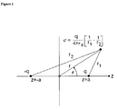
- the electric dipole has a positive charge q located on the z-axis at a distance a from the origin of the graph.
- a second negative charge ⁇ q is located at a distance ⁇ a from the origin.
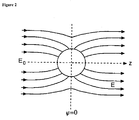
- the previously uniform electric field is shown perturbed by the neutral conducting sphere.
- the center of the sphere is taken as the origin and the z-axis is oriented parallel to the original uniform field.
- a neutral conducting sphere placed in a uniform electric field will generate a magnetic moment when rotated around a central axis.
- the electric field can be created by two points charges of opposite sign separated by a distance between them.
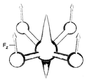
- the spacecraft has a spherical cabin (A) to which are attached cone-shaped electrostatic towers (B,C) above and below the cabin along the direction of travel in the z-direction. Because the electric field goes from the positive charge to the negative charge, the tip of the lower tower has a positively charged electrode, and the upper tower has a negatively charged electrode.
- Four equally-spaced neutral conducting spheres (D) are connected to the cabin by non-conducting tubes (E). The tubes make an angle with the cabin such that the distance (CD) is greater than distance (DB). The angle ⁇ of the tube with respect to the cabin can be seen in side view FIG. 4 .
- the charges create a uniform spherical field between the towers.
- the conducting spheres perturb this field such that the electric field (E) points toward the upper tower in a manner similar to that shown previously in FIG. 2 .
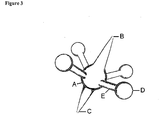
- the conducting sphere produces an electric dipole moment (A) pointing at an angle toward the upper tower.
- the electric dipole ⁇ overscore (p) ⁇ can be represented by two orthogonal vectors pointing in the vertical z-direction p z and in the inward radial direction p r .
- the hollow tube (A) connecting the cabin with the conducting sphere contains a spiral-wound electrical solenoid (B) which produces a magnetic field (C).
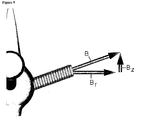
- This magnetic field ⁇ overscore (B) ⁇ can be decomposed into two orthogonal vectors pointing in the vertical z-direction B z and in the outward radial direction B r as shown in FIG. 9 .
- the spacecraft has a clockwise angular velocity ⁇ (A) which gives the conducting sphere a velocity v as shown by the vector (B).
- ⁇ (A) gives the conducting sphere a velocity v as shown by the vector (B).
- the angular velocity vector points in the negative z-direction.
- the angular velocity in the z-direction crossed with the radius r in the radial direction produces a velocity v in the clockwise ⁇ -direction using cylindrical coordinates ⁇ r, ⁇ ,z ⁇ .
- the magnetic field B z in the vertical z-direction is dotted with the magnetic moment ⁇ z in the z-direction to produce a force F z in the vertical z-direction on each conducting sphere ( FIG. 13 ).
- the magnetic field that is produced by the solenoid actually curves away and around. Thus there is a gradient of the field in the z-direction.
- the force can also be expressed in tensor notation.
- the subscripts and superscripts have to match up on both sides of the equation.
- the electric dipole moment is in the radial direction p r .
- the spacecraft design also has an inherent motion control system for moving in various directions. If the magnetic field of one solenoid arm is increased or decreased, the force on that sphere will be increased or decreased. Thus the spacecraft can turn in a particular direction.
- FIG. 1 Electric dipole.
- FIG. 2 Uniform electric field perturbed by electric dipole.
- FIG. 3 Perspective view of spacecraft.
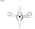
- FIG. 4 Angle of solenoid tube.
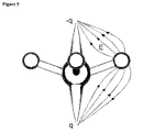
- FIG. 5 Electric field perturbed by conducting sphere.
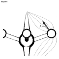
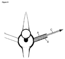
- FIG. 6 Electric dipole generated by conducting sphere.
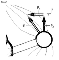
- FIG. 7 Orthogonal vector components of electric dipole.
- FIG. 8 Magnetic field produced by tube arm solenoid.
- FIG. 9 Orthogonal vector components of magnetic field.
- FIG. 10 Angular velocity of hull.
- FIG. 11 Magnetic moment produced by radial electric dipole and sphere velocity.
- FIG. 12 Dot product of the magnetic moment with the magnetic field.
- FIG. 13 Vertical lift force on all four conducting spheres.
- FIG. 14 Perpective view of spacecraft interior.
- the construction of the spacecraft is a thin-wall insulating thermoplastic having a dielectric constant in the range of 20 kilovolts per millimeter (A).
- An insulated electrode (B) runs from the cabin power supply and high-voltage transformer (C) to the tip of each tower (D).
- the four spheres (E) are silver plated to make them conducting.
- the tube solenoids (F) are driven by a direct current power supply (G).
- the present model uses 3D computer design software and stereolithography fabrication techniques to create the thin-wall, low-weight, hollow structure of the hull.
- the computer model is sliced into many thin horizontal slices.
- a laser mounted on an x-y table, draws out the slice on a table immersed in a bath of liquid polymer. Due to its sensitivity to the light, the liquid polymerizes. The table is then lowered a few thousandths of an inch more and the process is repeated.
- Parts can be designed and stored in *.STL stereolithography files for transmission by Internet e-mail to the service bureau machine shop which sends the finished parts back the next day by express mail.
Abstract
This invention is a rotating spacecraft that produces an electric dipole on four rotating spherical conducting domes perturbing a uniform spherical electric field to create a magnetic moment interacting with the gradient of a magnetic field that generates a lift force on the hull.
Description
- This invention is a rotating spacecraft that utilizes four spherical conducting domes perturbing a uniform electric field in order to create a lift force by means of a magnetic moment times the gradient of a magnetic field.
- An electric dipole p is two electrical charges of opposite sign {q, −q} separated by a distance a.
p=qa=coulomb·meter - If this dipole is moving with a velocity v, it produces a magnetic moment μ.
- The magnetic moment is equal to a current I circulating around an area. The magnetic field B has units of kilogram per second per charge coulomb.
- The gradient of the magnetic field in the vertical direction z has units of
- This gradient interacting with a magnetic moment creates a force F measured in newtons.
- In terms of vectors, the force is equal to
F=∇(μ·B)
which is the gradient ∇ of the dot product (·) of the magnetic moment with the magnetic field. This means that the magnetic moment has to be aligned with the field. The lift force on the spacecraft would then be the magnetic moment in the vertical z-direction μz times the magnetic field in the z-direction Bz. For constant magnetic moment, the gradient affects the magnetic field only, resulting in the same force equation
F z=∇(μz ·B z)=μz ∇B z - Referring to
FIG. 1 , the electric dipole has a positive charge q located on the z-axis at a distance a from the origin of the graph. A second negative charge −q is located at a distance −a from the origin. The positive charge produces an electrostatic potential φ1 at a radius r1 equal to the charge q divided by 4π times the permittivity of space ε0
where the permittivity is linear capacitance, measured in farads per meter. The electrostatic potential has units of volts
because the charge in coulombs held by a capacitor is equal to the capacitance, measured in farads, times the capacitor voltage. Because the second charge has the opposite sign, the potential φ2 at a radius r2 to the same point in space is - The total potential φ at some point in space is equal to the sum of the two potentials, or
- As seen in the diagram, the point of space is a distance r from the origin. Using the law of cosines, radius r1 can be written as
where t is the ratio of the charge location over the radius, and x is cos(θ). The potential for positive charge q1 can be written - Dropping the factor q/4πε0r, the square root can be expressed in terms of the Legendre polynomial Pn cos(θ) of the nth power
where the absolute value of t is less than one. The polynomial coefficients of tn can be obtained by using the binomial theorem to expand the generating function g(t,x) as
which evaluates to - The first three Legendre polynomials are therefore
- The electrostatic potential for both charges of the electric dipole is
- The potential can be evaluated in terms of the Legendre polynomials as
- The first and most dominant term when the radius is much greater than location a is equal to
which is the electric dipole potential and 2aq is the dipole moment
p=2aq - Now imagine a constant electric field E0 which is perturbed by a conducting sphere of radius a. The unperturbed electrostatic potential outside the sphere would the negative of the electric field times the radius times the Legendre polynomial, or
φ1 =−E 0 rP 1 - The electrostatic potential perturbed by the charges is the voltage E0a times the radius a times the a of the dipole moment times the Legendre polynomial divided by the radius squared
- The total potential outside the sphere is the sum of the two potentials equal to
- Referring to
FIG. 2 , the previously uniform electric field is shown perturbed by the neutral conducting sphere. The center of the sphere is taken as the origin and the z-axis is oriented parallel to the original uniform field. - The electric field induces a surface charge density σ on the sphere equal to the negative of the permittivity of space times the gradient of the electrostatic potential
- The electric field also induces an electric dipole moment on the sphere equal to the
with units of coulomb-meter. If this sphere is rotating around a central axis at a velocity v, it will create a magnetic moment μ equal to the dipole moment times the velocity.
μ=pv
with units of ampere-meter2. - As shown in the preceding background section, a neutral conducting sphere placed in a uniform electric field will generate a magnetic moment when rotated around a central axis. The electric field can be created by two points charges of opposite sign separated by a distance between them.
- Referring to
FIG. 3 , the spacecraft has a spherical cabin (A) to which are attached cone-shaped electrostatic towers (B,C) above and below the cabin along the direction of travel in the z-direction. Because the electric field goes from the positive charge to the negative charge, the tip of the lower tower has a positively charged electrode, and the upper tower has a negatively charged electrode. Four equally-spaced neutral conducting spheres (D) are connected to the cabin by non-conducting tubes (E). The tubes make an angle with the cabin such that the distance (CD) is greater than distance (DB). The angle θ of the tube with respect to the cabin can be seen in side viewFIG. 4 . - Referring to
FIG. 5 , the charges create a uniform spherical field between the towers. The conducting spheres perturb this field such that the electric field (E) points toward the upper tower in a manner similar to that shown previously inFIG. 2 . - Referring to
FIG. 6 , the conducting sphere produces an electric dipole moment (A) pointing at an angle toward the upper tower. - Referring to
FIG. 7 , by the law of addition of vectors, the electric dipole {overscore (p)} can be represented by two orthogonal vectors pointing in the vertical z-direction pz and in the inward radial direction pr. - Referring to
FIG. 8 , the hollow tube (A) connecting the cabin with the conducting sphere contains a spiral-wound electrical solenoid (B) which produces a magnetic field (C). This magnetic field {overscore (B)} can be decomposed into two orthogonal vectors pointing in the vertical z-direction Bz and in the outward radial direction Br as shown inFIG. 9 . - Referring to top-view
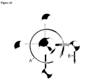
FIG. 10 , the spacecraft has a clockwise angular velocity ω (A) which gives the conducting sphere a velocity v as shown by the vector (B). By the right-hand rule of physics, the angular velocity vector points in the negative z-direction. The angular velocity in the z-direction crossed with the radius r in the radial direction produces a velocity v in the clockwise θ-direction using cylindrical coordinates {r,θ,z}.
v θ =w z ×r r =−ωr - Referring to
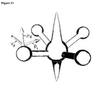
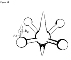
FIG. 11 , the negative radial dipole moment pr crossed with the negative velocity vθ of the sphere produces a positive magnetic moment μz in the z-direction.
μz =p r ×v θ=(−p r)(−v θ)=pv - Referring to
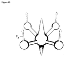
FIG. 12 , the magnetic field Bz in the vertical z-direction is dotted with the magnetic moment μz in the z-direction to produce a force Fz in the vertical z-direction on each conducting sphere (FIG. 13 ).
F z=∇(μz ·B z)=μz ∇B z - The magnetic field that is produced by the solenoid actually curves away and around. Thus there is a gradient of the field in the z-direction.
- The force can also be expressed in tensor notation. The magnetic B field in the vertical direction is part of an electromagnetic 4×4 matrix Faraday tensor F
which shows that the magnetic field is located in slot Fr θ of the Faraday tensor. In tensor notation the subscripts and superscripts have to match up on both sides of the equation. Matching subscripts and superscripts on the same side of the equation cancel. In this case, the electric dipole moment is in the radial direction pr. The velocity can be represented as a time derivative of the θ-coordinate xθ or - Thus the force component in the z-direction becomes
where the angular and radial tensor components cancel and comma-z (, z) represents differentiation of the magnetic field in the z-direction. - The spacecraft design also has an inherent motion control system for moving in various directions. If the magnetic field of one solenoid arm is increased or decreased, the force on that sphere will be increased or decreased. Thus the spacecraft can turn in a particular direction.
-
FIG. 1 . Electric dipole. -
FIG. 2 . Uniform electric field perturbed by electric dipole. -
FIG. 3 . Perspective view of spacecraft. -
FIG. 4 . Angle of solenoid tube. -
FIG. 5 . Electric field perturbed by conducting sphere. -
FIG. 6 . Electric dipole generated by conducting sphere. -
FIG. 7 . Orthogonal vector components of electric dipole. -
FIG. 8 . Magnetic field produced by tube arm solenoid. -
FIG. 9 . Orthogonal vector components of magnetic field. -
FIG. 10 . Angular velocity of hull. -
FIG. 11 . Magnetic moment produced by radial electric dipole and sphere velocity. -
FIG. 12 . Dot product of the magnetic moment with the magnetic field. -
FIG. 13 . Vertical lift force on all four conducting spheres. -
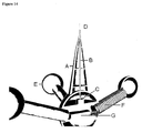
FIG. 14 . Perpective view of spacecraft interior. - 1. Referring to the cut-away view
FIG. 14 , the construction of the spacecraft is a thin-wall insulating thermoplastic having a dielectric constant in the range of 20 kilovolts per millimeter (A). An insulated electrode (B) runs from the cabin power supply and high-voltage transformer (C) to the tip of each tower (D). The four spheres (E) are silver plated to make them conducting. The tube solenoids (F) are driven by a direct current power supply (G). - 2. The present model uses 3D computer design software and stereolithography fabrication techniques to create the thin-wall, low-weight, hollow structure of the hull. The computer model is sliced into many thin horizontal slices. A laser, mounted on an x-y table, draws out the slice on a table immersed in a bath of liquid polymer. Due to its sensitivity to the light, the liquid polymerizes. The table is then lowered a few thousandths of an inch more and the process is repeated. Thus making hollow spherical and conical shapes is extremely easy to do. Parts can be designed and stored in *.STL stereolithography files for transmission by Internet e-mail to the service bureau machine shop which sends the finished parts back the next day by express mail.
Claims (2)
1. A spacecraft comprising:
a. a spherical cabin;
b. an electrostatic conical tower mounted on top of item (1 a), supporting a vertically-mounted negatively-charged insulated electrode at the tip of the tower;
c. an electrostatic conical tower mounted on the bottom of item (1 a), supporting a vertically-mounted positively-charged insulated electrode at the tip of the tower;
d. a vertical electric dipole created by items (1 b) and (1 c);
e. a high-voltage transformer to drive item (1 d), mounted in item (1 a);
f. four tubular arms, mounted at 90° around and extending at an angle from item (1 a);
g. four solenoids, each of which is mounted axially inside item (1 f);
h. a direct current power supply to drive item (1 g);
i. four silver-plated conducting spheres, each of which is mounted on the end of item (1 f);
2. an electrostatic lift system that:
a. produces a uniform spherical electric field by means of item (1 d) which envelopes item (1 i);
b. produces a perturbed electric field due to the presence of item (1 i);
c. produces an electric dipole moment in the direction of item (1 b) due to items (2 a) and (2 b);
d. produces a vertical magnetic moment due to the clockwise angular velocity of item (1 a) combined with item (2 c);
e. produces a vertical lift force on item (1 i) due to item (2 d) combined with the magnetic field gradient in the vertical direction produced by item (1 g); and
f. creates a motion control system by varying the current to item (1 g) in order to increase or decrease the effect of item (2 e) on a particular item (1 i).
Priority Applications (1)
| Application Number | Priority Date | Filing Date | Title |
|---|---|---|---|
| US10/912,621 US20060038081A1 (en) | 2004-08-04 | 2004-08-04 | Electric dipole spacecraft |
Applications Claiming Priority (1)
| Application Number | Priority Date | Filing Date | Title |
|---|---|---|---|
| US10/912,621 US20060038081A1 (en) | 2004-08-04 | 2004-08-04 | Electric dipole spacecraft |
Publications (1)
| Publication Number | Publication Date |
|---|---|
| US20060038081A1 true US20060038081A1 (en) | 2006-02-23 |
Family
ID=35908755
Family Applications (1)
| Application Number | Title | Priority Date | Filing Date |
|---|---|---|---|
| US10/912,621 Abandoned US20060038081A1 (en) | 2004-08-04 | 2004-08-04 | Electric dipole spacecraft |
Country Status (1)
| Country | Link |
|---|---|
| US (1) | US20060038081A1 (en) |
Cited By (2)
| Publication number | Priority date | Publication date | Assignee | Title |
|---|---|---|---|---|
| US20060145019A1 (en) * | 2004-12-20 | 2006-07-06 | St Clair John Q | Triangular spacecraft |
| IT202100015986A1 (en) * | 2021-06-18 | 2022-12-18 | Emidio Laureti | Electromagnetic propulsion system for the movement of space vehicles without the emission of reaction mass. |
Citations (6)
| Publication number | Priority date | Publication date | Assignee | Title |
|---|---|---|---|---|
| US2835548A (en) * | 1957-08-01 | 1958-05-20 | Robert C Baumann | Satellite structure |
| US3095167A (en) * | 1960-01-05 | 1963-06-25 | Horace C Dudley | Apparatus for the promotion and control of vehicular flight |
| US3114517A (en) * | 1959-05-12 | 1963-12-17 | Raytheon Co | Microwave operated space vehicles |
| US3348352A (en) * | 1964-04-16 | 1967-10-24 | North American Aviation Inc | Foldable structure |
| US3420469A (en) * | 1966-07-22 | 1969-01-07 | Thiokol Chemical Corp | Passive communications satellite or similar article |
| US6193194B1 (en) * | 1998-09-01 | 2001-02-27 | Michael A. Minovitch | Magnetic propulsion system and operating method |
-
2004
- 2004-08-04 US US10/912,621 patent/US20060038081A1/en not_active Abandoned
Patent Citations (6)
| Publication number | Priority date | Publication date | Assignee | Title |
|---|---|---|---|---|
| US2835548A (en) * | 1957-08-01 | 1958-05-20 | Robert C Baumann | Satellite structure |
| US3114517A (en) * | 1959-05-12 | 1963-12-17 | Raytheon Co | Microwave operated space vehicles |
| US3095167A (en) * | 1960-01-05 | 1963-06-25 | Horace C Dudley | Apparatus for the promotion and control of vehicular flight |
| US3348352A (en) * | 1964-04-16 | 1967-10-24 | North American Aviation Inc | Foldable structure |
| US3420469A (en) * | 1966-07-22 | 1969-01-07 | Thiokol Chemical Corp | Passive communications satellite or similar article |
| US6193194B1 (en) * | 1998-09-01 | 2001-02-27 | Michael A. Minovitch | Magnetic propulsion system and operating method |
Cited By (3)
| Publication number | Priority date | Publication date | Assignee | Title |
|---|---|---|---|---|
| US20060145019A1 (en) * | 2004-12-20 | 2006-07-06 | St Clair John Q | Triangular spacecraft |
| IT202100015986A1 (en) * | 2021-06-18 | 2022-12-18 | Emidio Laureti | Electromagnetic propulsion system for the movement of space vehicles without the emission of reaction mass. |
| WO2022264177A1 (en) | 2021-06-18 | 2022-12-22 | Laureti Emidio | Electromagnetic propulsion system for spacecraft movement without the emission of reaction mass |
Similar Documents
| Publication | Publication Date | Title |
|---|---|---|
| Priest et al. | A converging flux model of an X-ray bright point and an associated canceling magnetic feature | |
| Virbhadra | Angular momentum distribution in Kerr-Newman spacetime | |
| US20190168897A1 (en) | Segmented Current Magnetic Field Propulsion System | |
| WO1992007657A1 (en) | Process for manipulating microscopically small dielectric particles and device for implementing the process | |
| Moesner et al. | Electrostatic devices for particle microhandling | |
| JP2009207176A (en) | Field converter | |
| Yudistira et al. | Retreat behavior of a charged droplet for electrohydrodynamic inkjet printing | |
| US20060038081A1 (en) | Electric dipole spacecraft | |
| US11511891B2 (en) | System and method for generating forces using asymmetrical electrostatic pressure | |
| AU2002356822A1 (en) | Field converter | |
| US10084395B2 (en) | Complex electric fields and static electric fields to effect motion with conduction currents | |
| Bisnovatyi-Kogan et al. | Particle acceleration in extragalactic jets by intense long-wavelength electromagnetic fields | |
| Blümel et al. | Bound states of neutrons in the cylindrically symmetric magnetic field of a thin current carrying wire | |
| Chen et al. | The morphology of a multi‐bubble system in the ionosphere | |
| Wilson et al. | Electromagnetic, Free-Flying Mobility Relative to a Conductive Body | |
| Abdikian et al. | Lattice modes in a zigzag crystal of dust particles | |
| US20060145019A1 (en) | Triangular spacecraft | |
| CLAIR | Correspondence Address | |
| TWI280408B (en) | Field converter | |
| Hose et al. | Observations on the regular and irregular motion as exemplified by the quadratic Zeeman effect and other systems | |
| Mele et al. | Chiral liquid states in a spin-free representation for the diluted Mott insulator | |
| US20060168937A1 (en) | Magnetic monopole spacecraft | |
| Saisutjarit et al. | Trajectory optimization of a multi-tethered space robot on large spinning net structures | |
| García et al. | Energy spectrum of shallow donor in elongated InAs/GaAs volcano-shaped quantum dot | |
| Noonan | On test particles in general relativity |
Legal Events
| Date | Code | Title | Description |
|---|---|---|---|
| STCB | Information on status: application discontinuation |
Free format text: ABANDONED -- FAILURE TO RESPOND TO AN OFFICE ACTION |