US10079765B2 - System and methods for assigning slots and resolving slot conflicts in an electrical distribution grid - Google Patents
System and methods for assigning slots and resolving slot conflicts in an electrical distribution grid Download PDFInfo
- Publication number
- US10079765B2 US10079765B2 US14/928,783 US201514928783A US10079765B2 US 10079765 B2 US10079765 B2 US 10079765B2 US 201514928783 A US201514928783 A US 201514928783A US 10079765 B2 US10079765 B2 US 10079765B2
- Authority
- US
- United States
- Prior art keywords
- slot
- time slot
- downstream
- message time
- segment
- Prior art date
- Legal status (The legal status is an assumption and is not a legal conclusion. Google has not performed a legal analysis and makes no representation as to the accuracy of the status listed.)
- Expired - Fee Related
Links
Images


Classifications
-
- H—ELECTRICITY
- H04—ELECTRIC COMMUNICATION TECHNIQUE
- H04L—TRANSMISSION OF DIGITAL INFORMATION, e.g. TELEGRAPHIC COMMUNICATION
- H04L47/00—Traffic control in data switching networks
- H04L47/10—Flow control; Congestion control
- H04L47/12—Avoiding congestion; Recovering from congestion
- H04L47/122—Avoiding congestion; Recovering from congestion by diverting traffic away from congested entities
-
- H—ELECTRICITY
- H02—GENERATION; CONVERSION OR DISTRIBUTION OF ELECTRIC POWER
- H02J—CIRCUIT ARRANGEMENTS OR SYSTEMS FOR SUPPLYING OR DISTRIBUTING ELECTRIC POWER; SYSTEMS FOR STORING ELECTRIC ENERGY
- H02J13/00—Circuit arrangements for providing remote indication of network conditions, e.g. an instantaneous record of the open or closed condition of each circuitbreaker in the network; Circuit arrangements for providing remote control of switching means in a power distribution network, e.g. switching in and out of current consumers by using a pulse code signal carried by the network
- H02J13/00006—Circuit arrangements for providing remote indication of network conditions, e.g. an instantaneous record of the open or closed condition of each circuitbreaker in the network; Circuit arrangements for providing remote control of switching means in a power distribution network, e.g. switching in and out of current consumers by using a pulse code signal carried by the network characterised by information or instructions transport means between the monitoring, controlling or managing units and monitored, controlled or operated power network element or electrical equipment
- H02J13/00016—Circuit arrangements for providing remote indication of network conditions, e.g. an instantaneous record of the open or closed condition of each circuitbreaker in the network; Circuit arrangements for providing remote control of switching means in a power distribution network, e.g. switching in and out of current consumers by using a pulse code signal carried by the network characterised by information or instructions transport means between the monitoring, controlling or managing units and monitored, controlled or operated power network element or electrical equipment using a wired telecommunication network or a data transmission bus
- H02J13/00017—Circuit arrangements for providing remote indication of network conditions, e.g. an instantaneous record of the open or closed condition of each circuitbreaker in the network; Circuit arrangements for providing remote control of switching means in a power distribution network, e.g. switching in and out of current consumers by using a pulse code signal carried by the network characterised by information or instructions transport means between the monitoring, controlling or managing units and monitored, controlled or operated power network element or electrical equipment using a wired telecommunication network or a data transmission bus using optical fiber
-
- H—ELECTRICITY
- H02—GENERATION; CONVERSION OR DISTRIBUTION OF ELECTRIC POWER
- H02J—CIRCUIT ARRANGEMENTS OR SYSTEMS FOR SUPPLYING OR DISTRIBUTING ELECTRIC POWER; SYSTEMS FOR STORING ELECTRIC ENERGY
- H02J13/00—Circuit arrangements for providing remote indication of network conditions, e.g. an instantaneous record of the open or closed condition of each circuitbreaker in the network; Circuit arrangements for providing remote control of switching means in a power distribution network, e.g. switching in and out of current consumers by using a pulse code signal carried by the network
- H02J13/00032—Systems characterised by the controlled or operated power network elements or equipment, the power network elements or equipment not otherwise provided for
- H02J13/00034—Systems characterised by the controlled or operated power network elements or equipment, the power network elements or equipment not otherwise provided for the elements or equipment being or involving an electric power substation
-
- H—ELECTRICITY
- H04—ELECTRIC COMMUNICATION TECHNIQUE
- H04B—TRANSMISSION
- H04B3/00—Line transmission systems
- H04B3/54—Systems for transmission via power distribution lines
-
- H—ELECTRICITY
- H04—ELECTRIC COMMUNICATION TECHNIQUE
- H04L—TRANSMISSION OF DIGITAL INFORMATION, e.g. TELEGRAPHIC COMMUNICATION
- H04L47/00—Traffic control in data switching networks
- H04L47/10—Flow control; Congestion control
- H04L47/11—Identifying congestion
-
- H—ELECTRICITY
- H04—ELECTRIC COMMUNICATION TECHNIQUE
- H04L—TRANSMISSION OF DIGITAL INFORMATION, e.g. TELEGRAPHIC COMMUNICATION
- H04L5/00—Arrangements affording multiple use of the transmission path
- H04L5/003—Arrangements for allocating sub-channels of the transmission path
- H04L5/0053—Allocation of signaling, i.e. of overhead other than pilot signals
-
- H—ELECTRICITY
- H02—GENERATION; CONVERSION OR DISTRIBUTION OF ELECTRIC POWER
- H02J—CIRCUIT ARRANGEMENTS OR SYSTEMS FOR SUPPLYING OR DISTRIBUTING ELECTRIC POWER; SYSTEMS FOR STORING ELECTRIC ENERGY
- H02J13/00—Circuit arrangements for providing remote indication of network conditions, e.g. an instantaneous record of the open or closed condition of each circuitbreaker in the network; Circuit arrangements for providing remote control of switching means in a power distribution network, e.g. switching in and out of current consumers by using a pulse code signal carried by the network
- H02J13/00006—Circuit arrangements for providing remote indication of network conditions, e.g. an instantaneous record of the open or closed condition of each circuitbreaker in the network; Circuit arrangements for providing remote control of switching means in a power distribution network, e.g. switching in and out of current consumers by using a pulse code signal carried by the network characterised by information or instructions transport means between the monitoring, controlling or managing units and monitored, controlled or operated power network element or electrical equipment
- H02J13/00007—Circuit arrangements for providing remote indication of network conditions, e.g. an instantaneous record of the open or closed condition of each circuitbreaker in the network; Circuit arrangements for providing remote control of switching means in a power distribution network, e.g. switching in and out of current consumers by using a pulse code signal carried by the network characterised by information or instructions transport means between the monitoring, controlling or managing units and monitored, controlled or operated power network element or electrical equipment using the power network as support for the transmission
-
- Y—GENERAL TAGGING OF NEW TECHNOLOGICAL DEVELOPMENTS; GENERAL TAGGING OF CROSS-SECTIONAL TECHNOLOGIES SPANNING OVER SEVERAL SECTIONS OF THE IPC; TECHNICAL SUBJECTS COVERED BY FORMER USPC CROSS-REFERENCE ART COLLECTIONS [XRACs] AND DIGESTS
- Y02—TECHNOLOGIES OR APPLICATIONS FOR MITIGATION OR ADAPTATION AGAINST CLIMATE CHANGE
- Y02E—REDUCTION OF GREENHOUSE GAS [GHG] EMISSIONS, RELATED TO ENERGY GENERATION, TRANSMISSION OR DISTRIBUTION
- Y02E60/00—Enabling technologies; Technologies with a potential or indirect contribution to GHG emissions mitigation
-
- Y—GENERAL TAGGING OF NEW TECHNOLOGICAL DEVELOPMENTS; GENERAL TAGGING OF CROSS-SECTIONAL TECHNOLOGIES SPANNING OVER SEVERAL SECTIONS OF THE IPC; TECHNICAL SUBJECTS COVERED BY FORMER USPC CROSS-REFERENCE ART COLLECTIONS [XRACs] AND DIGESTS
- Y04—INFORMATION OR COMMUNICATION TECHNOLOGIES HAVING AN IMPACT ON OTHER TECHNOLOGY AREAS
- Y04S—SYSTEMS INTEGRATING TECHNOLOGIES RELATED TO POWER NETWORK OPERATION, COMMUNICATION OR INFORMATION TECHNOLOGIES FOR IMPROVING THE ELECTRICAL POWER GENERATION, TRANSMISSION, DISTRIBUTION, MANAGEMENT OR USAGE, i.e. SMART GRIDS
- Y04S40/00—Systems for electrical power generation, transmission, distribution or end-user application management characterised by the use of communication or information technologies, or communication or information technology specific aspects supporting them
- Y04S40/12—Systems for electrical power generation, transmission, distribution or end-user application management characterised by the use of communication or information technologies, or communication or information technology specific aspects supporting them characterised by data transport means between the monitoring, controlling or managing units and monitored, controlled or operated electrical equipment
- Y04S40/121—Systems for electrical power generation, transmission, distribution or end-user application management characterised by the use of communication or information technologies, or communication or information technology specific aspects supporting them characterised by data transport means between the monitoring, controlling or managing units and monitored, controlled or operated electrical equipment using the power network as support for the transmission
-
- Y—GENERAL TAGGING OF NEW TECHNOLOGICAL DEVELOPMENTS; GENERAL TAGGING OF CROSS-SECTIONAL TECHNOLOGIES SPANNING OVER SEVERAL SECTIONS OF THE IPC; TECHNICAL SUBJECTS COVERED BY FORMER USPC CROSS-REFERENCE ART COLLECTIONS [XRACs] AND DIGESTS
- Y04—INFORMATION OR COMMUNICATION TECHNOLOGIES HAVING AN IMPACT ON OTHER TECHNOLOGY AREAS
- Y04S—SYSTEMS INTEGRATING TECHNOLOGIES RELATED TO POWER NETWORK OPERATION, COMMUNICATION OR INFORMATION TECHNOLOGIES FOR IMPROVING THE ELECTRICAL POWER GENERATION, TRANSMISSION, DISTRIBUTION, MANAGEMENT OR USAGE, i.e. SMART GRIDS
- Y04S40/00—Systems for electrical power generation, transmission, distribution or end-user application management characterised by the use of communication or information technologies, or communication or information technology specific aspects supporting them
- Y04S40/12—Systems for electrical power generation, transmission, distribution or end-user application management characterised by the use of communication or information technologies, or communication or information technology specific aspects supporting them characterised by data transport means between the monitoring, controlling or managing units and monitored, controlled or operated electrical equipment
- Y04S40/124—Systems for electrical power generation, transmission, distribution or end-user application management characterised by the use of communication or information technologies, or communication or information technology specific aspects supporting them characterised by data transport means between the monitoring, controlling or managing units and monitored, controlled or operated electrical equipment using wired telecommunication networks or data transmission busses
Definitions
- the present invention relates to data communication systems, methods and apparatus and more particularly to data communication systems methods and apparatus associated with electrical power distribution networks.
- the present invention provides a system and method for detecting and resolving conflicts in transmissions between, for example, downstream transmitters (hereinafter “DT” or “DTs”) located on the edge of an electrical power distribution grid and devices located at an associated substation.
- DT downstream transmitters
- reassigning the DT's transmission to another frame and time slot the conflict should be resolved and the data being provided by the DT is not necessarily lost nor is its receipt unreasonably delayed.
- the slot assignments for each of the transmissions is rescheduled.
- the identification of a possible conflicting DT may be an iterative process whereby if a conflict appears to exist after a DT has already been reassigned slot assignment(s), then another DT may need to have its slot assignment reassigned.
- the invention determines the conflict without regard to having a priori knowledge of the system topology and layout, or its electrical characteristics.
- the present invention provides a system and method for detecting and resolving transmissions by knowing to look for a signal to be received during a time slot. If, during that time slot, energy is detected within the communications passband and that is greater than noise on the system (i.e., candidate signal energy) and the length of the candidate signal energy is approximately the same length as a transmitted signal, then the system checks to see if a transmission header, e.g., a GLA signal, is present. If a GLA signal is present, then the signal is processed normally. If a GLA signal is not present, then the system checks which DT should be sending a transmission during that time slot, and reassigns that DT to another available time slot.
- a transmission header e.g., a GLA signal
- FIG. 1 is a simplified illustration of the power path from a generation point to a distribution substation to a consumer, showing the high voltage, medium voltage, and low voltage regions of the distribution grid and depicting some of the major features of an electrical distribution grid;
- FIG. 2 is a simplified illustration of a logical structure of domains of an exemplary electrical distribution grid, showing enterprise, region, substation, and transformer domains;
- FIG. 3 is a simplified block diagram of the substation apparatus in a Grid Location AwareTM network, illustrating how the Grid Location AwareTM network apparatus couples to the existing SCADA and/or protection relay lines in the substation and how the data from the Substation Receiver is backhauled to a data center;
- FIG. 4 is a simplified block diagram illustration of the invention showing major logical structures of the invention
- FIG. 5 is a simplified illustration of a portion of an exemplary slot structure showing six time slots in one frame from two channels;
- FIG. 6 is a simplified illustration of a data burst profile showing a first part with a GLA preamble data and a second part having Address, control, data, or CRC data;
- FIG. 7 is a simplified logical flow diagram of a methodology for an initial DT detection and assignment in accordance with an embodiment of the invention.
- FIG. 8 is a simplified logical flow diagram of a methodology for a slot assignment in accordance with an embodiment of the invention.
- FIG. 9 is a simplified logical flow diagram of another methodology for a slot assignment in accordance with an embodiment of the invention.
- FIG. 10 is a simplified logical flow diagram of a methodology for a decision process to assign a new slot in accordance with an embodiment of the invention
- FIG. 11 is a simplified illustration of a slot reassignment depicting a slot conflict occurring in Frame 1 , Slot 3 , a new slot assignment received in Frame 3 , and a DT of record being re-assigned to Frame 4 , Slot 5 ;
- FIG. 12 is a simplified logical flow diagram of a methodology for a single slot reassignment in accordance with an embodiment of the invention.
- FIG. 13 is a simplified logical flow diagram of a methodology for a multiple slot reassignment in accordance with an embodiment of the invention
- FIG. 14 is a simplified logical flow diagram of a methodology for resolving a conflicting DT in accordance with an embodiment of the invention.
- FIG. 15 is a simplified logical flow diagram of a methodology for an intentional reassignment of a DT in accordance with an embodiment of the invention.
- the present invention discloses a system and method of resolving slot conflicts between DTs which may require dynamically re-assigning at least one DT to a different time slot.
- the present invention comprises a system and methods for constructing and operating an on-grid data collection network in such a way as to resolve conflicts between transmissions from DTs that occur during at least partially at the same time and/or on substantially the same channel.
- the system integrates with other adjacent networks and devices present at the edge, substations, and features of an electrical distribution network, wherein the other networks and devices may include Smart Meters and the AMI and a conventional network such as the Internet.
- the system and methods may also employ the capabilities of the integrated networks to otherwise change DT transmission time with a reduced communication to the DT without significant delay in changing the transmission time and without losing the data to be transmitted by the DT. This leads to the ability of the system to increase timely data flow from the edge of a distribution grid, thereby supporting increased accuracy in the monitoring of demands and supplies on the system. models to support Smart Grid applications such as conservation voltage reduction, volt/Var optimization, load balancing, fault isolation, and recovery management.
- the present invention determines the existence of a slot assignment conflict and then the identification of the DT that is in conflict that should have its slot assignment(s) reassigned.
- the invention determines the identification of the DT in any of various ways including, but not limited to, looking up the identification of the DT that is assigned that slot assignment, determining the identification of the DT based on information from the payload data of the signal that was received, and determining the identification of the DT based on inferring the feeder and phase that the signal was received on and some information from the payload data of the signal that was received. Then the invention finds an available time slot, or if the DT requires multiple slots, then the invention finds time slots, to reassign the DT to.
- the DT is sent the new slot assignment(s) and stores that information within its system.
- the computer system also stores the slot assignment(s) for the DT in its system.
- the data associated with such communications can be transferred in a variety of ways. These include the application of dedicated and general-purpose electrical and optical transmission media, and various wireless schemes including existing cellular and satellite networks, among others.
- the present invention deals with the significant benefits available from employing direct data transmission through the power lines of the power transmission network itself.
- Communication across the power transmission media is desirable because of the intrinsic presence of such media between components of the system. While alternative transmission mechanisms are often available to devices on a smart grid and those alternatives may come at a lower cost than grid-based communications, they lack the ability to provide information about the grid. Thus, for example, a cellular or satellite communication system may be available between a substation and a DT, but communications over the corresponding data channel may incur variable per-communication costs which may be relatively low when compared to the fixed costs associated with the related communication hardware.
- the power transmission media of the network forms a noisy and dynamic channel that inhibits the reliable transport of communication signals.
- operation of the network includes the switching of various transmission links in and out of service, the addition and removal of passive and reactive loads and the connection and disconnection of various centralized and distributed generating nodes.
- inductive and capacitive crosstalk varying environmental factors and assorted failure modes of line-connected apparatus can result in the system as a whole having rapidly varying characteristics.
- the slot-assignment and conflict resolution features of the present invention will achieve, among other objectives:
- DTs include any of a variety of devices and systems, such as, e.g., general-purpose systems and systems with embedded computer technology, that are present in the vicinity of a consumer of electrical power, where that electrical power is received across a power transmission network.
- the grid location of such a consumer is generally referred to as the “edge of the network.”
- Central devices will be found in a variety of locations within the network that are distal with respect to the edge of the network and, most typically in the present context, at or in the vicinity of a power transmission substation.
- a “slot,” as in “slot assignments” and “time slot” will refer, for example, to the time intervals assigned by convention to various payload time intervals within a time-multiplexed data transmission. This will become clear to a reader of ordinary skill in the art in light of further description to follow below. Likewise, the meanings of the terms “foldover”, “asynchronous foldover”, “transmission conflict” and “conflict resolution” will become clear to the skilled reader in the course of the following disclosure. As these terms become understood, the nature and meaning of “slot reassignments” will naturally emerge to the reader.
- An electrical power grid is generally considered to be composed of two topological regions, the Transmission Grid(s) and the Distribution Grid(s).
- the Transmission Grid originates at large generation points such as hydroelectric dams, nuclear reactors, wind farms, and coal-fired or gas-fired power plants. Power from the generation point is transmitted as high-voltage alternating current (AC) over a loosely connected network of long, high-voltage lines to points where demand for power exists, such as factories, farms, and population centers.
- Distribution Substations are typically located at various points on the periphery or edge of a transmission grid.
- FIG. 1 illustrates a typical segment of an electrical power grid.
- An electrical power grid is generally considered to be composed of two logical regions, the Transmission Grid(s) and the Distribution Grid(s).
- the Transmission Grid originates at large generation points, e.g., power plant 120 , such as hydroelectric dams, nuclear reactors, wind farms, solar farms, and coal-fired or gas-fired power plants. Power from the generation point is transmitted as high-voltage alternating current (AC) over a connected network of long, high-voltage lines to points where demand for power exists, such as factories, farms, and population centers.
- AC high-voltage alternating current
- Distribution Substations e.g., distribution substation 124 .
- Distribution Substations contain one or more Substation Transformers which step down the voltage from high transmission line levels (typically 130 kV to 700 kV) to the medium voltage levels (currently typically from 4 kV to about 35 kV in the United States, higher voltages are currently used outside the United States, although the specific distribution voltage is not germane to the invention) at which power is distributed to consumers within a distribution service area.
- high transmission line levels typically 130 kV to 700 kV
- medium voltage levels currently typically from 4 kV to about 35 kV in the United States, higher voltages are currently used outside the United States, although the specific distribution voltage is not germane to the invention
- Service Transformers e.g., service transformer 136
- service transformer 136 which transform the medium voltage of the distribution grid to lower voltages (in the United States, typically 120V, 208V, 240V, 277V, or 480V).
- Other voltages in addition to some of these can be used elsewhere in the world.
- a tier of one or more transformers called step-down transformers, e.g., transformer 128 , lying schematically between the Substation Transformers and the Service Transformers, create intermediate voltage reductions between the Substation and the Service Transformers.
- Each Service Transformer powers one or more metered, e.g., using meter 142 , or unmetered loads.
- a load e.g., load 150
- a typical distribution grid includes other elements used to control, balance, and regulate the flow of power. Examples of such elements are capacitor banks, e.g., capacitor bank 132 , voltage regulators, switches, and reclosers.
- Distribution grids have been designed and deployed in a variety of topological configurations. In the United States, distribution grid types are typically characterized as radial, loop, or networked. Other emerging cases are the campus grids and microgrids. Additional topologies, not described, are used elsewhere in the world.
- a substation In a radial grid, a substation has one or more substation transformers. Each substation transformer has one or more substation busses. One or more three-phase feeders “radiate” outward from each substation bus, with single-phase, or three-phase lateral lines branching off from the feeders, and tap-off points (or simply “taps”) in turn branching from the laterals.
- Radial grids are inexpensive to design and build because they are simple, but they are most vulnerable to outages because they lack redundant power paths, so that any break causes at least one load to lose power.
- Network and loop grids are also well known to one of skill in the art and are equally amenable to supporting corresponding embodiments of the invention.
- a distribution substation receives high-voltage power from the transmission grid into one or more large power transformers.
- a distribution transformer may incorporate a type of regulator called a load-tap changer, which alters the voltage that the transformer delivers to a power distribution bus (a substation distribution bus) by including or excluding some turns of the secondary winding circuit of the transformer, thereby changing the ratio of input to output voltage. Certain embodiment of the invention will operate properly notwithstanding changes in these turns ratios.
- One or more feeders emanate from the substation bus. If too many feeders are required in order to service the loads or topology, additional transformers and busses are used.
- FIG. 2 is a simplified illustration of a logical structure of domains of an exemplary electrical distribution grid, showing enterprise, region, substation, and transformer domains.
- a power transmission grid can be viewed as consisting of a hierarchy of functional and logical domains “Domains.”
- a top level domain is referred to as an “Enterprise Domain.”
- An Enterprise Domain e.g., Enterprise Domain 210
- An Enterprise Domain 210 typically encompasses the entire distribution grid of a business stemming from an electrical generation system, e.g., a power plant to the edges of the grid.
- An Enterprise Domain 210 will generally encompass several “Regional Domains,” e.g., Regional Domain 214 .
- a Regional Domain (RD) can be further broken down into at least one Substation Domain, e.g., Substation Domain 220 .
- a Substation Domain includes the circuitry of a substation and circuits downstream.
- a Substation Domain (SD) 220 can be further broken down into at least one Transformer Domain, e.g., Transformer Domains 222 , 224 , 226 .
- a Transformer Domain includes a substation transformer converting voltage from transmission voltage to distribution voltage, and all circuits downstream of that transformer.
- a “domain” will refer to a Substation Domain.
- a physical substation will include one or more transformers, each defining a Transformer Domain.
- Each transformer domain can have various types of arrangements of circuits downstream.
- Each transformer provides one or more feeders and, conventionally, each feeder consists of three phases. It is conceivable to have a grid that includes several transformers, with each having one or more feeders, each feeder having three phases and supporting various subordinate circuitry. It will be appreciated by one of skill in the art, however, that other phase arrangements are possible and are considered to be within the scope of the invention.
- feeder/phase current transformers In order to monitor and control the components of the grid, feeder/phase current transformers (FPCTs) are attached to power-bearing conductors within the substation.
- the FPCTs output a relatively low alternating current (typically up to 5 amps) on a looped conductor which is accurately proportional to the current flowing through the high voltage conductor being monitored.
- SCADA Supervisory Control and Data Acquisition
- FPCTs are designed and built into the substation, because changing or adding FPCTs to the high-voltage components is impossible or dangerous while current is flowing.
- additional monitoring CTs MCTs
- MCTs may be safely added around the low-current loops as needed without impacting power delivery, the protection circuits, or the accuracy of the SCADA system.
- the distribution grid contains numerous other devices intended to regulate, isolate, stabilize, and divert the flow of power. These devices include switches, reclosers, capacitor banks (usually for power factor or voltage correction), and secondary voltage regulators. All these devices affect the behavior of the distribution grid when considered as a data-bearing network, as do the various loads and secondary power sources on the grid. Devices that have abrupt state changes will introduce impulse noise on the grid, as can loads turning on and off. Some devices, such as transformers and capacitor banks, filter and attenuate signals at certain frequencies and can cause cross-talk of signals above the fundamental frequency of the power delivery system.
- the service transformer is typically the outermost element of the distribution grid before the power is actually delivered to a consumer.
- the meter is attached at the point where the power from the service transformer is delivered to the consumer.
- Service transformers can be three-phase or single phase, as can meters.
- reading meters was one of the largest operational costs incurred by electrical utilities.
- Original electric meters were analog devices with an optical read-out that had to be manually examined monthly to drive the utility billing process.
- mechanisms for digitizing meter data and automating its collection began to be deployed. These mechanisms evolved from walk-by or drive-by systems where the meter would broadcast its current reading using a short-range radio signal, which was received by a device carried by the meter reader. These early systems were known as Automated Meter Reading systems or AMRs.
- AMRs Automated Meter Reading systems
- AMRs Automated Meter Reading systems
- AMRs Automated Meter Reading systems
- AMRs Automated Meter Reading systems
- a variety of purpose-built data collection networks employing a combination of short-range RF repeaters in a mesh configuration with collection points equipped with broadband backhaul means for transporting aggregated readings began to be deployed.
- two-way purpose-build collection networks utilizing two-way paging technology and cellular communications were also deployed, either as independent systems, or as
- AMIs can collect and store readings frequently, typically as often as every 15 minutes, and can report them nearly that often across an entire deployment. They can read any meter on demand provided that this feature is used sparingly, and can connect or disconnect any meter on demand as well.
- AMI meters can pass signals to consumer devices for the purpose of energy conservation, demand management, and variable-rate billing. Because the AMI network is separate from the power distribution grid, AMI meters are neither aware of nor sensitive to changes in the grid topology or certain conditions on the grid. Nonetheless, the introduction of AMI is generally considered to be the beginning of the Smart Grid.
- the grid is a noisy environment. State changes in loads on the grid, as well as control and regulation artifacts on the grid itself, cause impulse noise on the power line. Normal operation of loads like electrical motors, simple variations in the overall load, and ambient RF noise (chiefly from lightening and other weather-related causes) add up to significant Gaussian noise.
- the measured noise floor at a typical substation in the United States sits at about 80-90 dB below the maximum amplitude of the line fundamental frequency.
- the complex impedance of the grid varies across both the frequency and time domains. This may lead to loss of signal at an on-grid receiver sited at a higher voltage point on the grid when impedance increases, or alternately force the on-grid transmitter to use more energy than would be necessary on the average.
- Capacitor banks sited at points along the grid for the purpose of optimizing power factor can cause signal attenuation. These capacitor banks can be static values or dynamic values, which are changed manually or automatically. Most significantly, transformers act as low-pass filters, dramatically attenuating signals above a certain frequency. The effective passband is not the same on every distribution grid, because different arrangements and types of transformers are employed and because the transformers themselves are not deliberately tuned to filter at a specified frequency above the fundamental. All these variables impact the frequency response of the grid as a transmission medium.
- crosstalk where a signal injected on one power line is detectable on another line.
- Crosstalk When crosstalk occurs on two or more phases of the same feeder, it can be caused by inductive and/or capacitive coupling as the phase lines run alongside one another for most of the length of the feeder.
- Crosstalk may also be due to multiple phase windings on the same transformer core, and may be caused by reflection of the injected signal off the power bus at the substation.
- Feeder-to-feeder crosstalk has also been measured, and may be caused by reflection of the injected signal off the power bus at the substation.
- the amplitude of a signal received at a substation may be higher (at some frequencies) on a crosstalk channel (feeder/phase), than on the originating feeder/phase. Given the complexity, diversity, and age of the distribution grids in the United States and the world, less is known about these phenomena at frequencies above the fundamental than might be expected.
- FIG. 3 is a logical block diagram of the intelligent platforms of one embodiment of the invention, showing where the processing elements reside with respect to a network.
- the exemplary network illustrated includes a wide area network such as the Internet, an AMI, and a medium voltage electrical distribution grid, or other such medium. Connected at the edge, or an internal junction point, of the medium voltage electrical distribution grid is at least one DT.
- FIG. 3 shows that the system may be divided into three regions or tiers.
- the edge tier 301 includes at least one DT.
- the DT e.g., DT 305
- the DT can be located at a service transformer 303 or the DT, e.g., DT 304 , can be located at a power consumption site underneath the service transformer.
- the invention does not require the installation of communication devices or other modifications between the edge tier and the substation tier.
- a variation of the DT may be installed there.
- Such a DT is technically still at the Edge Tier, since it is powered by a low-voltage outlet located at the feature, and not directly from the medium-voltage line(s) upon which the grid feature is installed.
- the substation tier 306 comprises at least one Substation Receiver 307 operable to receive transmissions from the DT in the edge tier, or intermediate junction point, without recourse to any signal amplifiers, bypass mechanisms, or bridges installed on the medium voltage infrastructure of the electrical distribution grid.
- the Substation Receiver(s) connect via a local area network to a Computing Platform 308 containing non-volatile computer-readable memory and a CPU for storing and executing the software 309 which maintains the Inventory and Grid Map databases and carries out the tasks of provisioning and managing the data network.
- the Computing Platform stores and executes software 310 which processes the Inventory and Grid Map data in combination with messages received from the Substation Receiver 307 to infer information about the state of the Grid over and above what the Substation Receiver alone can detect based only on incoming transmissions.
- the combination of the substation receiver 307 and its associated computing platform 308 is also referred to as a Feeder Intelligence Module (FIM).
- FIM Feeder Intelligence Module
- a substation receiver 307 includes a number of analog-to-digital (A/D) converters, although typically depicted as the A/D converter being located outside of a substation receiver 307 .
- A/D converter is coupled to a prospective sensor on each feeder phase looped conductor, i.e., each phase of each feeder supports an A/D converter.
- the signals received from the phases of the feeders are current wave forms.
- the A/D converter is located near each MCT on each respective feeder phase input line. ( FIG. 4 )
- the FIM includes MCTs coupled to the outputs of the FPCTs.
- the outputs of the MCTs are, in turn, connected to the inputs of the A/D converters respectively.
- the A/Ds are located near the respective MCT on each feeder phase current loop. ( FIG. 3 )
- the substation receiver 307 ignores signals at the grid's fundamental line frequency and its integer harmonics.
- each distribution substation has at least one substation transformer.
- the substation transformer and its topology-the circuits and features between the substation transformer and its loads, inclusive- is generally referred to as a Substation Domain.
- the system includes a substation receiver 307 uniquely associated with each substation transformer.
- the substation tier 306 has two substation domains corresponding to the two substation receivers 307 .
- a substation receiver 307 is shared by more than one substation domain, or a substation domain has more than one substation receiver.
- the computer-based components of the Substation Receiver and the Computing Platform components are hosted on the same processing subsystem.
- the communications protocol such as HTTP
- the communications protocol used to transfer data between the Substation Receiver and the Computing Platform software components need not change, even though there is no physical local area network required.
- Computing Platform 308 connects to a conventional wide area network 311 , such as the Internet, for the purpose of communicating with a Concentrator 312 in a data center tier 313 .
- a conventional wide area network 311 such as the Internet
- the processing subsystems may be configured in a redundant cluster to ensure continuous operation of the system.
- the Concentrator 312 hosts software with an analogous architecture to the software in the substation(s).
- Such an architecture may include a network and data management component 314 providing software services to one or more applications 315 for GLA.
- the applications use conventional network-based messaging protocols such as, but not limited to, JMS, SOAP, and REST to publish information to subscriber applications such as a Geographic Information System (GIS) 316 .
- GIS Geographic Information System
- the data and network management component 314 may integrate with an AMI head-end 317 for the purpose of causing the AMI network to broadcast data blocks to the DTs in the edge tier 301 or at intermediate junction points.
- Data and network management component 314 may integrate with AMI head end 317 using a standard protocol and/or a proprietary interface.
- Substation-to-Edge broadcast capability and/or time synchronization from the substations to the DTs may be provided by medium-voltage PLC transmitters attached to the feeders at the substation rather than using an AMI for this purpose.
- a separate radio transmitter broadcasting messages originating at the distribution substation may be employed.
- the radio transmitter does not need to be physically located at the substation as long as there is a communications path from the Computing Platform at the substation to that transmitter.
- a single radio transmitter may serve as the Substation-to-Edge channel for a multiplicity of substations.
- synchronization of the DT clocks may be provided as described in U.S. patent application Ser. No. 13/566,481, titled System and Methods for Synchronizing Edge Devices on Channels without Carrier Sense, which is incorporated herein by reference.
- channels are not time slotted (for example, TDMA)
- clock synchronization is unnecessary.
- FIG. 4 is a simplified block diagram of a typical distribution substation apparatus in a GLA network and edge of the grid topology.
- FIG. 4 includes a distribution substation 440 which includes a substation transformer 442 which is electrically coupled to a distribution bus 430 , which, in turn, is electrically coupled to feeder phase lines 421 .
- the edge of the grid includes a plurality, e.g., n, of feeders 410 , each feeder 410 having three feeder phase lines 421 .
- Each respective feeder phase line is typically connected to a load 418 through a service transformer 414 .
- a DT 417 is located near a service transformer 414 and/or a DT 416 is located next to/or part of a meter.
- the distribution substation 440 also includes a SCADA/protection relay 420 which is electrically coupled to feeder phase lines 421 through loops 426 , respectively.
- the FIM is also electrically coupled to loops 426 through A/D converters 422 and MCTs 424 , respectively.
- FIG. 4 details how in, one embodiment, the FIM monitors the feeder phase lines 421 on the low-voltage side of the substation transformer 442 by attaching MCTs, e.g., MCTs 424 , to the SCADA/protection relay loops, e.g., loops 426 , already in place to the SCADA, or protection relay, 420 .
- MCTs e.g., MCTs 424
- SCADA/protection relay loops e.g., loops 426
- This coupling method allows a Substation Receiver to be installed in a distribution substation without disrupting the operation of the substation.
- Other coupling methods such as hot-stick clamp-on current transformers are well known in the art, and may be equivalently employed in lieu of the secondary coupling to SCADA loops described herein.
- Some distribution substations 440 may lack SCADA loops 426 , or existing loops may be inaccessible due to physical placement or utility regulations.
- FIG. 4 also shows the MCT 424 connections to the A/D converters 422 .
- the A/D converters 422 digitize the analog current signal read from the output of the MCTs, which output is proportional to the current flowing through the corresponding feeder phase as measured by its FPCT 425 .
- the resulting digitized signal is conveyed to one or more FIM computing element by means of one or more FIM switches (not depicted in FIG. 4 for reasons of simplicity).
- the computing element will include, but is not limited to, one or more of a conventional microprocessor-based computer, a Digital Signal Processor, or other signal processing device such as a Field Programmable Gate Array and/or Graphics Processing Unit.
- the FIM encompasses all of the electronics of a substation receiver, not all necessarily in the same rack.
- the FIM switch performs several functions including collecting signals from the A/Ds. FIM switches also provide power over the Ethernet connection to the A/Ds 422 .
- High frequency communications require additional equipment to allow the signals to cross transformers and capacitor banks. Such signals can also be severely attenuated by passage through underground cables, and can radiate RF signals on overhead lines. Consequently this technology has not been widely adopted.
- the AMI network is not congruent with the electrical grid. It is capable of providing little information about the operational state of the grid, and is not knowledgeable of the schematic configuration of the gird. This is unnecessary for meter reading, but more sophisticated Smart Grid applications (for energy conservation, asset protection, load balancing, fault isolation, recovery management, and non-technical and technical loss determinations) require accurate information about the schematic relationships of various assets (such as grid assets, load and conditions on the several segments of the grid, and the current state of bi-modal and multi-modal assets). This information, together with the geospatial locations of the same assets, is called the Grid Map.
- PNM Physical Network Model
- a Physical Network Model aggregates the geospatial location of the assets on the grid.
- PNMs thanks to modern GPS technology, are reasonably accurate with respect to point assets such as substations, capacitor banks, transformers, and even individual meters. Inaccuracies stem from failure to update the maps when repairs or changes are made. For example, a service transformer may be moved from one side of a street to the other as a result of street widening.
- the PNM can contain as-designed data, but since, in many places, the cable was laid before global positioning technology had matured, the designs were based on ground-level surveys. Subsequently, original maps may or may not have been updated to reflect changes. Later surface changes complicate the problem of verifying the geographic path taken by medium-voltage distribution lines.
- LNM Logical Network Model
- Examples of significant but not reliably known aspects of the (actual) Grid Map are the feeder and phase by which each meter is currently powered. Other significant factors include the relative load on each phase of each feeder, especially on subordinate branches (laterals) of the grid, the actual voltage supplied to each meter, the power factor along the edges of the grid, and whether all the power drawn at a transformer is metered. Additionally, it is important know the state of switch sets, local connections, or protection devices such as fuses, especially after a weather event that has caused outages.
- Utilities habitually oversupply the line voltage to consumers to ensure that fluctuations in load, power losses in home wiring, etc. do not result in some consumers' service falling below 110 VAC effective at individual outlets inside the building, which is generally the optimum for home appliances and the like.
- the goal of a well-instrumented fine-grained conservation voltage regulation system might be to reduce the typical effective voltage at a single-phase meter to 114 VAC as measured from one leg of the typical 240 VAC service to neutral in the United States.
- the schematic topology of the grid is subject to change without notice or recordation. Therefore, the source of a signal may not be easily discernable. Consequently, it would be desirable to have a reasonably quick, reasonably low-cost solution to continuously, periodically or sporadically determine changes in the schematic topology of a grid and/or to ascertain the schematic location of a signal source.
- Multiple Access In data communications, it is possible to have dedicated media between communicating devices. In the context of the present invention, two or more devices share a particular communication medium. This arrangement is referred to as “Multiple Access.” That is, Multiple Access means that more than one transmitter can use the same transmission channel without the signal from one transmitter destructively interfering with the signal of another transmitter. It will be understood, for present purposes that transmission and reception facilities may be included within a single device.
- TDMA radio modulation techniques
- TDMA channel access methods
- the channel is divided cyclically over time, with each transmitter sharing the channel assigned a specific time slot in the cycle where that transmitter uniquely has permission to transmit.
- TDMA requires that all the transmitters have system clocks which are synchronized with one another within a close enough tolerance that one channel accessor does not overlap its transmission with that of another channel accessor.
- the transmitter is not aware of other transmitters and other transmissions on the channel; the transmitter is only aware of the transmission that it provides.
- the DTs transmit information from the associated meter to the substation receiver via a feeder and phase (feeder phase).
- each transmission channel has a combined time period which can be logically segmented into time frames, and in turn, each time frame can be further logically segmented into individual time slots.
- transmitting devices are assigned one or more unique time slots to reduce the possibility of two (or more) transmitting devices transmitting signals at substantially the same time.
- the Computing Platform or another higher level computer system that works with the Computing Platform, assigns time slots for each DT that is downstream of the distribution substation.
- each DT within a given domain has a unique time slot, or slots, for transmitting information to the computing platform. Therefore, when the computing platform receives a signal during a particular time slot in a particular domain, the computing platform can determine, with a high degree of certainty, which DT sent the signal.
- a DT typically includes circuits for the appropriate communications necessary, (e.g., AMI, PLC, Cellular, and other), data collections circuits, and a non-volatile memory in addition to data processing abilities.
- a GPS signal or NTP time base may be used for synchronizing the DTs in addition to providing means to associate the logical network model with the physical network model and/or for synchronizing transmissions on a slotted channel so as not to collide with transmissions from other DTs.
- the DT When a DT becomes operational, the DT is provisioned, thereby it generally obtains the network system time if available, for example by querying the AMI logic in the Smart Meter, and formats, encodes, and transmits a provisioning request on an Edge-to-Substation channel reserved for provisioning requests and alerts.
- a Substation Receiver When a Substation Receiver detects the provisioning request, it may cause a provisioning response to be sent, either via the AMI, or via an available on-grid or wireless Substation-to-Edge channel.
- the computer platform provides the DT with operational information, including, but not limited to, information describing the type of information the DT will transmit and one or more slot assignments.
- each domain generally employs one transmission frequency channel, but the domain may employ a plurality of channels, depending on the domain's configuration. As there may be a limited number of channels available for use, a domains may be using one or more of the same channels as another domain(s) in the system.
- the present invention provides for the communication of data signals across power transmission media.
- Such communications can be deployed across any of the system domains described above. Most typically, however, the subject communications will take place across various Substation Domains. Accordingly, for exemplary purposes, the present discussion will deal primarily with substation domain communications.
- a method implemented by the DTs and the Substation Receiver provides for channelizing and modulating current signals transmitted from the at least one DT in the service area of an electrical distribution substation such that the signals are received at the Substation Receiver and the Substation Receiver is able to infer the electrical phase of the specific feeder upon which the signal was transmitted.
- the signal is transmitted on a broad band of the frequency spectrum called a channel, but the frequency bands of channels are selected so that the frequency is lower than the low-pass threshold of the service transformer that powers the Edge Transmitter.
- the method requires little power to inject the signal, so that the signals as modulated do not radiate energy in the RF spectrum or cause flicker or hum on devices in proximity to the transmissions or exhibit any of the other undesirable characteristics of prior art methods of on-grid messaging.
- the method works on all grid topologies through the use of domains, and can support a sufficient number of DTs per substation transformer such that even the largest substations can be fully covered. Consequently, the system is fully scalable.
- the Substation Receiver when the Substation Receiver has completely processed a transmission, it packages the decoded transmission together with any additional information about the message inferred by the receiver logic, such as the phase and feeder on which the message was transmitted, the channel on which the message was transmitted, and an indication of the parameters of the modulation method used for that transmission.
- the Substation Receiver forwards the entire message package to the substation Computing Platform using a normal TCP/IP-based protocol such as HTTP.
- electrical distribution grids are highly subject to dynamic changes, planned and unplanned. Circuits of the distribution grid can be changed, manually, semi-automatically, or automatically. For example, a lineman may cause a transformer to be moved from one side of a street to the other side of the street, and therefore may affect which DTs the transformer is connected to. Re-closers can be programmed to alter circuits in a distribution grid to compensate for short term power loss. These changes can be for various lengths of time usually dependent on the cause of the change. For example, a change caused by a re-closer due to short term power loss is generally a short term change. A change by moving a transformer is likely to be a long term change.
- the complexity of a change in the distribution grid can be complicated in that accurate records are generally not maintained by the person or entity causing the change.
- the lineman may not always accurately record and report the change of the transformer from one circuit to another.
- the associated computing platform is not aware of the circuit to which the transformer is connected.
- a circuit (or portion thereof) may be moved from one domain to another domain. If a DT associated with the changed transformer has moved from one domain to a second domain, then the DT may be transmitting on the same time slot as another DT previously present on the second domain. This will result in a conflict.
- a distribution grid as should be apparent with respect to FIG.
- the operation of a device on a circuit may dynamically change.
- a DT relies on an internal timing mechanism to determine when to transmit its signal.
- the DT's timing mechanism might drift, or some other circuit problem that affects the DT's timing, causing the DT to transmit its information out of sync with respect to the rest of the system or domain.
- the transmission from this DT is out of sync, then the transmission is likely to at least partially overlap a time slot with another transmission that is in sync causing a conflict between the two signals.
- DTs spread out over a distribution grid.
- the DTs although capable of both receiving and transmitting signals, are designed to predominately provide outbound communications, e.g., to the concentrator, a computer system at the distribution substation.
- the DTs are typically “dumb” devices with limited awareness of the context in which they are operating. For example, a DT is generally not aware of any other DT transmitting a signal. Thus, when a DT is transmitting its signal, the DT is not aware that it might be transmitting at least partially on top of a transmission from another DT.
- the provisioning scheme provisioning of a newly installed DT anticipates and minimizes the problem of crosstalk, and provides means for logic on the Substation Receivers, the substation Computing Platforms, and the Concentrator, to hierarchically process the messages received from each DT.
- This information can be used to infer the state of various devices on the grid, such as switches, reclosers, and/or failures in the power lines.
- Other properties of the transmission are determined dynamically by firmware and instrumentation on the DT. For example, the power used when transmitting may be related to the impedance of the line as measured immediately prior to transmitting.
- stored programs at each of the at least one DT integrate the Edge-to-Substation GLA network with adjacent networks, such as the AMI, as well as with the native intelligence of the Smart Meter platforms themselves.
- the DT can poll the local native Smart Meter intelligence to obtain local data such as current, voltage, and phase angle.
- the DT then derives results from the collected data points.
- the DT stores, compresses, and/or processes the gathered data according to the policies and application algorithms contained within the stored programs until the operable policy dictates that the gathered data and/or derived results of the gathered data may be transmitted to the Substation Receiver.
- These policy-based “derived results” can be thought as “apps” for DTs and can be altered or changed from time to time.
- the DT may require a method of synchronizing its system clock to a known tolerance with other DTs in the same service area.
- each DT may poll the local meter or AMI network to obtain the AMI network time, which the DT uses to determine when scheduled transmissions must occur, and to obtain data blocks received via the AMI, which are intended for the Grid Location Aware intelligence on the DT.
- data blocks may include firmware updates and changes in network policy or provisioning that will affect the subsequent behavior of the DT.
- DTs may synchronize based on a wireless broadcast signal. In yet another aspect, if no synchronization method is available, channel access may not be based on time slots at all.
- DTs may contain a Global Positioning System (GPS) receiver. This GPS signal may be used for synchronizing the DTs in addition to providing means to associate the logical network model with the physical network model.
- GPS Global Positioning System
- the Computing Platforms and the Concentrator maintain two master data tables that can be initially extracted from the utility's PNM and/or LNM, or which can be entirely accumulated from reports from the DTs.
- These data tables are the Inventory, which is a table of all the DTs that have been detected, and the Grid Map, which is a schematic representation of the grid's topology and state, similar to an LNM.
- the Grid Map and Inventory at substation Computing Platforms may be partial, representing only the portion of the grid accessible to the substation at least at certain times.
- the Grid Map and Inventory at the Concentrator generally represent the entire utility service area, although gaps in the Grid Map may exist if instrumentation of the service area with DTs is incomplete.
- the Computing Platform at a substation receives any message from a DT, it compares the data in the message and the message enhancements inferred by the Substation Receiver with the data in the Inventory and Grid Map.
- the logic and policy on the Computing Platform are used to determine if the local copy of the Grid Map and Inventory need to be updated, and whether the update must be sent on to the Concentrator to update the master Grid Map and Inventory. If the policy in effect at the Computing Platform so dictates, the data collected from the edge is also forwarded to the Concentrator.
- the Concentrator in turn carries out policies dictating which events and scheduled reports must be published out to other data center applications.
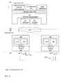
- FIG. 5 depicts a slot structure for a portion of a period.
- the slot structure depicts one frame 462 having a first and second channel 452 , where each channel has six time slots 452 .
- five of the time slots 452 of each channel i.e., Time Slots 1 - 5
- the sixth slot of each channel is an async slot, i.e., Time Slot 6 .
- the sync time slots are generally used for scheduled transmissions, e.g., slot transmissions.
- the async time slot is used for other unscheduled transmissions.
- An async time slot is used, for example, when a DT first starts up on a system (initial provisioning) and sends a message, using on-grid communications, to the FIM or other appropriate element(s) requesting a time slot assignment.
- the time slots are further described with respect to having a data burst portion 456 and an inter-burst interval 458 .
- the data burst portion 456 is approximately 5 seconds in length and the inter-burst interval is around 1 second, although different time allocations can be implemented, as is known.
- Channels 1 and 2 are depicted as having scheduled organization. Channel 1 is depicted has having designated DT HR 101 for Time Slot 1 , DT HR 102 for Time Slot 2 , DT HR 103 for Time Slot 3 , DT HR 104 for Time Slot 4 , DT HR 105 for Time Slot 5 , and async for Time Slot 6 .
- Channel 2 is depicted has having designated DT HR 201 for Time Slot 1 , DT HR 202 for Time Slot 2 , DT HR 203 for Time Slot 3 , DT HR 204 for Time Slot 4 , DT HR 205 for Time Slot 5 , and async for Time Slot 6 .
- DT HR 201 for Time Slot 1
- DT HR 202 for Time Slot 2
- DT HR 203 for Time Slot 3
- DT HR 204 for Time Slot 4
- DT HR 205 for Time Slot 5
- async for Time Slot 6 .
- FIG. 6 depicts a burst profile of a time slot of FIG. 5 in greater detail.
- the burst has a designed burst time, e.g., around 5 seconds, and a burst direction, e.g., beginning with the right side burst and ending with the left side of the burst.
- the burst profile can be broken into two component parts, e.g., a header and a tail.
- the header 472 of the data burst typically includes system information.
- the head, or header provides preamble data used by the computing system for Grid Location Awareness and demodulator synchronization.
- the header includes a characterizing signal that is used for detection by the FIM.
- the tail 474 of the data burst provides payload data, e.g., address data, control data, CRC data, voltage data, and/or other types of data.
- a plurality of time slots may be reserved for alerting (e.g., async messages), while other time slots are scheduled.
- a single channel is sufficient to permit 12,000 DTs to transmit once daily. It should be obvious to one skilled in the art, that the number of DTs, the periodicity of their scheduled transmissions, the number of available asynch slots, the size of the scheduled and asynch slots, and the number of required channels are all interrelated.
- the computer system can dynamically change what data a DT is providing. Moreover, if the amount of information being sent in a single transmission by a DT is decreased, then the periodicity can be increased. This is helpful in certain applications, such as detection of technical losses or non-technical losses (theft) or in rapidly detecting storm damage.
- a power company becomes aware of power loss based upon customers calling the power company the company to complain.
- the power company correlates the phone calls to a location(s) and sends a repair crew(s) to the identified location(s). Should a significant number of customers call, then the power company would likely investigate a higher level cause of the power outage, e.g., phase, feeder or substation failure. Conversely, a power company is generally not informed when customers' power is restored. As a result, a power company typically resorts to sending out workers to drive around and observe.
- a computer system using DTs in storm mode may not necessarily be concerned about the voltage level or other data typically collected and stored at the DT, only that the DT is transmitting, which would indicate that the DT still has power.
- This smaller amount of data translates to a smaller scheduled time slot, which in turn results in more slots during a period, and thus faster reporting by the DTs.
- something has failed—presumably due to weather.
- the presence and/or lack of transmissions by one or more DTs can be used for circuit failure inference.
- the computer system knows that time slot 222 , slot 235 , and slot 987 correspond to DTs on same circuit, and if the computer system is not receiving any information during those respective time slots from those devices, then the computer system can infer the entire circuit has failed. Quickly identifying circuit failure can lead to quicker system analysis and correction.
- the DT sends a message to the FIM which is forwarded to the concentrator system, or more specifically the network and data management component.
- the network and data management component determines a slot assignment for the DT that requested a slot assignment, records that slot assignment in a database, and forwards, using a downstream radio link or other appropriate method, that slot assignment downstream to the DT.
- the DT receives the slot assignment, it stores the slot assignment information in non-volatile memory and sends an acknowledgement signal back to the network and data management component, preferably through a upstream radio link.
- FIG. 7 A flowchart depicting the logical flow of the DT start up and slot assignment are depicted in FIG. 7 .
- segment S 200 the process starts. Process flow continues to segment S 202 .
- a DT begins to power up.
- the DT sends a message using an async channel of a Power grid communication system requesting slot timing information.
- Process flow continues to segment S 204 .
- segment S 204 the DT acquires slot timing information. Process flow continues to segment S 206 .
- segment S 206 the DT checks to see if the slot assignment information is stored in its persistent memory. If the slot assignment information is stored in persistent memory, then process flow continues to segment S 220 . If the slot assignment information is not stored in persistent memory, then process flow continues to segment S 208 .
- the DT transmits, preferably using on-grid communication mechanism, a provision request to an upstream processing system, e.g., the network and data management component by way of a substation receiver, preferably using an Async payload slot.
- an upstream processing system e.g., the network and data management component by way of a substation receiver, preferably using an Async payload slot.
- Process flow continues to segment S 210 .
- segment S 210 the DT starts a fixed retransmission timer plus random retransmission timer. Process flow continues to segment S 212 .
- segment S 212 the DT checks whether a slot assignment has been received, preferably through an RF link. If a slot assignment has been received, then process flow continues to segment S 216 . If a slot assignment has not been received, then process flow continues to segment S 214 .
- segment S 214 the DT checks to see if there is a timeout due to a fixed plus random time. If there is a timeout, process flow continues to segment S 208 . If there is not a timeout, process flow continues to segment S 212 .
- segment S 216 the DT stores the slot assignment in its persistent memory. Process flow continues to segment S 218 .
- segment S 218 the DT sends a signal acknowledging the receipt of the provision request, preferably by way of an upstream radio.
- Process flow continues to segment S 220 .
- segment S 220 the Routine exits and the process ends.
- a DT has requested and received its provision request for a slot assignment and has stored that information in its persistent memory.
- the process above is repeated for each slot assignment required.
- the data and network management component is tasked with managing the DTs, including providing, directly or indirectly, the provisioning information to each DT.
- DTs are provided with one or more slot assignment(s), e.g., Scheduled Payload Slot(s) assignment(s), for a given Frame and Slot on a pseudo-random basis.
- the first slot assignment is random, with the seed for the random number generator provided by the time of receipt of the Provisioning Request from the DT. After comparing the randomly generated first slot assignment with the data and network management component to see if the computed slot is already assigned, the process is repeated until an available slot is determined.
- multiple slot assignments are provided so as to schedule the slot assignments more or less equally throughout the time slot period, e.g., 24 hours, although the specific slot is still pseudo randomly generated.
- This pseudo random slot assignment methodology reduces the likelihood that when two circuits are folded on top of one another without a priori knowledge, the number of conflict in timing assignment is reduced and, in turn, the need and the required time for resolving the conflict is likewise reduced.
- the data and network management component receives provision requests from the DT via on-grid communications. It provides a slot assignment via the upstream and downstream RF link, although any appropriate communication systems can be employed for the slot assignment message.
- FIG. 8 is a flowchart depicting an exemplary logical flow of a methodology for assigning a slot for a DT that has provided a provision request.
- segment S 500 the provision process begins. Process flow continues to segment S 502 .
- segment S 502 a provision request from a DT is received by the data and network management component. This request is generally received by the data and network management component by way of the substation receiver, which in turn, received the request by way of on-grid communications. Process flow continues to segment S 504 .
- segment S 504 the data and network management component clears—resets—the Round_Trip_Timer and the Background_Task_Timer. Process flow continues to segment S 506 .
- segment S 506 the data and network management component, e.g., the VirtuGrid (VG), looks up, e.g., Num_Slots_DT, the DT to determine how slots, e.g., how many slots, are to be assigned to the DT. Process flow continues to segment S 508 .
- the data and network management component e.g., the VirtuGrid (VG)
- looks up e.g., Num_Slots_DT
- the DT determine how slots, e.g., how many slots, are to be assigned to the DT.
- Process flow continues to segment S 508 .
- an initial slot assignment e.g., Slot_Assigned
- f RAND1 Prov_Req_Time, Max_Slots, SD, ST
- SD the substation domain
- ST the substation transformer domain
- segment S 510 the slot assignment, e.g., Slot_Assigned, is reserved for the DT, e.g., in the VG.
- Process flow continues to segment S 512 .
- segment S 512 the data and network management component checks to see if the initial slot assignment is available. If the slot assignment is available then the process flow continues to segment S 516 . If the slot assignment is not available, then the process continues to segment S 514 .
- segment S 514 the slot assignment for the DT is released in the data and network management component. Process flow continues to segment S 508 .
- segment S 516 the slot assignment is provided to the DT, preferably using an RF link. Process flow continues to segment S 518 .
- segment S 518 the process waits until the system clock, or other timing mechanism reaches a predefined value for the Round_Trip clock. Process flow continues to segment S 520 .
- segment S 520 data and network management component checks to see if has received an provision acknowledgement signal from the DT. If the acknowledgement signal has been received, then process flow continues to segment S 522 . If the acknowledgement signal has not been received from the DT, then the process flow continues to segment S 526 .
- segment S 522 the data and network management component confirms in its database that the slot has been assigned to the DT. Process flow continues to segment S 524 .
- segment S 524 the data and network management component checks to see if the number of slots requested, e.g., Num_Slots_DT, for the DT is greater than one. If the number is greater than one, then the process flow continues to S 532 to assign additional slots to the DT. If the number not greater than one, then process flow continues to segment S 534 .
- the number of slots requested e.g., Num_Slots_DT
- segment S 526 the process waits until the system clock or other timing mechanism, reaches a predefined value for the Background_Task. Process flow continues to segment S 528 .
- segment S 528 data and network management component checks to see if there has been a new provision request received from the same DT. If there has been a new provision request received, then the process flow continues to segment S 530 . If there has not been a new provision request received then, the process flow continues to segment S 516 .
- segment S 530 data and network management component releases in its database the slot assigned for the DT. Process flow continues to segment S 504 .
- segment S 532 the system repeats this slot assignment methodology, or another slot assignment methodology, for example as described below with referenced to FIG. 9 , for each slot assignment needed greater than one.
- process flow continues to segment S 534 .
- segment S 534 the process exits and ends.
- the data and network management component has generated and provided a slot assignment(s) for a DT and received acknowledgement from the DT that it has received the slot assignment(s).
- FIG. 9 is a flowchart depicting an exemplary logical flow of a methodology for assigning a plurality of slots for a DT that has provided a provision request.
- segment S 602 the process to assign multiple slots to a DT starts. Process flow continues to segment S 604 .
- segment S 608 the (proposed) new slot assignment for the DT is set to the previously assigned slot plus an offset, e.g., N_Slot is set equal to N_Slot plus the Slot_Index.
- N_Slot is set equal to N_Slot plus the Slot_Index.
- segment S 610 the systems checks whether the number of slots is beyond the boundary of the allowable slot assignments, e.g., is N_Slot greater than the maximum number of a slot that can be assigned or N_Slot>Max_Slots? If N_Slot is greater, then process continues to segment S 612 . If N_Slot is not greater, then process flow continues to segment S 614 .
- the window size is the region of uncertainty around the next ideal slot assignment.
- segment S 616 data and network management component compares the proposed slot to the slot assignment database to determine if the proposed slot is available. If the proposed slot is available, then process flow continues to segment S 624 . If the proposed slot is not available, the process continues to S 614
- segment S 624 the proposed slot assignment, e.g., Slot_Assigned, is sent to the DT, preferably by way of a RF link.
- Process flow continues to segment S 622 .
- segment S 622 the data and network management component confirms in its database the slot assigned, e.g., Slot_Assigned, for the DT. Process flow continues to segment S 620 .
- segment S 620 the loop count is incremented. Process flow continues to segment S 618 .
- segment S 618 the loop count is compared to the number of slots needed for the DT, e.g., Loop_Count ⁇ Num_Slots_DT?. If the loop count is less than the number of slots needed, then the process flow continues to segment S 608 . If the loop count is not less than the number of slots needed then the process flow continues to segment S 626 .
- segment S 626 the system waits for a system clock or other timing mechanism to reach a predefined time, e.g., Background_Task seconds. Process flow continues to segment S 628 .
- segment S 628 data and network management component checks to see if acknowledgements, e.g., Provision_Ask, have been received for all of slots assigned to the DT. If all of the acknowledgement have been received then, process flow continues to S 632 . If not all of the acknowledgements have been received, then process flow continues to segment S 630 .
- acknowledgements e.g., Provision_Ask
- segment S 630 the data and network management component determines which slot assignment acknowledgement has not been received and provides the slot assignment(s) to the DT. Process flow continues to segment S 626 .
- segment S 632 the routine exits and the process ends.
- a slot conflict can occur when two or more DTs use the same Scheduled Payload Slot, e.g., a slot assignment, at substantially the same time.
- the slot conflict is typically caused by either an Unknown Event or a Rogue Transmitter.
- An Unknown Event is typically caused when the computer system makes or has made multiple assignments to the same scheduled payload slot. This typically occurs when the network and data management component assigns a particular payload slot to a first DT that located in a first domain of the distribution grid and to a second DT. At the time the network and data management component makes that assignment, the second DT is understood by the network and data management component to be in a domain other than the first domain.
- a slot conflict can also be caused by a rogue transmitter of a DT in the electric distribution grid.
- a DT includes internal circuitry that tracks master timing of the slot transmissions.
- time slotted transmission systems typically employ a universal timing synchronization signal that is periodically transmitted in a system to sync all of the units that send/receive on the system, generally referred to as a Master Sync. It is conceivable that a situation can arise where a DT's internal timing drifts off, and is no longer synchronized with the master timing. Lack of synchronization is typically caused by failure to update timing via NTP or Loss of GPS timing signal.
- the DT transmits its signal(s) at the appropriate time slot according to its internal timing however this time slot is not the appropriate time slot with respect to the master timing schedule.
- a Rogue Transmitter can “walk” its timing so as to create a single slot conflict, or span across two slots and create an adjacent slots conflict. DTs must obtain master timing on a periodic basis or are automatically squelched. If the signal is squelched, then the Rogue Transmitter's signal ceases to transmit, and the conflict likewise ceases to exist.
- a slot conflict is detected by examining the candidate signal energy that is received by the FIM during a time slot. This can be candidate signal energy over time or it can be an absence of candidate signal energy. Energy over time is the candidate signal energy that is received and is across substantially all of the time slot, partially across the time slot, and partially across adjacent time slots.
- Energy Across the Slot is when the FIM detects candidate signal energy across the slot, i.e., of a duration approximately equivalent to a DT transmission, then there is either a Slot Conflict or the presence of a large amount of impulse noise.
- Energy Partially Across the Slot is when the FIM detects candidate signal energy across a portion the slot, i.e., of a duration less than that of a DT transmission, then there is either a Rogue Transmitter Slot Conflict or the presence of some amount of impulse noise.
- Energy Partially Across Adjacent Slots is when the FIM detects candidate signal energy across a portion of two adjacent slots, then there is either a Rogue Transmitter Slot Conflict or the presence of some amount of impulse noise.
- candidate signal energy is substantially not detected at the FIM for an Assigned Slot, then no recognizable signal is received at that time slot.
- This lack of candidate signal energy suggests that a DT failed to transmit, the circuit powering the DT has failed, a condition on the Grid has attenuated the DT's transmit signal sufficiently to not be detected by the FIM, or the DT is transmitting at a time other than the assigned slot.
- the network and data management component initiates, at the earliest opportunity, a process for resolving the slot conflict.
- An exemplary method for resolving a time slot conflict generally depends on implied cause of the conflict, which is based on how the conflict was detected. If the conflict was detected based on Energy across a slot, then the network and data management component determines the DT that is the DT of record (i.e., the DT that the network and data management component believes should be transmitting at that time slot according to its database of assigned time slots) for that time slot, then the network and data management component determines a new assignable (not currently taken) payload slot for that DT and provides that payload slot information to the DT.
- candidate signal energy received at the time slot is examined, e.g., by the FIM, to determine if any information can be extracted. If a valid GLA signal—the header of the burst data—is extracted, then the network and data management component does not issue a new slot assignment.
- a new Assignable Payload Slot is given to the DT of Record (i.e., the DT that the network and data management component believes should be transmitting in this slot).
- FIG. 10 is a flowchart depicting a logical flow of a methodology for the decision process of whether to assign a new payload slot to a DT in the event that a network and data management component determines that there is a slot conflict.
- segment S 700 the new slot assignment decision process begins. Process flow continues to segment S 702 .
- segment S 702 the FIM has detected candidate signal energy has been detected during a valid slot time. Process flow continues to segment S 704 .
- segment S 706 the FIM examines the candidate signal energy received to determine whether a valid GLA signal has been detected. If a valid GLA signal has been detected, then the transmitted signal is likely a normal signal, where the conflict in transmission may be due to late noise or a rogue transmitter, but not likely; process flow continues to segment S 710 . If a valid GLA has not been received then this indicates that a collision is likely, which could have been caused by noise or by a rogue transmitter, but not likely; process flow continues to segment S 708 .
- segment S 708 a new assigned slot(s) is provided to the DT of record. Process flow continues to segment S 710 .
- segment S 710 the routine exits and the process ends.
- the network and data management component determines that a collision has occurred, then the DT of record is provided a new assigned time slot.
- the network and data management component stores the new assignment slot along with the DT within its system and the DT stores the assignment slot in its system.
- the computer system may employ one of several different approaches to reassigning slot assignments: in a situation with a DT having a single slot assignment, the computer system would typically use a Single Slot Reassignment approach; in a situation with a DT having a multiple slot reassignments, the computer system would typically use a Multi-Slot Reassignment approach; and in the situation where there is a conflicting DT, the computer system would typically employ a conflicting DT resolution approach.
- a DT with Single Scheduled Payload Slot In a preferred Single Slot Reassignment approach of the invention, also referred to as a DT with Single Scheduled Payload Slot, once a slot conflict has been identified, the conflict should be ideally resolved at the earliest reasonable time so that there will be a reduction or elimination of the likelihood that current and/or new information transmitted by a DT(s) in conflict will be lost, overwritten, or otherwise being inaccessible.
- the process should ensure that the new assigned time slot does not occur too close in time to the current, (e.g., old) assigned time slot as the system must account for some delays in providing the information to the DT and time for the DT to function. One part of the delay is for the system to determine what the new slot assignment should be for the DT of record.
- a second part of the delay is minimum amount of time needed to communicate the new slot assignment with the DT of record; this part of the delay would take into consideration, the traffic on the RF link used to transmit the new slot assignment.
- a third part of the delay although typically insignificant, is a delay for the DT to store the new assignment information and prepare to transmit the information during the new time slot. See, for example, FIG. 11 , which depicts a slot reassignment.
- a computer system detects a slot conflict in Frame 1 , slot 3 , denoted by an “X”, e.g., time slot 1162 . Shortly thereafter, the computer system determines a new slot assignment for the DT. There is a transmission delay—it isn't until the time corresponding to Frame 3 , slot 3 that the appropriate DT of record receives the slot assignment information, e.g., at time slot 1164 .
- the new slot assignment is Frame 4 , Slot 5 , e.g., time slot 1166 . Assuming that each slot is six seconds, the DT has approximately five time slots or thirty (30) seconds to prepare to transmit the information that it is supposed to transmit.
- the network and data management component upon Slot Conflict Detection, should initiate a process to reassign the slot assignment for the conflicted DT.
- the network and data management component identifies the conflicted DT.
- the network and data management component looks up what DT has been assigned to the slot with a conflict, which may be referred to as the “DT of Record.”
- the network and data management component seeks to give the DT of Record a pseudo random slot assignment within the range of a minimum offset, i.e., “No Assignment” period or “No Assignment Window” 1154 , and a maximum offset, i.e., Max Recovery.
- a “No Assignment” period allows sufficient time for the DT to receive the assignment message via the downstream radio link.
- the minimum No Assignment period is typically set based upon the type of downstream radio rink type, the outbound message queue time, and the upstream radio link type. In an approach, the no assignment period will be measured in seconds, but the system would typically avoid a No Assignment period being less than one Frame time or thirty (36) seconds for practical purposes. As such, a new slot assignment cannot within the time period covered by the No Assignment period.
- the computer system also employs a Max setoff, which is the maximum value, typically expressed in seconds, between the DT's slot assignment having a conflict and the newly proposed slot assignment for the DT.
- a Max setoff which is the maximum value, typically expressed in seconds, between the DT's slot assignment having a conflict and the newly proposed slot assignment for the DT.
- the DT After receiving the new assigned slot, the DT acknowledges the slot assignment over the upstream radio link.
- the DT stores the new slot assignment, and updates its circuitry appropriately to transmit at the new slot assignment.
- FIG. 12 is a flowchart depicting a logical flow of a methodology for a single slot reassignment according to a preferred approach of the invention. As described above, when the computer system determines that a DT having a single slot assignment has a conflict and needs to be reassigned, then the computer system implements the following approach:
- segment S 1102 the single slot reassignment process begins. Process flow continues to segment S 1102 .
- N_Slot is set approximately equal to the current slot of the DT in conflict plus an offset the value of the No Assignment window, e.g., No_Assign_Window. Process flow continues to segment S 1106 .
- segment S 1106 the proposed slot assignment seed is compared to the maximum number of slots available, e.g., Max_Slots. If the proposed slot assignment number is greater than Max_Slots, then process flow continues to segment S 1108 . Otherwise, process flow continues to S 1110 .
- segment S 1112 the network and data management component of the computer system checks its database to see whether the proposed assignment slot is available. If the proposed assignment slot is available, then process flow continues to segment S 1114 . Otherwise, process flow continues to S 1110 .
- segment S 1114 the network and data management component records the proposed slot assignment, e.g., Slot_Assigned, for the DT in its database. Process flow continues to segment S 1116 .
- the proposed slot assignment e.g., Slot_Assigned
- a loop counter (i.e., Loop_Count) is set to zero. Process flow continues to segment S 1118 .
- segment S 1118 the loop counter is incremented by one. Process flow continues to segment S 1120 .
- segment S 1120 the loop counter is compared to a defined number for the max number of attempts to communicate the new assigned slot to the DT, e.g., Loop_Count>Max_Retries? If the loop counter is greater than the Max number of retries, then process flow continues to S 1128 . Otherwise, process flow continues to segment S 1122 .
- Segment S 1122 the computer systems send the proposed slot assignment, e.g., Slot_Assigned, to the DT, preferably via RF link.
- Process flow continues to segment S 1124 .
- segment S 1124 the system waits for a defined amount of time, e.g., Round_Trip_Seconds. When the delay is over, process flow continues to segment S 1126 .
- a defined amount of time e.g., Round_Trip_Seconds.
- segment S 1126 the computer system checks to see if an acknowledgement has been received from the DT that the slot assignment, more specifically a slot reassignment, has been received from the DT, e.g., Slot_Reassign_Ack. If an acknowledgement has been received, then process flow continues to segment S 1132 . If not, the process flow continues to S 1118 .
- segment S 1128 the computer system releases the proposed slot assignment which can be used by the system for future use. Process flow continues to segment S 1130 .
- segment S 1130 the Routine exits and the process ends.
- segment S 1132 the computer stores confirmation of the proposed slot assignment as the slot assignment for the DT. Process flow continues to segment S 1130 .
- the DT is provided with a new slot assignment, where the slot assignment should be far enough in the future that the DT will have time to transmit its data at the new slot assignment. If the process ends because it has tried too many times, then the DT is not reprogrammed at this time.
- a Reassignment approach for a DT with two or more Scheduled Payload Slots also referred to as a Multi-Slot Reassignment
- the computer system typically applies a combination of methods.
- a first slot reassignment is done according to DT of Record is given the first slot assignment using the procedure of “DT with Single Assignable Payload Slot” as discussed above with reference to FIG. 12 .
- the remainder of slot assignments are provided generally using the procedure of “Initial DT Detection and Assignment” as discussed above with reference to FIGS. 7, 8 and 9 for the remaining assignment slots of the DT having a plurality of assignment slots.
- FIG. 13 is a flowchart depicting a logical flow of a methodology for a multiple slot reassignment. As described above, when the computer system determines that a DT having a slot assignment has a conflict and needs to be reassigned, then the computer system implements the following in a preferred approach.
- segment S 1200 the process starts. Process flow continues to segment S 1202 .
- segment S 1202 the single slot reassignment process begins. Process flow continues to segment S 1204 .
- segment S 1204 the proposed slot assignment N_Slot seed is set approximately equal to the current slot of the DT, e.g., DT_Slot, plus the value of an offset to account of delay, e.g., the No_Assign_Window. Process flow continues to segment S 1206 .
- segment S 1206 the proposed slot assignment seed, e.g., N_Slot, is compared to the maximum number of slots available. If the proposed slot assignment number is greater than Max_Slots, then Process flow continues to segment S 1208 . Otherwise, process flow continues to S 1210 .
- the proposed slot assignment seed e.g., N_Slot
- segment S 1212 the network and data management component checks its database to see whether the proposed assignment slot is available. If the proposed assignment slot is available, then process flow continues to segment S 1214 . Otherwise, process flow continues to S 1210 .
- segment S 1214 the network and data management component records the proposed slot assignment for the DT in its database. Process flow continues to segment S 1216 .
- segment S 1227 if N_Slot greater than the maximum number of slots that can be assigned, e.g., N_Slot>Max_Slots? If N_Slot is greater, then process continues to segment S 1224 . If N_Slot is not greater, then process flow continues to segment S 1226 .
- segment S 1234 the data and network management component compares the slot to the slot assignment database to determine if slot is available. If the slot is available, then process flow continues to segment S 1232 . If the slot is not available, the process continues to S 1226 .
- segment S 1232 the data and network management component reserves the slot assignment, e.g., Slot_Assigned, for the DT in its database, e.g., the VG. Process continues to segment S 1230 .
- slot assignment e.g., Slot_Assigned
- segment S 1228 the loop count is compared to the number of slots need for the DT, e.g., Loop_Count ⁇ Num_Slots_DT. If the loop count is less than the number of slots needed, then the process flow continues to segment S 1220 . If the loop count is not less than the number of slots needed then the process flow continues to segment S 1236 .
- segment S 1236 the Loop_Count is set to zero. Process flow continues to segment S 1238 .
- the Loop_Count is compared to the maximum number of retries (Max_Retries). If Loop_Count is greater than the Max_Retries, e.g., Loop_Count>Max_Retries?, then the process flow continues to S 1242 . Otherwise the process flow continues to segment S 1244 .
- segment S 1242 all of the proposed slot assignments, e.g., Slot_Assigned, for the DT are released. Process flow continues to segment S 1252 .
- segment S 1244 all of the proposed slot assignments for the DT are sent to the DT, preferably via RF link. Process flow continues to segment S 1246 .
- segment S 1246 the system waits for a system clock or other timing mechanism to reach a predefined time of Round_Trip seconds. Process flow continues to segment S 1248 .
- segment S 1248 the data and network management component checks to see if acknowledgements have been received for all of slots assigned to the DT, e.g., Slot_Reassign_Ack received?. If all of the acknowledgements have been received then, process flow continues to S 1250 . If not all of the acknowledgements have been received, then process flow continues to segment S 1238 .
- segment S 1250 the data and network management component confirms in its database all of slots assigned to the DT. Process flow continues to segment S 1252
- segment S 1252 the Routine exits and the process ends.
- the computer system detects the conflicting DT when the conflicting DT transmits at the next allotted time slot, which, on a 24 hour period, will be approximately 24 hours after the last allotted time slot.
- the computer system can determine the DT's location on the grid based on its established techniques. See, for example, “System And Method For Inferring Schematic And Topological Properties Of An Electrical Distribution Grid”, U.S. patent application Ser. No. 13/871,944 and “System And Methods For Inferring The Feeder And Phase Powering An On-Grid Transmitter” U.S. patent application Ser. No. 14/304,648, the contents of which are incorporated herein in their entirety.
- the computer system can determine an ID of the conflicting DT based on information that it transmits.
- the conflicting DT transmit identifying information for itself as part of a scheduled signal transmission, as the DT's identifying information is contained as part of the data burst ( FIG. 6 ), which may be part of the header and/or the tail of the data burst.
- the computer system sends a signal to the conflicting DT directing it to send its identifying information during its next scheduled transmission.
- a computer system may infer which DT is the conflicting DT if it reviews which DTs it has received a transmission from.
- the computer system can infer that this is the conflicting DT and send an instruction to that DT to have it send its identifying information during its next schedule transmission. If the computer systems receives a DT's identifying information during the next time slot corresponding to the conflicting time slot, then that identifying information is presumed to be the conflicting DT. If the computer system finds that there are several DTs that do not seem to have transmitted a signal, then the computer system can interactively go through each missing DT sending instructions to each until the identifying information is received during the conflicting time slot or until there are no DTs with missing transmission remaining.
- the computer system can send instructions to all of the DTs in the domain indicating that during the next period of signal transmissions, each DT is to transmit its identifying information.
- the first two approaches could generally be sent via a downstream RF link directed at a specific DT, in this approach, the computer system would employ an on-grid transmission and/or a downstream RF link to all of the DTs to increase the likelihood that the conflicting DT will receive the transmission.
- the computer system determines a DT's ID from a transmission signal, updates its database to reflect that the conflicting DT associated with the conflicting DT's ID is transmitting at the conflicting time slot.
- FIG. 14 is a flowchart depicting a logical flow of a methodology for resolving the conflict in transmissions between two DTs.
- the computer system determines the identification of the conflicting DT, then the computer system updates its database to reflect the conflicting slot allotment time to be that of the conflicting DT.
- the computer system implements the following in a preferred approach to update the computer system's database information:
- segment S 1300 the conflicting DT resolution process begins. Process flow continues to segment S 1302 .
- segment S 1302 the Conflicting DT is detected, e.g., most likely during the next time corresponding to the assigned slot, which is typically 24 hours later, when it again transmits.
- Process flow continues to segment S 1304 .
- the computer system determines the ID of the conflicting DT and provides it to the computer system, e.g., the network and data management component of the computer system, for lookup.
- the ID of the conflicting DT is determined by identification of the DT.
- the conflicting DT is determined based on a combination of the feeder and phase that the computer system, most likely the FIM, has associated with the signal received from the conflicting DT and some portion of information in the header or payload data of the signal.
- the computer system also tracks the location of the conflicting DT. Process flow continues to segment S 1306 .
- segment S 1306 the computer system's database, e.g., VG, is updated to reflect the conflicting DT to transmit at the conflicting slot allotment time and the location of the conflicting DT.
- Process flow continues to segment S 1308 .
- segment S 1308 the Routine exits and process ends.
- the conflicting DT has been identified and the computer system's database has been updated to reflect the conflicting DT's slot allotment and its location.
- the occasion may arise when a DT should have a new slot allotment.
- the occasion could be, for example, due to a conflict, as described above, or the occasion could be for some other reason.
- the computer system Once the computer system has determined that a DT should be reassigned to a different time slot(s), it will reserve a new slot(s) for the DT and send that new slot(s) information to the DT. After the computer system receives acknowledgement of receipt back from the DT, the computer system updates its database to reflect the slot assignments for the DT.
- the computer system determines the conflicting DT by looking at signals received from DTs on the grids.
- the computer system tracks when the last signal has been received from each DT. Therefore, the computer system can determine which, if any, DTs that are scheduled to transmit, e.g., they have at least one slot assignment, but the computer system has not received any signals from them for at least some time, e.g. one period. If there is only one DT from which there has been no signal received for some time, then the computer system assumes that this the DT in conflict.
- the computer system can iteratively process each of these DTs assuming that it is the DT in conflict, and reassign slot assignments for each.
- the computer system will work reassigning DTs iteratively through only some of the DTs without a recent signal until some stopping point is reached (and the computer system can resume reassigning DTs that have not been recently heard from). For example, the computer system will stop after a fixed number of DTs are reassigned.
- the computer system will stop reassigning DTs when the time slot that had candidate signal energy received but no identifiable signal has changed, and now the time slot either has an identifiable signal or the time slot does not have candidate signal energy sufficient to suggest that a DT device transmitted during that time.
- FIG. 15 is a flowchart depicting a logical flow of a methodology for resolving the conflicting DT in accordance with a preferred approach of the invention.
- the computer system determines the identification of the conflicting DT, then the computer system updates its database to reflect the conflicting slot allotment time to be that of the conflicting DT.
- the computer system implements the following in a preferred approach:
- segment S 1402 the Intentional Reassignment process begins. Process flow continues to segment S 1404 .
- segment S 1404 the network and data management component reserves a slot(s) for the DT.
- the component preferably uses one of the methods described above to assign slot(s) for the DT, or any other appropriate method.
- Process flow continues to segment S 1406 .
- a counter, Loop_Count is set to zero. Process flow continues to segment S 1408 .
- segment S 1410 the counter is compared to Max_Retries, the max number of retries for waiting for acknowledgement from the DT, e.g., Loop_Count>Max_Retries?. If the counter is less than Max_Retries, then process flow continues to segment S 1412 . Otherwise, process flow continues to segment S 1420 .
- segment S 1412 the computer system causes the slot assignment(s), e.g., Slot_Assigned, to be sent to the DT, preferably by way of an RF link.
- Process flow continues to segment S 1414 .
- segment S 1414 the system waits for a system clock or other timing mechanism to reach a predefined time of Round_Trip seconds. Process flow continues to segment S 1416 .
- segment S 1416 the system checks whether it has received an acknowledgment of slot assignments being received from the DT. If an acknowledgement has been received, the process flow continues to segment S 1418 . Otherwise, process flow continues to segment S 1408 .
- segment S 1418 the network and data management component confirms that the reserved slot(s), e.g., Slot_Assigned, for the DT are assigned to the DT. Process flow continues to segment S 1422 .
- the reserved slot(s) e.g., Slot_Assigned
- segment S 1422 the process exits and ends.
- segment S 1420 the computer system releases all of the reserved slots for the DT in the database. Process flow continues to segment S 1422 .
- the DT has been assigned a new time slot(s).
- the slot assignment(s) for the DT is stored in the DT and in the computer system.
- the algorithm(s) are relatively simple, which would suggest that the algorithms are relatively simple to employ, modify, if needed, and maintain.
- the invention can be employed to introduce or modify DT operation without or with a priori knowledge of the circuit topology.
- the invention can be employed to introduce or modify a DT.
- the invention can be employed to resolve circuit fold-overs without increase of time or complexity, essentially without regard to the size of the fold-over.
- Fifth, employment of the invention supports recovery of information in a timely manner.
- Sixth employment of the invention is compatible with, but does not require, a priori knowledge of movement of DTs.
- Seventh employment of the invention can be used without a priori assignment of initial slot assignments.
- Eighth employment of the invention is False Positive Tolerant.
- Ninth employment of the invention does not add traffic to async payload slots.
Abstract
Description
Claims (20)
Priority Applications (1)
| Application Number | Priority Date | Filing Date | Title |
|---|---|---|---|
| US14/928,783 US10079765B2 (en) | 2014-10-30 | 2015-10-30 | System and methods for assigning slots and resolving slot conflicts in an electrical distribution grid |
Applications Claiming Priority (2)
| Application Number | Priority Date | Filing Date | Title |
|---|---|---|---|
| US201462072882P | 2014-10-30 | 2014-10-30 | |
| US14/928,783 US10079765B2 (en) | 2014-10-30 | 2015-10-30 | System and methods for assigning slots and resolving slot conflicts in an electrical distribution grid |
Publications (2)
| Publication Number | Publication Date |
|---|---|
| US20160127242A1 US20160127242A1 (en) | 2016-05-05 |
| US10079765B2 true US10079765B2 (en) | 2018-09-18 |
Family
ID=55853942
Family Applications (1)
| Application Number | Title | Priority Date | Filing Date |
|---|---|---|---|
| US14/928,783 Expired - Fee Related US10079765B2 (en) | 2014-10-30 | 2015-10-30 | System and methods for assigning slots and resolving slot conflicts in an electrical distribution grid |
Country Status (12)
| Country | Link |
|---|---|
| US (1) | US10079765B2 (en) |
| EP (1) | EP3213421B1 (en) |
| JP (1) | JP2017532947A (en) |
| CN (1) | CN107005273B (en) |
| AU (1) | AU2015338943B2 (en) |
| BR (1) | BR112017009036A2 (en) |
| CA (1) | CA2964365A1 (en) |
| CL (1) | CL2017001038A1 (en) |
| CO (1) | CO2017004899A2 (en) |
| MX (1) | MX361841B (en) |
| PE (1) | PE20171123A1 (en) |
| WO (1) | WO2016070104A1 (en) |
Families Citing this family (19)
| Publication number | Priority date | Publication date | Assignee | Title |
|---|---|---|---|---|
| CA2870452C (en) | 2011-04-15 | 2020-03-10 | Dominion Energy Technologies, Inc. | System and method for single and multi zonal optimization of utility services delivery and utilization |
| US9059842B2 (en) | 2011-06-09 | 2015-06-16 | Astrolink International Llc | System and method for grid based cyber security |
| WO2013020053A1 (en) | 2011-08-03 | 2013-02-07 | Power Tagging Technologies, Inc. | System and methods for synchronizing edge devices on channels without carrier sense |
| US10097240B2 (en) | 2013-02-19 | 2018-10-09 | Astrolink International, Llc | System and method for inferring schematic and topological properties of an electrical distribution grid |
| CA2915072A1 (en) | 2013-06-13 | 2014-12-18 | Astrolink International Llc | Inferring feeder and phase powering a transmitter |
| WO2014201348A1 (en) | 2013-06-13 | 2014-12-18 | Astrolink International Llc C/O Lockheed Martin Corporation | Non-technical losses in a power distribution grid |
| CN107003346B (en) | 2014-10-30 | 2019-10-25 | 艾斯通林克国际有限责任公司 | System, the method and apparatus of grid position |
| US10650688B1 (en) * | 2016-07-22 | 2020-05-12 | Rockwell Collins, Inc. | Air traffic situational awareness using HF communication |
| CN106302005A (en) * | 2016-08-04 | 2017-01-04 | 国电南瑞科技股份有限公司 | The method of combining unit device dynamic monitoring IEC61850 92 network storm |
| EP3744056A4 (en) * | 2018-01-26 | 2021-10-20 | Opanga Networks, Inc. | Systems and methods for identifying candidate flows in data packet networks |
| WO2019180273A1 (en) * | 2018-03-23 | 2019-09-26 | Electricity North West Property Limited | System for frequency regulation on a power distribution network |
| CN109274414B (en) * | 2018-07-26 | 2021-07-09 | 厦门大学 | Method for network coding and edge cache to cooperate in multi-direction wireless relay interaction channel |
| EP3629438A1 (en) * | 2018-09-26 | 2020-04-01 | Siemens Aktiengesellschaft | Method and a device for determining the network state of a low voltage network of an energy supply system |
| MX2021004395A (en) * | 2018-10-19 | 2021-06-04 | Valmont Industries | System and method for detecting and identifying power line carrier controlled devices within an irrigation system. |
| CN109506669B (en) * | 2018-12-28 | 2021-10-08 | 斑马网络技术有限公司 | Dynamic path planning method, device, system and storage medium |
| CN111600647B (en) * | 2020-05-22 | 2021-07-06 | 上海航天电子通讯设备研究所 | System and method for detecting collision energy of satellite-borne AIS signal multiple time slots |
| CN114095059B (en) * | 2020-08-24 | 2022-12-06 | 华为技术有限公司 | Power line communication method, device and system |
| EP4277436A1 (en) * | 2021-01-07 | 2023-11-15 | Beijing Xiaomi Mobile Software Co., Ltd. | Capability sending method and apparatus, and capability receiving method and apparatus |
| TWI812370B (en) * | 2022-07-28 | 2023-08-11 | 行政院原子能委員會核能研究所 | Real-time display device and method for the operation state of a power grid feeder |
Citations (271)
| Publication number | Priority date | Publication date | Assignee | Title |
|---|---|---|---|---|
| US3733586A (en) | 1972-03-14 | 1973-05-15 | Gen Public Utilities | Meter interrogation system having strobe logic control |
| US3911415A (en) | 1973-12-18 | 1975-10-07 | Westinghouse Electric Corp | Distribution network power line carrier communication system |
| US3942170A (en) | 1975-01-31 | 1976-03-02 | Westinghouse Electric Corporation | Distribution network powerline carrier communication system |
| US3944723A (en) | 1974-12-05 | 1976-03-16 | General Electric Company | Station for power line access data system |
| US4200770A (en) | 1977-09-06 | 1980-04-29 | Stanford University | Cryptographic apparatus and method |
| US4361766A (en) | 1979-10-24 | 1982-11-30 | Enertec | Remotely-controllable relays |
| US4371867A (en) | 1977-08-25 | 1983-02-01 | Lgz Landis & Gyr Zug Ag | Transmitting signals over alternating current power networks |
| US4568934A (en) | 1981-06-09 | 1986-02-04 | Adec, Inc. | Computer controlled energy monitoring system |
| US4580276A (en) | 1983-08-05 | 1986-04-01 | Consultant's Choice Inc. | System and method for transporting data |
| US4633463A (en) | 1984-03-28 | 1986-12-30 | Canadian Marconi Corporation | Radio communication system |
| US4668934A (en) | 1984-10-22 | 1987-05-26 | Westinghouse Electric Corp. | Receiver apparatus for three-phase power line carrier communications |
| JPH01106652A (en) | 1987-10-20 | 1989-04-24 | Fujitsu Ltd | Data collection system |
| US4918422A (en) | 1988-04-25 | 1990-04-17 | Emerson Electric Co. | Method and apparatus for extracting inbound information generated line-to-line in a multi-phase electric distribution system |
| EP0395495A1 (en) | 1989-04-27 | 1990-10-31 | SCHLUMBERGER INDUSTRIES, INC. (a Delaware corporation) | Adaptive network routing for power line communications |
| EP0629098A2 (en) | 1993-05-17 | 1994-12-14 | Logica Uk Limited | Domestic meter |
| WO1995001030A1 (en) | 1993-06-25 | 1995-01-05 | Remote Metering Systems Ltd. | Mains signalling systems |
| US5463624A (en) * | 1994-04-15 | 1995-10-31 | Dsc Communications Corporation | Bus arbitration method for telecommunications switching |
| JPH09501766A (en) | 1993-06-25 | 1997-02-18 | リモート・メタリング・システムズ・リミテッド | Phase determination of commercial power supply |
| WO1998006187A1 (en) | 1996-08-06 | 1998-02-12 | Northern Telecom Limited | Power line communications |
| US5812557A (en) | 1993-04-02 | 1998-09-22 | Echelon Corporation | Power line communications analyzer |
| US5818725A (en) | 1993-08-11 | 1998-10-06 | First Pacific Networks | System for utility demand monitoring and control |
| US5987305A (en) | 1995-12-08 | 1999-11-16 | Siemens Aktiengesellschaft | System and method for automatically setting up a radio link for transmitting data between two or more transmitter/receiver stations |
| US6144292A (en) | 1992-10-22 | 2000-11-07 | Norweb Plc | Powerline communications network employing TDMA, FDMA and/or CDMA |
| US6212560B1 (en) | 1998-05-08 | 2001-04-03 | Compaq Computer Corporation | Dynamic proxy server |
| US20010018561A1 (en) | 2000-02-29 | 2001-08-30 | Tanita Corporation | Compact type of living body variable measuring device |
| US20010037378A1 (en) | 2000-03-21 | 2001-11-01 | Sony Corporation | Information processing apparatus, information processing method, information processing system and recording medium |
| US20010055272A1 (en) | 1999-12-20 | 2001-12-27 | Kazuyoshi Matsuno | Digital signal transmission apparatus |
| US6366062B2 (en) | 1997-12-08 | 2002-04-02 | Microplanet, Inc. | Method and apparatus for electronic power control |
| US6373399B1 (en) | 1990-02-15 | 2002-04-16 | Itron, Inc. | Wide area communications network for remote data generating stations |
| US20020069299A1 (en) | 2000-12-01 | 2002-06-06 | Rosener Douglas K. | Method for synchronizing clocks |
| US20020089927A1 (en) | 2001-01-11 | 2002-07-11 | Fischer Michael A. | System and method for synchronizing data trasnmission across a variable delay interface |
| US6535797B1 (en) | 2000-02-01 | 2003-03-18 | Spectrum Engineering Corporation | Electrical distribution system and method of monitoring and/or controlling same |
| US20030098671A1 (en) | 2001-11-26 | 2003-05-29 | Visteon Global Technologies, Inc. | Anti-islanding detection scheme for distributed power generation |
| US20030151491A1 (en) | 2000-04-19 | 2003-08-14 | Fabrice Martin | Method and device for monitoring enablement of an electrical apparatus connected to a power grid |
| JP2003259696A (en) | 2002-02-28 | 2003-09-12 | Jfe Engineering Kk | Generation control method and program thereof |
| JP2003258689A (en) | 2002-02-27 | 2003-09-12 | Sumitomo Electric Ind Ltd | Power-line carrier communication system and modem for power-line carrier communication |
| US6650249B2 (en) | 1998-05-01 | 2003-11-18 | Elster Electricity, Llc | Wireless area network communications module for utility meters |
| JP2003339120A (en) | 2002-05-17 | 2003-11-28 | Sumitomo Electric Ind Ltd | Utilization method and receiving system for secondary battery |
| JP2004015840A (en) | 2002-06-03 | 2004-01-15 | Mitsubishi Electric Corp | Distribution system exploration system and distribution system exploration arrangement |
| US6687110B2 (en) | 2000-04-05 | 2004-02-03 | Nu-Lec Industries Pty Limited | Isolating circuit breaker and circuit protection arrangement |
| US6690655B1 (en) | 2000-10-19 | 2004-02-10 | Motorola, Inc. | Low-powered communication system and method of operation |
| US20040062267A1 (en) | 2002-03-06 | 2004-04-01 | Minami John Shigeto | Gigabit Ethernet adapter supporting the iSCSI and IPSEC protocols |
| JP2004147063A (en) | 2002-10-24 | 2004-05-20 | Global Com:Kk | Broadcast system and light bulb |
| US6747994B2 (en) | 2001-10-17 | 2004-06-08 | Qualcomm, Incorporated | Selecting optimal transmit formats for transmissions over allocated time durations |
| US20040110044A1 (en) | 2001-03-15 | 2004-06-10 | Hydrogenics Corporation | System and method for enabling the real time buying and selling of electricity generated by fuel cell powered vehicles |
| US6788702B1 (en) * | 1999-10-15 | 2004-09-07 | Nokia Wireless Routers, Inc. | Protocol for neighborhood-established transmission scheduling |
| US20040184406A1 (en) | 2003-03-17 | 2004-09-23 | Sony Corporation And Sony Electronics, Inc. | Network bandwidth management |
| US20040218688A1 (en) | 2002-06-21 | 2004-11-04 | John Santhoff | Ultra-wideband communication through a power grid |
| US20040227621A1 (en) | 2000-04-14 | 2004-11-18 | Cope Leonard D. | Power line communication apparatus and method of using the same |
| US20040226621A1 (en) | 2002-03-01 | 2004-11-18 | Honeywell Normalair-Garrett (Holdings) Limited | Gas supply apparatus |
| US20050005150A1 (en) | 2003-06-26 | 2005-01-06 | International Business Machines Corporation | Apparatus and method for location specific authentication using powerline networking |
| US20050017848A1 (en) | 2003-07-24 | 2005-01-27 | Hunt Technologies, Inc. | Endpoint receiver system |
| US20050018766A1 (en) | 2003-07-21 | 2005-01-27 | Sony Corporation And Sony Electronics, Inc. | Power-line communication based surveillance system |
| US20050043860A1 (en) | 2001-08-15 | 2005-02-24 | Petite Thomas D. | System and method for controlling generation over an integrated wireless network |
| US20050047379A1 (en) | 2003-08-29 | 2005-03-03 | Sony Corporation | Ultra-wide band wireless / power-line communication system for delivering audio/video content |
| US20050063422A1 (en) | 2003-09-19 | 2005-03-24 | Sashi Lazar | Communication protocol over power line communication networks |
| US20050144437A1 (en) | 1994-12-30 | 2005-06-30 | Ransom Douglas S. | System and method for assigning an identity to an intelligent electronic device |
| JP2005252671A (en) | 2004-03-04 | 2005-09-15 | Casio Comput Co Ltd | Ofdm signal demodulating device and method |
| US20050207079A1 (en) | 2004-03-17 | 2005-09-22 | Tiller David S | System and apparatus for a multifunctional powerline carrier device with data management and power surge protector |
| US6961641B1 (en) | 1994-12-30 | 2005-11-01 | Power Measurement Ltd. | Intra-device communications architecture for managing electrical power distribution and consumption |
| US20050253690A1 (en) | 2001-10-02 | 2005-11-17 | Telkonet Communications, Inc. | Method and apparatus for attaching power line communications to customer premises |
| US20050281326A1 (en) | 2004-06-18 | 2005-12-22 | Hong Yu | Transceiver apparatus and method having ethernet-over-power and power-over-ethernet capability |
| US20060071757A1 (en) * | 2004-09-24 | 2006-04-06 | Burghard Brion J | Communication methods, systems, apparatus, and devices involving RF tag registration |
| US20060078044A1 (en) | 2004-10-11 | 2006-04-13 | Norrell Andrew L | Various methods and apparatuses for imulse noise mitigation |
| US20060091877A1 (en) | 2004-10-19 | 2006-05-04 | Robinson Andrew J | Method and apparatus for an electric meter |
| US20060097573A1 (en) | 2004-10-26 | 2006-05-11 | Gidge Brett D | Power line communications system and method of operating the same |
| US7053756B2 (en) | 2001-12-21 | 2006-05-30 | Current Technologies, Llc | Facilitating communication of data signals on electric power systems |
| US7058524B2 (en) | 2002-10-25 | 2006-06-06 | Hudson Bay Wireless, Llc | Electrical power metering system |
| US7069117B2 (en) | 2002-04-01 | 2006-06-27 | Programmable Control Services, Inc. | Electrical power distribution control systems and processes |
| US7076378B1 (en) | 2002-11-13 | 2006-07-11 | Current Technologies, Llc | Device and method for providing power line characteristics and diagnostics |
| US20060152344A1 (en) | 2002-12-07 | 2006-07-13 | Mowery Richard A Jr | Powerline Communication Network Handoff |
| JP2006262570A (en) | 2005-03-15 | 2006-09-28 | Tokyo Electric Power Co Inc:The | Power supply system |
| US20060259199A1 (en) | 2003-06-05 | 2006-11-16 | Gjerde Jan O | Method and a system for automatic management of demand for non-durables |
| US20060291575A1 (en) | 2003-07-03 | 2006-12-28 | Berkman William H | Power Line Communication System and Method |
| US20070047573A1 (en) | 2005-08-29 | 2007-03-01 | Arkados, Inc. | Networking and multimedia adapter for power outlets |
| US7188003B2 (en) | 1994-12-30 | 2007-03-06 | Power Measurement Ltd. | System and method for securing energy management systems |
| US7194528B1 (en) | 2001-05-18 | 2007-03-20 | Current Grid, Llc | Method and apparatus for processing inbound data within a powerline based communication system |
| US20070076650A1 (en) * | 2005-09-30 | 2007-04-05 | Arati Manjeshwar | System and method for a communication protocol for wireless sensor systems including systems with high priority asynchronous message and low priority synchronous message |
| US20070100506A1 (en) | 2005-10-31 | 2007-05-03 | Ralph Teichmann | System and method for controlling power flow of electric power generation system |
| US20070101438A1 (en) | 2005-10-28 | 2007-05-03 | Gunasekaran Govindarajan | Location-based authentication |
| US20070114987A1 (en) | 2005-10-28 | 2007-05-24 | Electro Industries/Gauge Tech. | Intelligent electronic device for providing broadband Internet access |
| US7236765B2 (en) | 2003-07-24 | 2007-06-26 | Hunt Technologies, Inc. | Data communication over power lines |
| US20070162550A1 (en) | 2006-01-06 | 2007-07-12 | Outland Research, Llc | Vehicle-to-vehicle instant messaging with locative addressing |
| JP2007185083A (en) | 2005-12-06 | 2007-07-19 | Toyota Motor Corp | Charging system and electric vehicle |
| US7251570B2 (en) | 2003-07-18 | 2007-07-31 | Power Measurement Ltd. | Data integrity in a mesh network |
| US20070208521A1 (en) | 2001-08-09 | 2007-09-06 | Hunt Technologies, Llc | System for controlling electrically-powered devices in an electrical network |
| US20070211401A1 (en) | 2006-03-08 | 2007-09-13 | Distribution Control Systems | Intelligent fault detector system and method |
| US7280931B1 (en) | 2006-05-18 | 2007-10-09 | International Business Machines Corporation | Method and system for calibrating an electrical device |
| US20070237181A1 (en) | 2004-07-29 | 2007-10-11 | Woungsik Cho | Method and System for Generating Switching Timing Signal for Separating Transmitting and Receiving Signal in Optical Repeater of Mobile Telecommunication Network Using Tdd and Ofdm Modulation |
| US20070247331A1 (en) | 2006-03-31 | 2007-10-25 | Bruce Angelis | Integrated data collection, anomaly detection and investigation, such as integrated mobile utility meter reading, theft detection and investigation system |
| US20070271383A1 (en) | 2006-05-18 | 2007-11-22 | International Business Machines Corporation | Method and system for managing an electrical device over a power delivery network |
| US20070297425A1 (en) | 2006-06-23 | 2007-12-27 | George Chirco | Systems and methods for establishing a network over a substation dc/ac circuit |
| US7319280B1 (en) | 2007-04-24 | 2008-01-15 | Telkonet, Inc. | Power line coupler adapted for use with multiple communication systems using different frequency spectra |
| US7323968B2 (en) | 2005-12-09 | 2008-01-29 | Sony Corporation | Cross-phase adapter for powerline communications (PLC) network |
| US20080040479A1 (en) | 2006-08-10 | 2008-02-14 | V2 Green Inc. | Connection Locator in a Power Aggregation System for Distributed Electric Resources |
| US20080057866A1 (en) | 2006-08-24 | 2008-03-06 | Sony Deutschland Gmbh | Method for transmitting a signal on a power line network, transmitting unit, receiving unit and system |
| EP1901145A2 (en) | 2006-08-23 | 2008-03-19 | MicroNet Sensorik GmbH | Field device and method of operating the same |
| JP2008098812A (en) | 2006-10-10 | 2008-04-24 | National Institute Of Advanced Industrial & Technology | Ofdm transmission method and ofdm transmitter |
| US7369579B2 (en) | 2002-09-25 | 2008-05-06 | Oleg Logvinov | Method and system for timing controlled signal transmission in a point to multipoint power line communications system |
| US20080109387A1 (en) | 2006-11-02 | 2008-05-08 | Deaver Brian J | Power Theft Detection System and Method |
| JP2008124859A (en) | 2006-11-14 | 2008-05-29 | Funai Electric Co Ltd | Communication system |
| US7412338B2 (en) | 2004-03-18 | 2008-08-12 | Power Measurement Ltd. | Radio frequency device within an energy sensor system |
| US20080209481A1 (en) | 2007-02-26 | 2008-08-28 | Alcatel-Lucent | Directly access attached video on demand delivery |
| US20080219239A1 (en) | 2007-03-05 | 2008-09-11 | Grid Net, Inc. | Policy-based utility networking |
| US20080273521A1 (en) | 2007-05-03 | 2008-11-06 | Samsung Electronics Co., Ltd. | Method and system for accurate clock synchronization for communication networks |
| US20080312851A1 (en) | 2004-10-20 | 2008-12-18 | Electro Industries/Gauge Tech. | Portable Power Quality Analyzer with Networking Capabilities |
| US20090027061A1 (en) | 2007-07-25 | 2009-01-29 | Power Monitors, Inc. | Method and apparatus for an electrical conductor monitoring system |
| US20090060060A1 (en) | 2007-07-23 | 2009-03-05 | Sony Corporation | Method for transmitting a signal from a transmitter to a receiver in a power line communication network, transmitter, receiver, power line communication modem and power line communication system |
| US20090088907A1 (en) | 2007-10-01 | 2009-04-02 | Gridpoint, Inc. | Modular electrical grid interface device |
| US20090125351A1 (en) | 2007-11-08 | 2009-05-14 | Davis Jr Robert G | System and Method for Establishing Communications with an Electronic Meter |
| WO2009067250A1 (en) | 2007-11-25 | 2009-05-28 | Trilliant Networks, Inc. | System and method for false alert filtering of event messages within a network |
| US20090134699A1 (en) | 2007-11-23 | 2009-05-28 | Korea Electro Technology Research Institute | Signal Coupling Apparatus For Power Line Communications Using A Three-Phase Four-Wire Power Line |
| US7552437B2 (en) | 2004-01-14 | 2009-06-23 | International Business Machines Corporation | Maintaining application operations within a suboptimal grid environment |
| US20090187344A1 (en) | 2008-01-19 | 2009-07-23 | Brancaccio Daniel S | System, Method, and Computer Program Product for Analyzing Power Grid Data |
| US7571028B2 (en) | 2005-04-19 | 2009-08-04 | Genscape Intangible Holding, Inc. | Method and system for AC power grid monitoring |
| US20090210197A1 (en) | 2006-05-23 | 2009-08-20 | Intelemetrix Ltd | Data accessing system and method |
| US20090219932A1 (en) | 2008-02-04 | 2009-09-03 | Stmicroelectronics, Inc. | Multi-stream data transport and methods of use |
| US20090238252A1 (en) | 2008-03-20 | 2009-09-24 | Ashok Deepak Shah | Managing SSL Fixtures Over PLC Networks |
| US20090240504A1 (en) | 2006-02-23 | 2009-09-24 | Lg Electronics, Inc. | Method and Apparatus for Processing an Audio Signal |
| US20090243838A1 (en) | 2006-01-19 | 2009-10-01 | Kevin Jones | Security system |
| US7598844B2 (en) | 2006-01-30 | 2009-10-06 | Current Technologies, Llc | Power line communications module and method |
| US20090256686A1 (en) | 2003-12-16 | 2009-10-15 | Stephen Allen Abbot | Power line communication system and an intelligent meter |
| US20100005273A1 (en) | 2008-07-04 | 2010-01-07 | Electronics And Telecommunications Research Institute | Method for selecting node in network system and system thereof |
| US20100007219A1 (en) | 2008-07-11 | 2010-01-14 | De Buda Eric George | System for Automatically Detecting Power System Configuration |
| US20100007336A1 (en) | 2007-07-13 | 2010-01-14 | De Buda Eric George | System for Accurately Detecting Electricity Theft |
| US20100010857A1 (en) | 2008-07-10 | 2010-01-14 | Apple Inc. | Intelligent power monitoring |
| US20100040068A1 (en) | 2008-08-18 | 2010-02-18 | Abb Technology Ag | Configuration of a process control system |
| US20100054349A1 (en) | 2008-08-28 | 2010-03-04 | Aclara Power-Line Systems, Inc. | General method for low-frequency data transmission on a power line |
| US20100061433A1 (en) | 2007-08-22 | 2010-03-11 | Sony Corporation | Method for transmitting a signal via a power line network, transmitter, receiver, power line communication modem and power line communication system |
| WO2010027421A2 (en) | 2008-09-05 | 2010-03-11 | Silver Spring Networks, Inc. | Determining electric grid endpoint phase connectivity |
| US7701330B2 (en) | 2006-03-16 | 2010-04-20 | Sony Corporation | Power line communication network security system |
| US20100134089A1 (en) | 2008-12-03 | 2010-06-03 | Sensus Usa Inc. | System and method for phase load discovery |
| US20100141392A1 (en) | 2008-12-04 | 2010-06-10 | Inha Industry Partnership Institute | Method for preventing reader collision, method for driving an rfid reader using the method and rfid reader for performing the method |
| CN101770007A (en) | 2008-12-31 | 2010-07-07 | 深圳市科陆电子科技股份有限公司 | Electric energy meter test system and method thereof |
| US20100180144A1 (en) | 2009-01-15 | 2010-07-15 | International Business Machines Corporation | Power system communication management and recovery |
| JP2010156694A (en) | 2008-12-30 | 2010-07-15 | General Electric Co <Ge> | Meter phase identification |
| US20100188260A1 (en) | 2009-04-20 | 2010-07-29 | Itron, Inc. | Endpoint classification and command processing |
| US20100202471A1 (en) | 2007-06-05 | 2010-08-12 | Panasonic Corporation | Power line communications apparatus and power line communications method |
| US20100217549A1 (en) | 2009-02-26 | 2010-08-26 | Galvin Brian R | System and method for fractional smart metering |
| US20100217550A1 (en) | 2009-02-26 | 2010-08-26 | Jason Crabtree | System and method for electric grid utilization and optimization |
| US7808128B1 (en) | 2004-11-12 | 2010-10-05 | Dgi Creations, Llc | Remote monitoring of control decisions for network protectors |
| US20100262313A1 (en) | 2009-04-09 | 2010-10-14 | E3 Greentech Enterprises, Inc. | System and method for energy consumption management |
| US20100262393A1 (en) | 2009-04-08 | 2010-10-14 | Manu Sharma | System and Method for Determining a Phase Conductor Supplying Power to a Device |
| US7826538B1 (en) | 2006-08-31 | 2010-11-02 | Dgi Creations, Llc | Remote determination of network transmitter identity and output strength |
| US20100286840A1 (en) | 2009-05-07 | 2010-11-11 | Powell Phillip W | Voltage conservation using advanced metering infrastructure and substation centralized voltage control |
| JP2010268121A (en) | 2009-05-13 | 2010-11-25 | Sony Corp | Communication equipment and broadcast wave detection method in communication equipment |
| US20100296560A1 (en) | 2009-03-06 | 2010-11-25 | Amperion Incorporated | Station communications over electrical transmission lines |
| WO2010141859A1 (en) | 2009-06-05 | 2010-12-09 | Leviton Manufacturing Co., Inc. | Smart grid over power line communication network |
| US7870600B2 (en) | 2006-08-25 | 2011-01-11 | Cisco Technology, Inc. | Apparatus and method for secure configuration of shared powerline devices |
| US7873077B2 (en) | 2004-07-15 | 2011-01-18 | Arris Group | Synchronizing separated edge QAM devices located remotely from a CMTS |
| US7876717B2 (en) | 2005-12-09 | 2011-01-25 | Sony Corporation | System and method for providing access in powerline communications (PLC) network |
| US20110026621A1 (en) | 2009-08-03 | 2011-02-03 | Texas Instruments Incorporated | Ofdm transmission methods in three phase modes |
| US20110035073A1 (en) | 2009-01-14 | 2011-02-10 | Integral Analytics, Inc. | Optimization of microgrid energy use and distribution |
| US20110040803A1 (en) * | 2009-08-13 | 2011-02-17 | Research In Motion Limited | Method and apparatus for modifying a scheduling database |
| US20110040419A1 (en) | 2008-04-18 | 2011-02-17 | Roland Kogler | Communication process for elements composing a home or industrial electrical energy distribution network and devices for implementing the same |
| US20110043340A1 (en) | 2009-08-19 | 2011-02-24 | Texas Instruments Incorporated | Concatenated Repetition Code with Convolutional Code |
| US20110103429A1 (en) | 2009-09-29 | 2011-05-05 | Masahiro Tanaka | Radio Control Transmitter And Method For Communication In The Same |
| US20110106321A1 (en) | 2009-11-03 | 2011-05-05 | Spirae, Inc. | Dynamic distributed power grid control system |
| US20110109320A1 (en) | 2009-11-10 | 2011-05-12 | Power Monitors, Inc. | System, method, and apparatus for a safe powerline communications instrumentation front-end |
| US7948255B2 (en) | 2005-08-18 | 2011-05-24 | TechWing Co., Ltd | Test handler |
| US20110122798A1 (en) | 2009-11-24 | 2011-05-26 | Silver Spring Networks, Inc. | Powerline carrier zero-crossing transformer mapping with asymmetric rf return path |
| US20110121654A1 (en) | 2006-03-28 | 2011-05-26 | Recker Michael V | Remote switch sensing in lighting devices |
| US20110130991A1 (en) | 2009-12-02 | 2011-06-02 | General Electric Company | Phase identification system and method |
| US20110130992A1 (en) | 2009-12-02 | 2011-06-02 | General Electric Company | Phase identification system and method |
| US20110133655A1 (en) | 2006-03-28 | 2011-06-09 | Recker Michael V | Autonomous grid shifting lighting device |
| US20110140911A1 (en) | 2008-08-08 | 2011-06-16 | Powermax Global Llc | Reliable, long-haul data communications over power lines for meter reading and other communications services |
| US20110196546A1 (en) | 2010-02-09 | 2011-08-11 | Open Access Technology International, Inc. | Systems and methods for demand response and distributed energy resource management |
| US20110208468A1 (en) | 2010-02-24 | 2011-08-25 | Fujitsu Limited | Power distribution network estimation device |
| US20110212700A1 (en) | 2001-10-24 | 2011-09-01 | Sipco, Llc | Systems and methods for providing emergency messages to a mobile device |
| US8013570B2 (en) | 2009-07-23 | 2011-09-06 | Coulomb Technologies, Inc. | Electrical circuit sharing for electric vehicle charging stations |
| US20110216747A1 (en) | 2010-03-05 | 2011-09-08 | Huai-Rong Shao | Method and system for accurate clock synchronization through interaction between communication layers and sub-layers for communication systems |
| US8019483B2 (en) | 2008-10-01 | 2011-09-13 | Current Communications Services, Llc | System and method for managing the distributed generation of power by a plurality of electric vehicles |
| US20110224935A1 (en) | 2008-11-19 | 2011-09-15 | Iad Gesellschaft Fur Informatik, Automatisierung Und Datenverarbeitung Mbh | Measurement device, particularly energy counter and method for recognition of manipulations |
| JP2011525787A (en) | 2008-05-09 | 2011-09-22 | インターナショナル・ビジネス・マシーンズ・コーポレーション | Transmission line network, method and program for managing transmission line network (intelligent monitoring of transmission line network) |
| US20110267202A1 (en) | 2010-04-29 | 2011-11-03 | Kabushiki Kaisha Toshiba | Data transmission apparatus and method |
| US8055896B2 (en) | 2005-04-19 | 2011-11-08 | Samsung Electronics Co., Ltd. | Tag generation method in broadcast encryption system |
| US20110282508A1 (en) | 2010-05-12 | 2011-11-17 | Alstom Grid | Generalized grid security framework |
| US20110285382A1 (en) | 2010-05-18 | 2011-11-24 | General Electric Company | Power meter phase identification |
| US8099479B2 (en) | 2009-12-15 | 2012-01-17 | Intel Corporation | Distributed mesh network |
| US20120020395A1 (en) | 2008-12-23 | 2012-01-26 | Elad Domanovitz | System and method for digital subscriber loop crosstalk cancellation |
| US20120026908A1 (en) | 2009-02-06 | 2012-02-02 | Aware, Inc. | Network measurements and diagnostics |
| US20120036250A1 (en) | 2010-08-06 | 2012-02-09 | Silver Spring Networks, Inc. | System, Method and Program for Detecting Anomalous Events in a Utility Network |
| US20120041696A1 (en) | 2010-08-10 | 2012-02-16 | Sensus Usa Inc. | Electric Utility Meter To Stimulate Enhanced Functionality |
| US20120052870A1 (en) | 2010-08-24 | 2012-03-01 | Research In Motion Limited | Mobile Tracking |
| US20120062210A1 (en) | 2010-09-13 | 2012-03-15 | Trilliant Networks, Inc. | Process for Detecting Energy Theft |
| US20120062390A1 (en) | 2010-09-10 | 2012-03-15 | Southern Company Services, Inc. | Locating Utility Metering Devices |
| US20120068784A1 (en) | 2010-09-22 | 2012-03-22 | Texas Instruments Incorporated | Coupling Circuits for Power Line Communication Devices |
| US20120075099A1 (en) | 2010-09-29 | 2012-03-29 | Certicom Corp. | Systems and Methods for Managing Lost Devices |
| US20120123606A1 (en) | 2008-04-17 | 2012-05-17 | S&C Electric Company | System and Method for Providing Voltage Regulation in Power Distribution System |
| US20120136500A1 (en) | 2009-08-06 | 2012-05-31 | Rodney Hughes | Operator interface for automation systems |
| US20120137126A1 (en) | 2010-11-29 | 2012-05-31 | Renesas Electronics Corporation | Smart meter and meter reading system |
| US20120139554A1 (en) | 2010-12-06 | 2012-06-07 | Parsons Mark A | Power Conductor Monitoring Device and Method of Calibration |
| US20120158329A1 (en) | 2011-12-16 | 2012-06-21 | Basen Corporation | Smartgrid Energy-Usage-Data Storage and Presentation Systems, Devices, Protocol, and Processes Including a Storage Distribution Process and Protocol |
| US20120155557A1 (en) | 2010-12-17 | 2012-06-21 | General Electric Company | System and method for power grid communication |
| US20120185838A1 (en) | 2011-01-17 | 2012-07-19 | Ido Schwartzman | Method and system for secure firmware updates in programmable devices |
| US20120195355A1 (en) | 2011-01-27 | 2012-08-02 | International Business Machines Corporation | Power Distribution Device Communications Platform |
| US20120201145A1 (en) | 2011-02-04 | 2012-08-09 | General Electric Company | Systems, methods, and apparatus for identifying invalid nodes within a mesh network |
| US20120201155A1 (en) | 2011-02-08 | 2012-08-09 | Texas Instruments Incorporated | Channel Selection in Power Line Communications |
| US20120232915A1 (en) | 2011-03-11 | 2012-09-13 | Seth Bromberger | System and method for monitoring a utility meter network |
| US20120236879A1 (en) | 2011-02-22 | 2012-09-20 | Vladimir Oksman | Coexistence in communication system |
| US20120245869A1 (en) | 2011-03-25 | 2012-09-27 | General Electric Company | Systems, Methods, and Apparatus for Detecting Theft and Status of Electrical Power |
| US20120242499A1 (en) | 2011-03-22 | 2012-09-27 | General Electric Company | Network interface controller for a utility meter |
| US20120250864A1 (en) | 2009-11-26 | 2012-10-04 | Kabushiki Kaisha Toshiba | Energy management apparatus and energy management system |
| US20120266209A1 (en) | 2012-06-11 | 2012-10-18 | David Jeffrey Gooding | Method of Secure Electric Power Grid Operations Using Common Cyber Security Services |
| US20120262355A1 (en) | 2011-04-18 | 2012-10-18 | Ziming He | High gain low profile multi-band antenna for wireless communications |
| US20120265355A1 (en) | 2011-04-15 | 2012-10-18 | Power Tagging Technologies, Inc. | System and method for single and multizonal optimization of utility services delivery and utilization |
| US20120275084A1 (en) | 2011-04-29 | 2012-11-01 | Eaton Corporation | Communications distribution systems, apparatus and methods using power line carrier communications |
| US20120275526A1 (en) | 2009-03-26 | 2012-11-01 | Glyn Hughes | Ethernet over power |
| US20120280565A1 (en) | 2011-05-02 | 2012-11-08 | Stmicroelectronics, Inc. | System and Method for an Intelligent Power Controller |
| JP2012227928A (en) | 2011-04-19 | 2012-11-15 | General Electric Co <Ge> | Systems and method for transmitting data in advanced metering infrastructure |
| US20120294342A1 (en) | 2011-05-16 | 2012-11-22 | Sony Corporation | Power line communication modem, power line communication system, power line communication method |
| JP2012235457A (en) | 2011-05-03 | 2012-11-29 | General Electric Co <Ge> | Mesh data network data management system, node, and computer program product |
| US20120310424A1 (en) | 2011-05-31 | 2012-12-06 | Cisco Technology, Inc. | Control federation for utility grids |
| US20120307646A1 (en) | 2011-06-03 | 2012-12-06 | Xia Mingyao | Sensor having an integrated Zigbee® device for communication with Zigbee® enabled appliances to control and monitor Zigbee® enabled appliances |
| US20120313620A1 (en) | 2011-06-10 | 2012-12-13 | Sayre Swarztrauber | Local transformer level grid management systems and methods |
| US20120314782A1 (en) | 2011-06-10 | 2012-12-13 | Didier Boivin | Powerline Control Interface in CENELEC (EU) A-D Bands Frequency and Amplitude Modulation Transmitter |
| US20120316696A1 (en) | 2011-06-08 | 2012-12-13 | Alstom Grid | Multi-level topologytopography for electrical distribution grid control |
| US20120323388A1 (en) | 2011-06-16 | 2012-12-20 | Nathan Bowman Littrell | System, method, and apparatus for operating a power distribution system |
| US20120327989A1 (en) | 2011-06-27 | 2012-12-27 | Shanxilinfen Power Supply Company | Smart feed line automation system based on 10kv carrier communication |
| US20130013232A1 (en) | 2011-07-08 | 2013-01-10 | Nawal Kishor Parwal | System and method for use in electric power distribution systems |
| WO2013006273A2 (en) | 2011-07-07 | 2013-01-10 | Cellnet Innovations, Inc. | Methods and systems for determining an association between nodes and phases via a smart grid |
| WO2013013162A2 (en) | 2011-07-21 | 2013-01-24 | Cisco Technology, Inc. | Identification of electrical grid phase information for end-points in a grid network |
| US20130031201A1 (en) | 2008-04-03 | 2013-01-31 | Electro Industries/Gauge Tech | Intelligent electronic device communication solutions for network topologies |
| US20130034086A1 (en) | 2011-08-03 | 2013-02-07 | Power Tagging Technologies, Inc. | System and methods for synchronizing edge devices on channels without carrier sense |
| EP2566125A1 (en) | 2011-08-30 | 2013-03-06 | Nagravision S.A. | System and method to securely report and monitor utility consumptions within a communication network |
| WO2013030937A1 (en) | 2011-08-29 | 2013-03-07 | 株式会社日立製作所 | Regional electric power control system and regional electric power control method |
| US20130067253A1 (en) | 2010-05-25 | 2013-03-14 | Mitsubishi Electric Corporation | Electric power information management apparatus, electric power information management system, and electric power information management method |
| US20130121157A1 (en) | 2011-11-11 | 2013-05-16 | Stmicroelectronics, Inc. | System and Method for an Energy Efficient Network Adapter |
| US20130132555A1 (en) | 2010-08-12 | 2013-05-23 | Abb Research Ltd. | Communication method and apparatus of network management system |
| JP2013106255A (en) | 2011-11-15 | 2013-05-30 | Hitachi Ltd | Electrical distribution network communication system, communication path setting device, and method |
| US20130151177A1 (en) | 2011-12-12 | 2013-06-13 | Mbh Consulting Ltd. | Systems, apparatus and methods for quantifying and identifying diversion of electrical energy |
| US20130193767A1 (en) | 2012-01-31 | 2013-08-01 | The Boeing Company | Method and Apparatus for Managing the Distribution of Electrical Energy in a Power Distribution Grid |
| US20130194975A1 (en) | 2012-01-26 | 2013-08-01 | Texas Instruments Incorporated | Switch Table Update using Demotion Command in PRIME |
| US20130204450A1 (en) | 2011-10-04 | 2013-08-08 | Electro Industries/Gauge Tech | Systems and methods for collecting, analyzing, billing, and reporting data from intelligent electronic devices |
| US8519832B2 (en) | 2008-06-06 | 2013-08-27 | Power Tagging Technologies, Inc. | Intelligent power system and methods for its application |
| US20130257452A1 (en) | 2012-03-29 | 2013-10-03 | Electronic Technology, Inc. | Systems for monitoring data from points along voltage transmission lines |
| WO2014006662A1 (en) | 2012-07-06 | 2014-01-09 | Mitsubishi Heavy Industries, Ltd. | Method for diagnosing an electric device |
| US8639922B2 (en) | 2009-06-01 | 2014-01-28 | Dhananjay S. Phatak | System, method, and apparata for secure communications using an electrical grid network |
| US8639992B2 (en) | 2011-05-16 | 2014-01-28 | GlobalFoundries, Inc. | Soft error rate detector |
| US20140035372A1 (en) | 2011-04-15 | 2014-02-06 | Tyco Electronics Uk Ltd. | Remote control and operation of lv distribution networks |
| US20140062719A1 (en) | 2012-08-29 | 2014-03-06 | Qualcomm Incorporated | Using smart meters as reliable crowd-sourcing agents |
| US20140105313A1 (en) | 2011-01-11 | 2014-04-17 | Texas Instruments Incorporated | Method to Use a Preamble with Band Extension in Power Line Communications |
| US8711995B2 (en) | 2011-12-22 | 2014-04-29 | Landis+ Gyr Technologies, LLC | Powerline communication receiver |
| US20140118163A1 (en) | 2012-10-30 | 2014-05-01 | Institute For Information Industry | Data processing apparatus and data processing method thereof for use in power line communications |
| US20140125125A1 (en) | 2012-04-13 | 2014-05-08 | Virtual Electric Inc. | Method and apparatus to form a virtual power generation collective from a distributed network of local generation facilities |
| US20140140358A1 (en) | 2011-07-14 | 2014-05-22 | Lantiq Deutschland Gmbh | Probe Frame for Single-Input Single-Output and Multi-Input Multi-Output |
| US8737555B2 (en) | 2011-12-22 | 2014-05-27 | Landis+Gyr Technologies, Llc | Digital signal processing for PLC communications having communication frequencies |
| US20140167735A1 (en) | 2012-12-19 | 2014-06-19 | Elster Solutions, Llc | Identifying phase connections in an electric distribution system |
| US20140172723A1 (en) | 2012-12-17 | 2014-06-19 | Itron, Inc. | Power line communication over disconnected service lines |
| WO2014096911A1 (en) | 2012-12-21 | 2014-06-26 | Sagemcom Energy & Telecom Sas | Methods and devices for determining a phase to which a receiver device is connected in a polyphase electric power supply system |
| US20140191568A1 (en) | 2013-01-04 | 2014-07-10 | Mojo Mobility, Inc. | System and method for powering or charging multiple receivers wirelessly with a power transmitter |
| US20140233662A1 (en) | 2013-02-19 | 2014-08-21 | Power Tagging Technologies, Inc. | A system and method for inferring schematic and topological properties of an electrical distribution grid |
| US20140236506A1 (en) | 2013-02-19 | 2014-08-21 | Mitsubishi Electric Research Laboratories, Inc. | Method for Detecting Power Theft in a Power Distribution System |
| US20140236366A1 (en) | 2011-10-14 | 2014-08-21 | Carbontrack Pty Ltd | Interface device for an energy harvesting system |
| US20140300210A1 (en) | 2011-11-03 | 2014-10-09 | Marcos Valadão Abi-Ackel | System for controlling, measuring and monitoring the secondary electric power distribution grid |
| US8872667B2 (en) | 2011-09-13 | 2014-10-28 | International Business Machines Corporation | Fault isolation and service restoration in an electric grid |
| US20140359595A1 (en) | 2013-05-31 | 2014-12-04 | Itron, Inc. | Surfacing cross platform applications |
| US20140361907A1 (en) | 2013-06-06 | 2014-12-11 | Power Tagging Technologies, Inc. | System and method for inferring schematic relationships between load points and service transformers |
| US20140368189A1 (en) | 2013-06-13 | 2014-12-18 | Astrolink International Llc C/O Lockheed Martin Corporation | System and method for detecting and localizing non-technical losses in an electrical power distribution grid |
| US20150010093A1 (en) | 2013-06-13 | 2015-01-08 | Astrolink International Llc C/O Lockheed Martin Corporation | System and methods for inferring the feeder and phase powering an on-grid transmitter |
| US9059842B2 (en) | 2011-06-09 | 2015-06-16 | Astrolink International Llc | System and method for grid based cyber security |
| US20150316620A1 (en) | 2012-07-31 | 2015-11-05 | British Columbia Hydro And Power Authority | Method for identifying a system anomaly in a power distribution system |
| US9287933B2 (en) | 2013-12-19 | 2016-03-15 | Lsis Co., Ltd. | Apparatus for power line communication |
| US20160124421A1 (en) | 2014-10-30 | 2016-05-05 | Jerritt Harold HANSELL | System, method, and apparatus for grid location |
| US20160164287A1 (en) | 2014-12-03 | 2016-06-09 | Lockheed Martin Corporation | Bi-directional communications on an electrical secondary networked distribution system |
| EP3116084A1 (en) | 2015-07-07 | 2017-01-11 | Estabanelly y Pahisa Energia, S.A. | Electricity distribution network |
| US9654287B2 (en) | 2013-06-08 | 2017-05-16 | Quantumctek Co., Ltd. | Mobile secret communications method based on quantum key distribution network |
| US20170344047A1 (en) | 2013-03-15 | 2017-11-30 | General Electric Company | Wireless communication systems and methods for intelligent electronic devices |
| US9859712B2 (en) | 2013-09-20 | 2018-01-02 | Kabushiki Kaisha Toshiba | Power electronics device, device detection method, and program |
| US9917442B2 (en) | 2013-03-13 | 2018-03-13 | Prolucid Technologies Inc. | Distributed micro-grid controller |
| US9958925B2 (en) | 2007-03-14 | 2018-05-01 | Zonit Structured Solutions, Llc | Smart electrical outlets and associated networks |
Family Cites Families (1)
| Publication number | Priority date | Publication date | Assignee | Title |
|---|---|---|---|---|
| CN102099833B (en) * | 2008-04-07 | 2016-08-10 | 皇家飞利浦电子股份有限公司 | Mesh collision is avoided |
-
2015
- 2015-10-30 BR BR112017009036-8A patent/BR112017009036A2/en not_active Application Discontinuation
- 2015-10-30 CN CN201580059370.5A patent/CN107005273B/en not_active Expired - Fee Related
- 2015-10-30 MX MX2017005506A patent/MX361841B/en active IP Right Grant
- 2015-10-30 WO PCT/US2015/058423 patent/WO2016070104A1/en active Application Filing
- 2015-10-30 JP JP2017523315A patent/JP2017532947A/en active Pending
- 2015-10-30 EP EP15853935.3A patent/EP3213421B1/en not_active Not-in-force
- 2015-10-30 CA CA2964365A patent/CA2964365A1/en not_active Abandoned
- 2015-10-30 PE PE2017000770A patent/PE20171123A1/en not_active Application Discontinuation
- 2015-10-30 US US14/928,783 patent/US10079765B2/en not_active Expired - Fee Related
- 2015-10-30 AU AU2015338943A patent/AU2015338943B2/en not_active Ceased
-
2017
- 2017-04-26 CL CL2017001038A patent/CL2017001038A1/en unknown
- 2017-05-16 CO CONC2017/0004899A patent/CO2017004899A2/en unknown
Patent Citations (290)
| Publication number | Priority date | Publication date | Assignee | Title |
|---|---|---|---|---|
| US3733586A (en) | 1972-03-14 | 1973-05-15 | Gen Public Utilities | Meter interrogation system having strobe logic control |
| US3911415A (en) | 1973-12-18 | 1975-10-07 | Westinghouse Electric Corp | Distribution network power line carrier communication system |
| US3944723A (en) | 1974-12-05 | 1976-03-16 | General Electric Company | Station for power line access data system |
| US3942170A (en) | 1975-01-31 | 1976-03-02 | Westinghouse Electric Corporation | Distribution network powerline carrier communication system |
| US4371867A (en) | 1977-08-25 | 1983-02-01 | Lgz Landis & Gyr Zug Ag | Transmitting signals over alternating current power networks |
| US4200770A (en) | 1977-09-06 | 1980-04-29 | Stanford University | Cryptographic apparatus and method |
| US4361766A (en) | 1979-10-24 | 1982-11-30 | Enertec | Remotely-controllable relays |
| US4568934A (en) | 1981-06-09 | 1986-02-04 | Adec, Inc. | Computer controlled energy monitoring system |
| US4580276A (en) | 1983-08-05 | 1986-04-01 | Consultant's Choice Inc. | System and method for transporting data |
| US4633463A (en) | 1984-03-28 | 1986-12-30 | Canadian Marconi Corporation | Radio communication system |
| US4668934A (en) | 1984-10-22 | 1987-05-26 | Westinghouse Electric Corp. | Receiver apparatus for three-phase power line carrier communications |
| JPH01106652A (en) | 1987-10-20 | 1989-04-24 | Fujitsu Ltd | Data collection system |
| US4918422A (en) | 1988-04-25 | 1990-04-17 | Emerson Electric Co. | Method and apparatus for extracting inbound information generated line-to-line in a multi-phase electric distribution system |
| EP0395495A1 (en) | 1989-04-27 | 1990-10-31 | SCHLUMBERGER INDUSTRIES, INC. (a Delaware corporation) | Adaptive network routing for power line communications |
| US6373399B1 (en) | 1990-02-15 | 2002-04-16 | Itron, Inc. | Wide area communications network for remote data generating stations |
| US6144292A (en) | 1992-10-22 | 2000-11-07 | Norweb Plc | Powerline communications network employing TDMA, FDMA and/or CDMA |
| US5812557A (en) | 1993-04-02 | 1998-09-22 | Echelon Corporation | Power line communications analyzer |
| EP0629098A2 (en) | 1993-05-17 | 1994-12-14 | Logica Uk Limited | Domestic meter |
| JPH09501766A (en) | 1993-06-25 | 1997-02-18 | リモート・メタリング・システムズ・リミテッド | Phase determination of commercial power supply |
| WO1995001030A1 (en) | 1993-06-25 | 1995-01-05 | Remote Metering Systems Ltd. | Mains signalling systems |
| US5818725A (en) | 1993-08-11 | 1998-10-06 | First Pacific Networks | System for utility demand monitoring and control |
| US5463624A (en) * | 1994-04-15 | 1995-10-31 | Dsc Communications Corporation | Bus arbitration method for telecommunications switching |
| US20050144437A1 (en) | 1994-12-30 | 2005-06-30 | Ransom Douglas S. | System and method for assigning an identity to an intelligent electronic device |
| US6961641B1 (en) | 1994-12-30 | 2005-11-01 | Power Measurement Ltd. | Intra-device communications architecture for managing electrical power distribution and consumption |
| US7188003B2 (en) | 1994-12-30 | 2007-03-06 | Power Measurement Ltd. | System and method for securing energy management systems |
| US5987305A (en) | 1995-12-08 | 1999-11-16 | Siemens Aktiengesellschaft | System and method for automatically setting up a radio link for transmitting data between two or more transmitter/receiver stations |
| WO1998006187A1 (en) | 1996-08-06 | 1998-02-12 | Northern Telecom Limited | Power line communications |
| US6366062B2 (en) | 1997-12-08 | 2002-04-02 | Microplanet, Inc. | Method and apparatus for electronic power control |
| US6650249B2 (en) | 1998-05-01 | 2003-11-18 | Elster Electricity, Llc | Wireless area network communications module for utility meters |
| US6212560B1 (en) | 1998-05-08 | 2001-04-03 | Compaq Computer Corporation | Dynamic proxy server |
| US6788702B1 (en) * | 1999-10-15 | 2004-09-07 | Nokia Wireless Routers, Inc. | Protocol for neighborhood-established transmission scheduling |
| US20010055272A1 (en) | 1999-12-20 | 2001-12-27 | Kazuyoshi Matsuno | Digital signal transmission apparatus |
| US6535797B1 (en) | 2000-02-01 | 2003-03-18 | Spectrum Engineering Corporation | Electrical distribution system and method of monitoring and/or controlling same |
| US20010018561A1 (en) | 2000-02-29 | 2001-08-30 | Tanita Corporation | Compact type of living body variable measuring device |
| US20010037378A1 (en) | 2000-03-21 | 2001-11-01 | Sony Corporation | Information processing apparatus, information processing method, information processing system and recording medium |
| US6687110B2 (en) | 2000-04-05 | 2004-02-03 | Nu-Lec Industries Pty Limited | Isolating circuit breaker and circuit protection arrangement |
| US20040227621A1 (en) | 2000-04-14 | 2004-11-18 | Cope Leonard D. | Power line communication apparatus and method of using the same |
| US20030151491A1 (en) | 2000-04-19 | 2003-08-14 | Fabrice Martin | Method and device for monitoring enablement of an electrical apparatus connected to a power grid |
| US6690655B1 (en) | 2000-10-19 | 2004-02-10 | Motorola, Inc. | Low-powered communication system and method of operation |
| US20020069299A1 (en) | 2000-12-01 | 2002-06-06 | Rosener Douglas K. | Method for synchronizing clocks |
| US20020089927A1 (en) | 2001-01-11 | 2002-07-11 | Fischer Michael A. | System and method for synchronizing data trasnmission across a variable delay interface |
| US20040110044A1 (en) | 2001-03-15 | 2004-06-10 | Hydrogenics Corporation | System and method for enabling the real time buying and selling of electricity generated by fuel cell powered vehicles |
| US7194528B1 (en) | 2001-05-18 | 2007-03-20 | Current Grid, Llc | Method and apparatus for processing inbound data within a powerline based communication system |
| US20070208521A1 (en) | 2001-08-09 | 2007-09-06 | Hunt Technologies, Llc | System for controlling electrically-powered devices in an electrical network |
| US20050043860A1 (en) | 2001-08-15 | 2005-02-24 | Petite Thomas D. | System and method for controlling generation over an integrated wireless network |
| US20050253690A1 (en) | 2001-10-02 | 2005-11-17 | Telkonet Communications, Inc. | Method and apparatus for attaching power line communications to customer premises |
| US6747994B2 (en) | 2001-10-17 | 2004-06-08 | Qualcomm, Incorporated | Selecting optimal transmit formats for transmissions over allocated time durations |
| US20110212700A1 (en) | 2001-10-24 | 2011-09-01 | Sipco, Llc | Systems and methods for providing emergency messages to a mobile device |
| US20030098671A1 (en) | 2001-11-26 | 2003-05-29 | Visteon Global Technologies, Inc. | Anti-islanding detection scheme for distributed power generation |
| US7053756B2 (en) | 2001-12-21 | 2006-05-30 | Current Technologies, Llc | Facilitating communication of data signals on electric power systems |
| JP2003258689A (en) | 2002-02-27 | 2003-09-12 | Sumitomo Electric Ind Ltd | Power-line carrier communication system and modem for power-line carrier communication |
| JP2003259696A (en) | 2002-02-28 | 2003-09-12 | Jfe Engineering Kk | Generation control method and program thereof |
| US20040226621A1 (en) | 2002-03-01 | 2004-11-18 | Honeywell Normalair-Garrett (Holdings) Limited | Gas supply apparatus |
| US20040062267A1 (en) | 2002-03-06 | 2004-04-01 | Minami John Shigeto | Gigabit Ethernet adapter supporting the iSCSI and IPSEC protocols |
| US7069117B2 (en) | 2002-04-01 | 2006-06-27 | Programmable Control Services, Inc. | Electrical power distribution control systems and processes |
| JP2003339120A (en) | 2002-05-17 | 2003-11-28 | Sumitomo Electric Ind Ltd | Utilization method and receiving system for secondary battery |
| JP2004015840A (en) | 2002-06-03 | 2004-01-15 | Mitsubishi Electric Corp | Distribution system exploration system and distribution system exploration arrangement |
| US20040218688A1 (en) | 2002-06-21 | 2004-11-04 | John Santhoff | Ultra-wideband communication through a power grid |
| US7369579B2 (en) | 2002-09-25 | 2008-05-06 | Oleg Logvinov | Method and system for timing controlled signal transmission in a point to multipoint power line communications system |
| JP2004147063A (en) | 2002-10-24 | 2004-05-20 | Global Com:Kk | Broadcast system and light bulb |
| US7058524B2 (en) | 2002-10-25 | 2006-06-06 | Hudson Bay Wireless, Llc | Electrical power metering system |
| US7076378B1 (en) | 2002-11-13 | 2006-07-11 | Current Technologies, Llc | Device and method for providing power line characteristics and diagnostics |
| US20060152344A1 (en) | 2002-12-07 | 2006-07-13 | Mowery Richard A Jr | Powerline Communication Network Handoff |
| US20110118888A1 (en) | 2002-12-10 | 2011-05-19 | White Ii Melvin Joseph | System, Device and Method for Managing a Power Distribution Network |
| US20040184406A1 (en) | 2003-03-17 | 2004-09-23 | Sony Corporation And Sony Electronics, Inc. | Network bandwidth management |
| US20060259199A1 (en) | 2003-06-05 | 2006-11-16 | Gjerde Jan O | Method and a system for automatic management of demand for non-durables |
| US20050005150A1 (en) | 2003-06-26 | 2005-01-06 | International Business Machines Corporation | Apparatus and method for location specific authentication using powerline networking |
| US20060291575A1 (en) | 2003-07-03 | 2006-12-28 | Berkman William H | Power Line Communication System and Method |
| US7251570B2 (en) | 2003-07-18 | 2007-07-31 | Power Measurement Ltd. | Data integrity in a mesh network |
| US20050018766A1 (en) | 2003-07-21 | 2005-01-27 | Sony Corporation And Sony Electronics, Inc. | Power-line communication based surveillance system |
| US20050017848A1 (en) | 2003-07-24 | 2005-01-27 | Hunt Technologies, Inc. | Endpoint receiver system |
| US7236765B2 (en) | 2003-07-24 | 2007-06-26 | Hunt Technologies, Inc. | Data communication over power lines |
| US20050047379A1 (en) | 2003-08-29 | 2005-03-03 | Sony Corporation | Ultra-wide band wireless / power-line communication system for delivering audio/video content |
| US20050063422A1 (en) | 2003-09-19 | 2005-03-24 | Sashi Lazar | Communication protocol over power line communication networks |
| US20090256686A1 (en) | 2003-12-16 | 2009-10-15 | Stephen Allen Abbot | Power line communication system and an intelligent meter |
| US7552437B2 (en) | 2004-01-14 | 2009-06-23 | International Business Machines Corporation | Maintaining application operations within a suboptimal grid environment |
| JP2005252671A (en) | 2004-03-04 | 2005-09-15 | Casio Comput Co Ltd | Ofdm signal demodulating device and method |
| US20050207079A1 (en) | 2004-03-17 | 2005-09-22 | Tiller David S | System and apparatus for a multifunctional powerline carrier device with data management and power surge protector |
| US7412338B2 (en) | 2004-03-18 | 2008-08-12 | Power Measurement Ltd. | Radio frequency device within an energy sensor system |
| US20050281326A1 (en) | 2004-06-18 | 2005-12-22 | Hong Yu | Transceiver apparatus and method having ethernet-over-power and power-over-ethernet capability |
| US7873077B2 (en) | 2004-07-15 | 2011-01-18 | Arris Group | Synchronizing separated edge QAM devices located remotely from a CMTS |
| JP2008508781A (en) | 2004-07-29 | 2008-03-21 | エスケーテレコム カンパニー リミテッド | Switching timing signal generation method and system for separating transmission signals by optical repeater of mobile communication network using TDD method and OFDM modulation method |
| US20070237181A1 (en) | 2004-07-29 | 2007-10-11 | Woungsik Cho | Method and System for Generating Switching Timing Signal for Separating Transmitting and Receiving Signal in Optical Repeater of Mobile Telecommunication Network Using Tdd and Ofdm Modulation |
| US20060071757A1 (en) * | 2004-09-24 | 2006-04-06 | Burghard Brion J | Communication methods, systems, apparatus, and devices involving RF tag registration |
| US20060078044A1 (en) | 2004-10-11 | 2006-04-13 | Norrell Andrew L | Various methods and apparatuses for imulse noise mitigation |
| US20060091877A1 (en) | 2004-10-19 | 2006-05-04 | Robinson Andrew J | Method and apparatus for an electric meter |
| US20080312851A1 (en) | 2004-10-20 | 2008-12-18 | Electro Industries/Gauge Tech. | Portable Power Quality Analyzer with Networking Capabilities |
| US20060097573A1 (en) | 2004-10-26 | 2006-05-11 | Gidge Brett D | Power line communications system and method of operating the same |
| US7808128B1 (en) | 2004-11-12 | 2010-10-05 | Dgi Creations, Llc | Remote monitoring of control decisions for network protectors |
| JP2006262570A (en) | 2005-03-15 | 2006-09-28 | Tokyo Electric Power Co Inc:The | Power supply system |
| US8055896B2 (en) | 2005-04-19 | 2011-11-08 | Samsung Electronics Co., Ltd. | Tag generation method in broadcast encryption system |
| US7571028B2 (en) | 2005-04-19 | 2009-08-04 | Genscape Intangible Holding, Inc. | Method and system for AC power grid monitoring |
| US7948255B2 (en) | 2005-08-18 | 2011-05-24 | TechWing Co., Ltd | Test handler |
| US20070047573A1 (en) | 2005-08-29 | 2007-03-01 | Arkados, Inc. | Networking and multimedia adapter for power outlets |
| US20070076650A1 (en) * | 2005-09-30 | 2007-04-05 | Arati Manjeshwar | System and method for a communication protocol for wireless sensor systems including systems with high priority asynchronous message and low priority synchronous message |
| US20070114987A1 (en) | 2005-10-28 | 2007-05-24 | Electro Industries/Gauge Tech. | Intelligent electronic device for providing broadband Internet access |
| US20070101438A1 (en) | 2005-10-28 | 2007-05-03 | Gunasekaran Govindarajan | Location-based authentication |
| US20070100506A1 (en) | 2005-10-31 | 2007-05-03 | Ralph Teichmann | System and method for controlling power flow of electric power generation system |
| US20090096416A1 (en) | 2005-12-06 | 2009-04-16 | Toyota Jidosha Kabushiki Kaisha | Charging Device, Electric Vehicle Equipped With the Charging Device and Charging Control Method |
| JP2007185083A (en) | 2005-12-06 | 2007-07-19 | Toyota Motor Corp | Charging system and electric vehicle |
| US7323968B2 (en) | 2005-12-09 | 2008-01-29 | Sony Corporation | Cross-phase adapter for powerline communications (PLC) network |
| US7876717B2 (en) | 2005-12-09 | 2011-01-25 | Sony Corporation | System and method for providing access in powerline communications (PLC) network |
| US20070162550A1 (en) | 2006-01-06 | 2007-07-12 | Outland Research, Llc | Vehicle-to-vehicle instant messaging with locative addressing |
| US20090243838A1 (en) | 2006-01-19 | 2009-10-01 | Kevin Jones | Security system |
| US7598844B2 (en) | 2006-01-30 | 2009-10-06 | Current Technologies, Llc | Power line communications module and method |
| US20090240504A1 (en) | 2006-02-23 | 2009-09-24 | Lg Electronics, Inc. | Method and Apparatus for Processing an Audio Signal |
| US20070211401A1 (en) | 2006-03-08 | 2007-09-13 | Distribution Control Systems | Intelligent fault detector system and method |
| US7701330B2 (en) | 2006-03-16 | 2010-04-20 | Sony Corporation | Power line communication network security system |
| US20110133655A1 (en) | 2006-03-28 | 2011-06-09 | Recker Michael V | Autonomous grid shifting lighting device |
| US20110121654A1 (en) | 2006-03-28 | 2011-05-26 | Recker Michael V | Remote switch sensing in lighting devices |
| US20070247331A1 (en) | 2006-03-31 | 2007-10-25 | Bruce Angelis | Integrated data collection, anomaly detection and investigation, such as integrated mobile utility meter reading, theft detection and investigation system |
| US7280931B1 (en) | 2006-05-18 | 2007-10-09 | International Business Machines Corporation | Method and system for calibrating an electrical device |
| US20070271383A1 (en) | 2006-05-18 | 2007-11-22 | International Business Machines Corporation | Method and system for managing an electrical device over a power delivery network |
| US20090210197A1 (en) | 2006-05-23 | 2009-08-20 | Intelemetrix Ltd | Data accessing system and method |
| US20070297425A1 (en) | 2006-06-23 | 2007-12-27 | George Chirco | Systems and methods for establishing a network over a substation dc/ac circuit |
| US20080040479A1 (en) | 2006-08-10 | 2008-02-14 | V2 Green Inc. | Connection Locator in a Power Aggregation System for Distributed Electric Resources |
| EP1901145A2 (en) | 2006-08-23 | 2008-03-19 | MicroNet Sensorik GmbH | Field device and method of operating the same |
| US20080057866A1 (en) | 2006-08-24 | 2008-03-06 | Sony Deutschland Gmbh | Method for transmitting a signal on a power line network, transmitting unit, receiving unit and system |
| US7870600B2 (en) | 2006-08-25 | 2011-01-11 | Cisco Technology, Inc. | Apparatus and method for secure configuration of shared powerline devices |
| US7826538B1 (en) | 2006-08-31 | 2010-11-02 | Dgi Creations, Llc | Remote determination of network transmitter identity and output strength |
| JP2008098812A (en) | 2006-10-10 | 2008-04-24 | National Institute Of Advanced Industrial & Technology | Ofdm transmission method and ofdm transmitter |
| US20080109387A1 (en) | 2006-11-02 | 2008-05-08 | Deaver Brian J | Power Theft Detection System and Method |
| JP2008124859A (en) | 2006-11-14 | 2008-05-29 | Funai Electric Co Ltd | Communication system |
| US20080209481A1 (en) | 2007-02-26 | 2008-08-28 | Alcatel-Lucent | Directly access attached video on demand delivery |
| US20080219239A1 (en) | 2007-03-05 | 2008-09-11 | Grid Net, Inc. | Policy-based utility networking |
| US9958925B2 (en) | 2007-03-14 | 2018-05-01 | Zonit Structured Solutions, Llc | Smart electrical outlets and associated networks |
| US7319280B1 (en) | 2007-04-24 | 2008-01-15 | Telkonet, Inc. | Power line coupler adapted for use with multiple communication systems using different frequency spectra |
| US20080273521A1 (en) | 2007-05-03 | 2008-11-06 | Samsung Electronics Co., Ltd. | Method and system for accurate clock synchronization for communication networks |
| US20100202471A1 (en) | 2007-06-05 | 2010-08-12 | Panasonic Corporation | Power line communications apparatus and power line communications method |
| US20100007336A1 (en) | 2007-07-13 | 2010-01-14 | De Buda Eric George | System for Accurately Detecting Electricity Theft |
| JP2010533843A (en) | 2007-07-13 | 2010-10-28 | キネックツ ソリューションズ インコーポレイテッド | Transformer meter and system using the same |
| US20090060060A1 (en) | 2007-07-23 | 2009-03-05 | Sony Corporation | Method for transmitting a signal from a transmitter to a receiver in a power line communication network, transmitter, receiver, power line communication modem and power line communication system |
| US20090027061A1 (en) | 2007-07-25 | 2009-01-29 | Power Monitors, Inc. | Method and apparatus for an electrical conductor monitoring system |
| US20100061433A1 (en) | 2007-08-22 | 2010-03-11 | Sony Corporation | Method for transmitting a signal via a power line network, transmitter, receiver, power line communication modem and power line communication system |
| US20090088907A1 (en) | 2007-10-01 | 2009-04-02 | Gridpoint, Inc. | Modular electrical grid interface device |
| US20090125351A1 (en) | 2007-11-08 | 2009-05-14 | Davis Jr Robert G | System and Method for Establishing Communications with an Electronic Meter |
| US20090134699A1 (en) | 2007-11-23 | 2009-05-28 | Korea Electro Technology Research Institute | Signal Coupling Apparatus For Power Line Communications Using A Three-Phase Four-Wire Power Line |
| WO2009067250A1 (en) | 2007-11-25 | 2009-05-28 | Trilliant Networks, Inc. | System and method for false alert filtering of event messages within a network |
| US20090187344A1 (en) | 2008-01-19 | 2009-07-23 | Brancaccio Daniel S | System, Method, and Computer Program Product for Analyzing Power Grid Data |
| US20090219932A1 (en) | 2008-02-04 | 2009-09-03 | Stmicroelectronics, Inc. | Multi-stream data transport and methods of use |
| US20090238252A1 (en) | 2008-03-20 | 2009-09-24 | Ashok Deepak Shah | Managing SSL Fixtures Over PLC Networks |
| US20130031201A1 (en) | 2008-04-03 | 2013-01-31 | Electro Industries/Gauge Tech | Intelligent electronic device communication solutions for network topologies |
| US20120123606A1 (en) | 2008-04-17 | 2012-05-17 | S&C Electric Company | System and Method for Providing Voltage Regulation in Power Distribution System |
| US20110040419A1 (en) | 2008-04-18 | 2011-02-17 | Roland Kogler | Communication process for elements composing a home or industrial electrical energy distribution network and devices for implementing the same |
| JP2011525787A (en) | 2008-05-09 | 2011-09-22 | インターナショナル・ビジネス・マシーンズ・コーポレーション | Transmission line network, method and program for managing transmission line network (intelligent monitoring of transmission line network) |
| US8519832B2 (en) | 2008-06-06 | 2013-08-27 | Power Tagging Technologies, Inc. | Intelligent power system and methods for its application |
| US20100005273A1 (en) | 2008-07-04 | 2010-01-07 | Electronics And Telecommunications Research Institute | Method for selecting node in network system and system thereof |
| US20100010857A1 (en) | 2008-07-10 | 2010-01-14 | Apple Inc. | Intelligent power monitoring |
| US20100007219A1 (en) | 2008-07-11 | 2010-01-14 | De Buda Eric George | System for Automatically Detecting Power System Configuration |
| US20110140911A1 (en) | 2008-08-08 | 2011-06-16 | Powermax Global Llc | Reliable, long-haul data communications over power lines for meter reading and other communications services |
| US20100040068A1 (en) | 2008-08-18 | 2010-02-18 | Abb Technology Ag | Configuration of a process control system |
| US20100054349A1 (en) | 2008-08-28 | 2010-03-04 | Aclara Power-Line Systems, Inc. | General method for low-frequency data transmission on a power line |
| WO2010027421A2 (en) | 2008-09-05 | 2010-03-11 | Silver Spring Networks, Inc. | Determining electric grid endpoint phase connectivity |
| US8207726B2 (en) | 2008-09-05 | 2012-06-26 | Silver Spring Networks, Inc. | Determining electric grid endpoint phase connectivity |
| US8019483B2 (en) | 2008-10-01 | 2011-09-13 | Current Communications Services, Llc | System and method for managing the distributed generation of power by a plurality of electric vehicles |
| US20110224935A1 (en) | 2008-11-19 | 2011-09-15 | Iad Gesellschaft Fur Informatik, Automatisierung Und Datenverarbeitung Mbh | Measurement device, particularly energy counter and method for recognition of manipulations |
| US20100134089A1 (en) | 2008-12-03 | 2010-06-03 | Sensus Usa Inc. | System and method for phase load discovery |
| US20100141392A1 (en) | 2008-12-04 | 2010-06-10 | Inha Industry Partnership Institute | Method for preventing reader collision, method for driving an rfid reader using the method and rfid reader for performing the method |
| US20120020395A1 (en) | 2008-12-23 | 2012-01-26 | Elad Domanovitz | System and method for digital subscriber loop crosstalk cancellation |
| JP2010156694A (en) | 2008-12-30 | 2010-07-15 | General Electric Co <Ge> | Meter phase identification |
| CN101770007A (en) | 2008-12-31 | 2010-07-07 | 深圳市科陆电子科技股份有限公司 | Electric energy meter test system and method thereof |
| JP2010161923A (en) | 2009-01-12 | 2010-07-22 | Kinects Solutions Inc | System for automatically detecting power system configuration |
| US20110035073A1 (en) | 2009-01-14 | 2011-02-10 | Integral Analytics, Inc. | Optimization of microgrid energy use and distribution |
| US20100180144A1 (en) | 2009-01-15 | 2010-07-15 | International Business Machines Corporation | Power system communication management and recovery |
| US20120026908A1 (en) | 2009-02-06 | 2012-02-02 | Aware, Inc. | Network measurements and diagnostics |
| US20100217549A1 (en) | 2009-02-26 | 2010-08-26 | Galvin Brian R | System and method for fractional smart metering |
| US20100217550A1 (en) | 2009-02-26 | 2010-08-26 | Jason Crabtree | System and method for electric grid utilization and optimization |
| US20100296560A1 (en) | 2009-03-06 | 2010-11-25 | Amperion Incorporated | Station communications over electrical transmission lines |
| US20120275526A1 (en) | 2009-03-26 | 2012-11-01 | Glyn Hughes | Ethernet over power |
| US20100262393A1 (en) | 2009-04-08 | 2010-10-14 | Manu Sharma | System and Method for Determining a Phase Conductor Supplying Power to a Device |
| US20100262313A1 (en) | 2009-04-09 | 2010-10-14 | E3 Greentech Enterprises, Inc. | System and method for energy consumption management |
| US20100188260A1 (en) | 2009-04-20 | 2010-07-29 | Itron, Inc. | Endpoint classification and command processing |
| US20100286840A1 (en) | 2009-05-07 | 2010-11-11 | Powell Phillip W | Voltage conservation using advanced metering infrastructure and substation centralized voltage control |
| JP2010268121A (en) | 2009-05-13 | 2010-11-25 | Sony Corp | Communication equipment and broadcast wave detection method in communication equipment |
| US8639922B2 (en) | 2009-06-01 | 2014-01-28 | Dhananjay S. Phatak | System, method, and apparata for secure communications using an electrical grid network |
| WO2010141859A1 (en) | 2009-06-05 | 2010-12-09 | Leviton Manufacturing Co., Inc. | Smart grid over power line communication network |
| US8013570B2 (en) | 2009-07-23 | 2011-09-06 | Coulomb Technologies, Inc. | Electrical circuit sharing for electric vehicle charging stations |
| US20110026621A1 (en) | 2009-08-03 | 2011-02-03 | Texas Instruments Incorporated | Ofdm transmission methods in three phase modes |
| US20120136500A1 (en) | 2009-08-06 | 2012-05-31 | Rodney Hughes | Operator interface for automation systems |
| US20110040803A1 (en) * | 2009-08-13 | 2011-02-17 | Research In Motion Limited | Method and apparatus for modifying a scheduling database |
| US20110043340A1 (en) | 2009-08-19 | 2011-02-24 | Texas Instruments Incorporated | Concatenated Repetition Code with Convolutional Code |
| US20110103429A1 (en) | 2009-09-29 | 2011-05-05 | Masahiro Tanaka | Radio Control Transmitter And Method For Communication In The Same |
| US20110106321A1 (en) | 2009-11-03 | 2011-05-05 | Spirae, Inc. | Dynamic distributed power grid control system |
| US20110109320A1 (en) | 2009-11-10 | 2011-05-12 | Power Monitors, Inc. | System, method, and apparatus for a safe powerline communications instrumentation front-end |
| US20110122798A1 (en) | 2009-11-24 | 2011-05-26 | Silver Spring Networks, Inc. | Powerline carrier zero-crossing transformer mapping with asymmetric rf return path |
| US20120250864A1 (en) | 2009-11-26 | 2012-10-04 | Kabushiki Kaisha Toshiba | Energy management apparatus and energy management system |
| US20110130992A1 (en) | 2009-12-02 | 2011-06-02 | General Electric Company | Phase identification system and method |
| US20110130991A1 (en) | 2009-12-02 | 2011-06-02 | General Electric Company | Phase identification system and method |
| EP2330430A1 (en) | 2009-12-02 | 2011-06-08 | General Electric Company | Phase identification system and method |
| US8050879B2 (en) | 2009-12-02 | 2011-11-01 | General Electric Company | Phase identification system and method |
| US8626462B2 (en) | 2009-12-02 | 2014-01-07 | General Electric Company | Phase identification system and method |
| US8099479B2 (en) | 2009-12-15 | 2012-01-17 | Intel Corporation | Distributed mesh network |
| US20110196546A1 (en) | 2010-02-09 | 2011-08-11 | Open Access Technology International, Inc. | Systems and methods for demand response and distributed energy resource management |
| US20110208468A1 (en) | 2010-02-24 | 2011-08-25 | Fujitsu Limited | Power distribution network estimation device |
| US20110216747A1 (en) | 2010-03-05 | 2011-09-08 | Huai-Rong Shao | Method and system for accurate clock synchronization through interaction between communication layers and sub-layers for communication systems |
| US20110267202A1 (en) | 2010-04-29 | 2011-11-03 | Kabushiki Kaisha Toshiba | Data transmission apparatus and method |
| US20110282508A1 (en) | 2010-05-12 | 2011-11-17 | Alstom Grid | Generalized grid security framework |
| US20110285382A1 (en) | 2010-05-18 | 2011-11-24 | General Electric Company | Power meter phase identification |
| US20130067253A1 (en) | 2010-05-25 | 2013-03-14 | Mitsubishi Electric Corporation | Electric power information management apparatus, electric power information management system, and electric power information management method |
| US20120036250A1 (en) | 2010-08-06 | 2012-02-09 | Silver Spring Networks, Inc. | System, Method and Program for Detecting Anomalous Events in a Utility Network |
| US20120041696A1 (en) | 2010-08-10 | 2012-02-16 | Sensus Usa Inc. | Electric Utility Meter To Stimulate Enhanced Functionality |
| US20130132555A1 (en) | 2010-08-12 | 2013-05-23 | Abb Research Ltd. | Communication method and apparatus of network management system |
| US20120052870A1 (en) | 2010-08-24 | 2012-03-01 | Research In Motion Limited | Mobile Tracking |
| US20120062390A1 (en) | 2010-09-10 | 2012-03-15 | Southern Company Services, Inc. | Locating Utility Metering Devices |
| US20120062210A1 (en) | 2010-09-13 | 2012-03-15 | Trilliant Networks, Inc. | Process for Detecting Energy Theft |
| US20120068784A1 (en) | 2010-09-22 | 2012-03-22 | Texas Instruments Incorporated | Coupling Circuits for Power Line Communication Devices |
| US20120075099A1 (en) | 2010-09-29 | 2012-03-29 | Certicom Corp. | Systems and Methods for Managing Lost Devices |
| US20120137126A1 (en) | 2010-11-29 | 2012-05-31 | Renesas Electronics Corporation | Smart meter and meter reading system |
| US20120139554A1 (en) | 2010-12-06 | 2012-06-07 | Parsons Mark A | Power Conductor Monitoring Device and Method of Calibration |
| US20120155557A1 (en) | 2010-12-17 | 2012-06-21 | General Electric Company | System and method for power grid communication |
| US20140105313A1 (en) | 2011-01-11 | 2014-04-17 | Texas Instruments Incorporated | Method to Use a Preamble with Band Extension in Power Line Communications |
| US20120185838A1 (en) | 2011-01-17 | 2012-07-19 | Ido Schwartzman | Method and system for secure firmware updates in programmable devices |
| US20120195355A1 (en) | 2011-01-27 | 2012-08-02 | International Business Machines Corporation | Power Distribution Device Communications Platform |
| US20120201145A1 (en) | 2011-02-04 | 2012-08-09 | General Electric Company | Systems, methods, and apparatus for identifying invalid nodes within a mesh network |
| US20120201155A1 (en) | 2011-02-08 | 2012-08-09 | Texas Instruments Incorporated | Channel Selection in Power Line Communications |
| US20120236879A1 (en) | 2011-02-22 | 2012-09-20 | Vladimir Oksman | Coexistence in communication system |
| US20120232915A1 (en) | 2011-03-11 | 2012-09-13 | Seth Bromberger | System and method for monitoring a utility meter network |
| US20120242499A1 (en) | 2011-03-22 | 2012-09-27 | General Electric Company | Network interface controller for a utility meter |
| US8818742B2 (en) | 2011-03-25 | 2014-08-26 | General Electric Company | Systems, methods, and apparatus for detecting theft and status of electrical power |
| US20120245869A1 (en) | 2011-03-25 | 2012-09-27 | General Electric Company | Systems, Methods, and Apparatus for Detecting Theft and Status of Electrical Power |
| US20120265355A1 (en) | 2011-04-15 | 2012-10-18 | Power Tagging Technologies, Inc. | System and method for single and multizonal optimization of utility services delivery and utilization |
| US20140035372A1 (en) | 2011-04-15 | 2014-02-06 | Tyco Electronics Uk Ltd. | Remote control and operation of lv distribution networks |
| US20120262355A1 (en) | 2011-04-18 | 2012-10-18 | Ziming He | High gain low profile multi-band antenna for wireless communications |
| JP2012227928A (en) | 2011-04-19 | 2012-11-15 | General Electric Co <Ge> | Systems and method for transmitting data in advanced metering infrastructure |
| US20120275084A1 (en) | 2011-04-29 | 2012-11-01 | Eaton Corporation | Communications distribution systems, apparatus and methods using power line carrier communications |
| US20120280565A1 (en) | 2011-05-02 | 2012-11-08 | Stmicroelectronics, Inc. | System and Method for an Intelligent Power Controller |
| JP2012235457A (en) | 2011-05-03 | 2012-11-29 | General Electric Co <Ge> | Mesh data network data management system, node, and computer program product |
| US8639992B2 (en) | 2011-05-16 | 2014-01-28 | GlobalFoundries, Inc. | Soft error rate detector |
| US20120294342A1 (en) | 2011-05-16 | 2012-11-22 | Sony Corporation | Power line communication modem, power line communication system, power line communication method |
| US20120310424A1 (en) | 2011-05-31 | 2012-12-06 | Cisco Technology, Inc. | Control federation for utility grids |
| US9768613B2 (en) | 2011-05-31 | 2017-09-19 | Cisco Technology, Inc. | Layered and distributed grid-specific network services |
| US20120310558A1 (en) | 2011-05-31 | 2012-12-06 | Cisco Technology, Inc. | Layered and distributed grid-specific network services |
| US20120307646A1 (en) | 2011-06-03 | 2012-12-06 | Xia Mingyao | Sensor having an integrated Zigbee® device for communication with Zigbee® enabled appliances to control and monitor Zigbee® enabled appliances |
| US20120316696A1 (en) | 2011-06-08 | 2012-12-13 | Alstom Grid | Multi-level topologytopography for electrical distribution grid control |
| US9059842B2 (en) | 2011-06-09 | 2015-06-16 | Astrolink International Llc | System and method for grid based cyber security |
| US20160112378A1 (en) | 2011-06-09 | 2016-04-21 | Astrolink International Llc | System and method for grid based cyber security |
| US20120314782A1 (en) | 2011-06-10 | 2012-12-13 | Didier Boivin | Powerline Control Interface in CENELEC (EU) A-D Bands Frequency and Amplitude Modulation Transmitter |
| US20120313620A1 (en) | 2011-06-10 | 2012-12-13 | Sayre Swarztrauber | Local transformer level grid management systems and methods |
| JP2013005718A (en) | 2011-06-16 | 2013-01-07 | General Electric Co <Ge> | System, method, and apparatus for operating power distribution system |
| US20120323388A1 (en) | 2011-06-16 | 2012-12-20 | Nathan Bowman Littrell | System, method, and apparatus for operating a power distribution system |
| US20120327989A1 (en) | 2011-06-27 | 2012-12-27 | Shanxilinfen Power Supply Company | Smart feed line automation system based on 10kv carrier communication |
| WO2013006273A2 (en) | 2011-07-07 | 2013-01-10 | Cellnet Innovations, Inc. | Methods and systems for determining an association between nodes and phases via a smart grid |
| US20130013232A1 (en) | 2011-07-08 | 2013-01-10 | Nawal Kishor Parwal | System and method for use in electric power distribution systems |
| US20140140358A1 (en) | 2011-07-14 | 2014-05-22 | Lantiq Deutschland Gmbh | Probe Frame for Single-Input Single-Output and Multi-Input Multi-Output |
| WO2013013162A2 (en) | 2011-07-21 | 2013-01-24 | Cisco Technology, Inc. | Identification of electrical grid phase information for end-points in a grid network |
| US20160302238A1 (en) | 2011-08-03 | 2016-10-13 | Astrolink International Llc | System and methods for synchronizing edge devices on channels without carrier sense |
| US20130034086A1 (en) | 2011-08-03 | 2013-02-07 | Power Tagging Technologies, Inc. | System and methods for synchronizing edge devices on channels without carrier sense |
| WO2013030937A1 (en) | 2011-08-29 | 2013-03-07 | 株式会社日立製作所 | Regional electric power control system and regional electric power control method |
| EP2566125A1 (en) | 2011-08-30 | 2013-03-06 | Nagravision S.A. | System and method to securely report and monitor utility consumptions within a communication network |
| US8872667B2 (en) | 2011-09-13 | 2014-10-28 | International Business Machines Corporation | Fault isolation and service restoration in an electric grid |
| US20130204450A1 (en) | 2011-10-04 | 2013-08-08 | Electro Industries/Gauge Tech | Systems and methods for collecting, analyzing, billing, and reporting data from intelligent electronic devices |
| US20140236366A1 (en) | 2011-10-14 | 2014-08-21 | Carbontrack Pty Ltd | Interface device for an energy harvesting system |
| US20140300210A1 (en) | 2011-11-03 | 2014-10-09 | Marcos Valadão Abi-Ackel | System for controlling, measuring and monitoring the secondary electric power distribution grid |
| US20130121157A1 (en) | 2011-11-11 | 2013-05-16 | Stmicroelectronics, Inc. | System and Method for an Energy Efficient Network Adapter |
| JP2013106255A (en) | 2011-11-15 | 2013-05-30 | Hitachi Ltd | Electrical distribution network communication system, communication path setting device, and method |
| US20130151177A1 (en) | 2011-12-12 | 2013-06-13 | Mbh Consulting Ltd. | Systems, apparatus and methods for quantifying and identifying diversion of electrical energy |
| US20120158329A1 (en) | 2011-12-16 | 2012-06-21 | Basen Corporation | Smartgrid Energy-Usage-Data Storage and Presentation Systems, Devices, Protocol, and Processes Including a Storage Distribution Process and Protocol |
| US8737555B2 (en) | 2011-12-22 | 2014-05-27 | Landis+Gyr Technologies, Llc | Digital signal processing for PLC communications having communication frequencies |
| US8711995B2 (en) | 2011-12-22 | 2014-04-29 | Landis+ Gyr Technologies, LLC | Powerline communication receiver |
| US20130194975A1 (en) | 2012-01-26 | 2013-08-01 | Texas Instruments Incorporated | Switch Table Update using Demotion Command in PRIME |
| US20130193767A1 (en) | 2012-01-31 | 2013-08-01 | The Boeing Company | Method and Apparatus for Managing the Distribution of Electrical Energy in a Power Distribution Grid |
| US20130257452A1 (en) | 2012-03-29 | 2013-10-03 | Electronic Technology, Inc. | Systems for monitoring data from points along voltage transmission lines |
| US20140125125A1 (en) | 2012-04-13 | 2014-05-08 | Virtual Electric Inc. | Method and apparatus to form a virtual power generation collective from a distributed network of local generation facilities |
| US20120266209A1 (en) | 2012-06-11 | 2012-10-18 | David Jeffrey Gooding | Method of Secure Electric Power Grid Operations Using Common Cyber Security Services |
| WO2014006662A1 (en) | 2012-07-06 | 2014-01-09 | Mitsubishi Heavy Industries, Ltd. | Method for diagnosing an electric device |
| US20150316620A1 (en) | 2012-07-31 | 2015-11-05 | British Columbia Hydro And Power Authority | Method for identifying a system anomaly in a power distribution system |
| US20140062719A1 (en) | 2012-08-29 | 2014-03-06 | Qualcomm Incorporated | Using smart meters as reliable crowd-sourcing agents |
| US20140118163A1 (en) | 2012-10-30 | 2014-05-01 | Institute For Information Industry | Data processing apparatus and data processing method thereof for use in power line communications |
| US20140172723A1 (en) | 2012-12-17 | 2014-06-19 | Itron, Inc. | Power line communication over disconnected service lines |
| US20140167735A1 (en) | 2012-12-19 | 2014-06-19 | Elster Solutions, Llc | Identifying phase connections in an electric distribution system |
| WO2014096911A1 (en) | 2012-12-21 | 2014-06-26 | Sagemcom Energy & Telecom Sas | Methods and devices for determining a phase to which a receiver device is connected in a polyphase electric power supply system |
| US20140191568A1 (en) | 2013-01-04 | 2014-07-10 | Mojo Mobility, Inc. | System and method for powering or charging multiple receivers wirelessly with a power transmitter |
| US20140233620A1 (en) | 2013-02-19 | 2014-08-21 | Power Tagging Technologies, Inc. | Methods for analyzing and optimizing the performance of a data collection network on an electrical distribution grid |
| US20140236506A1 (en) | 2013-02-19 | 2014-08-21 | Mitsubishi Electric Research Laboratories, Inc. | Method for Detecting Power Theft in a Power Distribution System |
| US20140233662A1 (en) | 2013-02-19 | 2014-08-21 | Power Tagging Technologies, Inc. | A system and method for inferring schematic and topological properties of an electrical distribution grid |
| US20140236365A1 (en) | 2013-02-19 | 2014-08-21 | Power Tagging Technologies, Inc. | Methods for discovering, partitioning, organizing, and administering communication devices in a transformer area network |
| US20160285511A1 (en) | 2013-02-19 | 2016-09-29 | Astrolink International Llc | System and method for inferring schematic and topological properties of an electrical distribution grid |
| US20160204991A1 (en) | 2013-02-19 | 2016-07-14 | Astrolink International Llc | Methods for discovering, partitioning, organizing, and administering communication devices in a transformer area network |
| US9917442B2 (en) | 2013-03-13 | 2018-03-13 | Prolucid Technologies Inc. | Distributed micro-grid controller |
| US20170344047A1 (en) | 2013-03-15 | 2017-11-30 | General Electric Company | Wireless communication systems and methods for intelligent electronic devices |
| US20140359595A1 (en) | 2013-05-31 | 2014-12-04 | Itron, Inc. | Surfacing cross platform applications |
| US20140361907A1 (en) | 2013-06-06 | 2014-12-11 | Power Tagging Technologies, Inc. | System and method for inferring schematic relationships between load points and service transformers |
| US9654287B2 (en) | 2013-06-08 | 2017-05-16 | Quantumctek Co., Ltd. | Mobile secret communications method based on quantum key distribution network |
| US20150010093A1 (en) | 2013-06-13 | 2015-01-08 | Astrolink International Llc C/O Lockheed Martin Corporation | System and methods for inferring the feeder and phase powering an on-grid transmitter |
| US20140368189A1 (en) | 2013-06-13 | 2014-12-18 | Astrolink International Llc C/O Lockheed Martin Corporation | System and method for detecting and localizing non-technical losses in an electrical power distribution grid |
| US9859712B2 (en) | 2013-09-20 | 2018-01-02 | Kabushiki Kaisha Toshiba | Power electronics device, device detection method, and program |
| US9287933B2 (en) | 2013-12-19 | 2016-03-15 | Lsis Co., Ltd. | Apparatus for power line communication |
| US20160124421A1 (en) | 2014-10-30 | 2016-05-05 | Jerritt Harold HANSELL | System, method, and apparatus for grid location |
| US20160164287A1 (en) | 2014-12-03 | 2016-06-09 | Lockheed Martin Corporation | Bi-directional communications on an electrical secondary networked distribution system |
| EP3116084A1 (en) | 2015-07-07 | 2017-01-11 | Estabanelly y Pahisa Energia, S.A. | Electricity distribution network |
Non-Patent Citations (195)
| Title |
|---|
| Advisory Action for U.S. Appl. No. 14/304,035, dated Dec. 29, 2017, 3 pages. |
| Advisory Action for U.S. Appl. No. 14/304,035, dated Nov. 30, 2016, 3 pages. |
| Advisory Action for U.S. Appl. No. 14/304,648, dated Aug. 17, 2017, 3 pages. |
| Advisory Action for U.S. Appl. No. 14/304,648, dated May 24, 2017, 3 pages. |
| Author Unknown, "MicroPianet® Voltage Regulators," Energyldeas Clearinghouse PTR #6.4, Product and Technology Review, Jun. 2008, 6 pages, http://www.energyideas.org/documents/factsheets/PTR/Microplanet.pdf. |
| Author Unknown, "Prime Alliance Official Website," Web, Date Accessed: Nov. 4, 2015, 3 pages, http://www.prime-alliance.org/. |
| Author Unknown, "The G3 PLC Alliance Unveils its Interoperability process," The G3-PLC Alliance, Oct. 8, 2012, Paris, France, http://www.g3-plc.com/content/press-releases, p. 1. |
| Author Unknown, "TWACS Low Frequency Power Line Communication Signals Problematic to Public Health," dated May 3, 2013, 20 pages, http://www.eiwellspring.org/smartmeter/TWACS.pdf. |
| Author Unknown, "Universal Powerline Bus Communication Technology Overview," Powerline Control Services, Jan. 8, 2002, 13 pages, http://pulseworx.com/downloads/upb/UpbOverview.pdf. |
| Baggini, Angelo "Handbook of Power Quality" John Wiley & Sons, Ltd., 2008, 65 pages. |
| Bates, Michael, "CVR has Potential Beyond Pushing Efficiencies on Feeders." renewGRID, Mar. 26, 2012, 2 pages, http://www.renew-grid.com/e107plugins/contenl/contenl.php?contenl.8215. |
| Berger, L. T., et al., "Power Line Communications for Smart Grid Applications," Journal of Electrical and Computer Engineering, vol. 2013, Article ID 712376, Accepted Dec. 29, 2012, 16 pages. |
| Bresesti, Paola et al., "SDNO: Smart Distribution Network Operation Project", Power Engineering Society General Meeting, IEEE, 2007, 4 pages. |
| Choi, Moonsuk et al., "Design of Integrated Meter Reading System based on Power-Line Communication", Power Line Communications and Its Applications, IEEE, International Symposium, 2008, pp. 280-284. |
| Collins, Dermot et al., "Transmission on Power Line Cables," Telektronikk, vol. 95, No. 2/3, 1999, pp. 134-137. |
| Colson, C.M., "Algorithms for Distributed Decision-Making for Multi-agent Microgrid Power Management," IEEE Power and Energy Society General Meeting, Jul. 24-29, 2011, San Diego, California, IEEE, pp. 1-8. |
| Corrected Notice of Allowance for U.S. Appl. No. 13/911,849, dated May 31, 2016, 4 pages. |
| Decision of Final Rejection for Japanese Patent Application No. 2014-119504, dated Nov. 10, 2015, 5 pages. |
| Decision to Grant a Patent for Japanese Patent Application No. 2015-558888, dated Jan. 30, 2018, 4 pages. |
| Dilek, M., "Integrated Design of Electrical Distribution Systems: Phase Balancing and Phase Prediction Case Studies," Dissertation, 2001, 150 pages, http://scholar.lib.vt.edu/theses/available/etd-11132001-222401/. |
| Examination Report for European Patent Application No. 09759619.1, dated May 13, 2016, 7 pages. |
| Examination Report No. 1 for Australian Patent Application No. 2014219244, dated Dec. 21, 2016, 4 pages. |
| Examination Report No. 1 for Australian Patent Application No. 2014219246, dated Dec. 22, 2016, 3 pages. |
| Examination Report No. 1 for Australian Patent Application No. 2014219247, dated Apr. 26, 2017, 4 pages. |
| Examination Report No. 1 for Australian Patent Application No. 2014277951, dated Jun. 8, 2017, 4 pages. |
| Examination report No. 1 for Australian Patent Application No. 2014277983, dated Jun. 16, 2017, 4 pages. |
| Extended European Search Report for European Application No. 15853935.3, dated Feb. 15, 2018, 10 pages. |
| Extended European Search Report for European Patent Application No. 14754339.1, dated Jan. 16, 2017, 10 pages. |
| Extended European Search Report for European Patent Application No. 14754343.3, dated May 24, 2016, 12 pages. |
| Extended European Search Report for European Patent Application No. 14754714.5, dated Jan. 16, 2017, 10 pages. |
| Extended European Search Report for European Patent Application No. 14808081.5, dated Jan. 30, 2017, 7 pages. |
| Extended European Search Report for European Patent Application No. 14810273.4, dated Feb. 1, 2017, 12 pages. |
| Extended European Search Report for European Patent Application No. 14811042.2, dated Jan. 2, 2017, 7 pages. |
| Extended European Search Report for European Patent Application No. 15853935.3, dated Feb. 15, 2018, 10 pages. |
| Extended European Search Report for European Patent Application No. 15855864.3, dated Feb. 21, 2018, 9 pages. |
| Extended European Search Report for European Patent Application No. 17173049.2, dated Aug. 11, 2017, 8 pages. |
| Extended European Search Report for European Patent Application No. 17203296.3, dated Feb. 15, 2018, 8 pages. |
| Extended European Search Report for European Patent Application No. 18152637.7, dated Apr. 26, 2018, 8 pages. |
| Extended European Search Report for Europena Patent Application No. 15865305.5, dated May 3, 2018, 8 pages. |
| Final Office Action for U.S. Appl. No. 13/448,005, dated Jun. 6, 2016, 11 pages. |
| Final Office Action for U.S. Appl. No. 13/493,983, dated Oct. 31, 2014, 12 pages. |
| Final Office Action for U.S. Appl. No. 13/871,944, dated Jun. 21, 2016, 22 pages. |
| Final Office Action for U.S. Appl. No. 13/888,102, dated Dec. 24, 2015, 18 pages. |
| Final Office Action for U.S. Appl. No. 13/896,029, dated Jan. 24, 2018, 22 pages. |
| Final Office Action for U.S. Appl. No. 13/896,029, dated Jun. 22, 2016, 22 pages. |
| Final Office Action for U.S. Appl. No. 14/304,035, dated Aug. 26, 2016, 18 pages. |
| Final Office Action for U.S. Appl. No. 14/304,035, dated Oct. 5, 2017, 16 pages. |
| Final Office Action for U.S. Appl. No. 14/304,648, dated Mar. 9, 2017, 7 pages. |
| Final Office Action for U.S. Appl. No. 14/304,648, dated May 19, 2017, 7 pages. |
| Final Office Action for U.S. Appl. No. 14/720,780, dated Sep. 1, 2016, 9 pages. |
| Final Office Action for U.S. Appl. No. 14/958,385, dated Jul. 24, 2018, 21 pages. |
| Final Office Action for U.S. Appl. No. 15/177,930, dated Jul. 24, 2018, 17 pages. |
| First Examination Report for Indian Patent Application No. 13/CHENP/2011, dated Jan. 11, 2018, 6 pages. |
| First Office Action for Chilean Patent Application No. 2322-2015, dated Jan. 26, 2017, 15 pages. |
| First Office Action for Chilean Patent Application No. 2323-2015, dated Jan. 26, 2017, 15 pages. |
| First Office Action for Chilean Patent Application No. 2325-2015, dated Jan. 26, 2017, 13 pages. |
| First Office Action for Chinese Patent Application No. 201480009549.5, dated May 31, 2017, 9 pages. |
| First Office Action for Chinese Patent Application No. 201480009550.8, dated Jan. 26, 2018, 4 pages. |
| First Office Action for Chinese Patent Application No. 201480009551.2, dated Jun. 19, 2017, 9 pages. |
| First Office Action for Chinese Patent Application No. 201480032631.X, dated Feb. 27, 2017, 5 pages. |
| First Office Action for Chinese Patent Application No. 201480034010.5, dated Feb. 17, 2017, 7 pages. |
| First Office Action for Chinese Patent Application No. 201480034011.X, dated Oct. 30, 2017, 16 pages. |
| First Official Action for Mexican Patent Application No. MX/a/2015/017227, dated Apr. 11, 2018, 6 pages. |
| First Official Action for Mexican Patent Application No. MX/a/2017/005005, dated May 30, 2018, 4 pages. |
| First Official Action for Mexican Patent Application No. MX/a/2017/005506, dated Jun. 8, 2018, 6 pages. |
| First Official Action for Mexican Patent Application No. MX/a/2017/006836, dated Jun. 1, 2018, 6 pages. |
| Goh, Chong Hock K., "A Current Study of Automatic Meter Reading Solutions via Power Line Communications," 19 pages, http://wpweb2k.gsia.cmu.edu/ceic/publicatons.htm (Published 2003 or later as evidenced by the bibliography). |
| Ha, K. A., "Power Line Communication Technology," Presentation at Hong Kong Institute of Engineers Seminar on Last Mile Technology, Jun. 20, 2003, 24 pages. |
| Hauser, C. H., et al., "A Failure to Communicate: Next Generation Communication Requirements, Technologies, and Architecture for the Electric Power Grid," IEEE Power and Energy Magazine, vol. 3, Issue 2, Mar.-Apr. 2005, pp. 47-55. |
| Hooijen, Olaf G. "A Channel Model for the Residential Power Circuit Used as a Digital Communications Medium," IEEE Transactions on Electromagnetic Compatibility, vol. 40, No. 4, Nov. 1998, pp. 331-336. |
| International Preliminary Report on Patentability for International Patent Application No. PCT/US2012/033789, dated Oct. 24, 2013, 10 pages. |
| International Preliminary Report on Patentability for International Patent Application No. PCT/US2015/058423, dated May 11, 2017, 8 pages. |
| International Preliminary Report on Patentability for International Patent Application No. PCT/US2015/058492, dated May 11, 2017, 10 pages. |
| International Preliminary Report on Patentability for International Patent Application No. PCT/US2015/063752, dated Jun. 15, 2017, 12 pages. |
| International Preliminary Report on Patentability for PCT/US2009/046644, dated Dec. 6, 2010, 10 pages. |
| International Preliminary Report on Patentability for PCT/US2012/041971, dated Dec. 10, 2013, 6 pages. |
| International Preliminary Report on Patentability for PCT/US2012/049524, dated Feb. 4, 2014, 7 pages. |
| International Preliminary Report on Patentability for PCT/US2014/016535, dated Sep. 3, 2015, 8 pages. |
| International Preliminary Report on Patentability for PCT/US2014/016538, dated Sep. 3, 2015, 10 pages. |
| International Preliminary Report on Patentability for PCT/US2014/016540, dated Sep. 3, 2015, 9 pages. |
| International Preliminary Report on Patentability for PCT/US2014/041396, dated Dec. 17, 2015, 8 pages. |
| International Preliminary Report on Patentability for PCT/US2014/042300, dated Dec. 23, 2015, 9 pages. |
| International Preliminary Report on Patentability for PCT/US2014/042393, dated Dec. 23, 2015, 11 pages. |
| International Search Report and Written Opinion for International Patent Application No. PCT/US2015/058423, dated Jan. 19, 2016, 12 pages. |
| International Search Report and Written Opinion for International Patent Application No. PCT/US2015/058492, dated Feb. 26, 2016, 18 pages. |
| International Search Report and Written Opinion for International Patent Application No. PCT/US2015/063752, dated Mar. 24, 2016, 16 pages. |
| International Search Report and Written Opinion for PCT/US2014/041396, dated Oct. 29, 2014, 12 pages. |
| International Search Report and Written Opinion for PCT/US2014/042300, dated Oct. 20, 2014, 16 pages. |
| International Search Report and Written Opinion for PCT/US2014/042393, dated Oct. 20, 2014, 15 pages. |
| International Search Report for PCT/US2009/046644, dated Mar. 2, 2010, 7 pages. |
| International Search Report for PCT/US2012/033789, dated Sep. 6, 2012, 4 pages. |
| International Search Report for PCT/US2012/041971, dated Dec. 7, 2012, 5 pages. |
| International Search Report for PCT/US2012/049524, dated Jan. 3, 2013, 3 pages. |
| International Search Report for PCT/US2014/016535, dated Jun. 3, 2014, 2 pages. |
| International Search Report for PCT/US2014/016538, dated Jun. 16, 2014, 3 pages. |
| International Search Report for PCT/US2014/016540, dated Jun. 17, 2014, 3 pages. |
| International Telecommunications Union, "ITU-T G.9960, Series G: Transmission Systems and Media, Digital Systems and Networks," Dec. 1, 2011, 160 pages. |
| International Telecommunications Union, "ITU-T G.9961, Series G: Transmission Systems and Media, Digital Systems and Networks," Apr. 1, 2014, 306 pages. |
| International Telecommunications Union, "Updated draft text for ITU-T G.9961, Series G: Transmission Systems and Media, Digital Systems and Networks-Amendment 1 Corrigendum 1," ITU-T: Telecommunication Standardization Sector, Study Group 15, Amendment approved Sep. 21, 2012, 82 pages. |
| International Telecommunications Union, "Updated draft text for ITU-T G.9961, Series G: Transmission Systems and Media, Digital Systems and Networks—Amendment 1 Corrigendum 1," ITU-T: Telecommunication Standardization Sector, Study Group 15, Amendment approved Sep. 21, 2012, 82 pages. |
| Interview Summary for U.S. Appl. No. 14/958,385, dated Apr. 6, 2018, 3 pages. |
| Kang, J.-M., et al., "Design and Implementation of Network Management System for Power Line Communication Network," 2007 IEEE International Symposium on Power Line Communications and Its Adaptations, Mar. 26-28, 2007, Pisa, Italy, pp. 23-28. |
| Kim, Y., et al., "PLC technology of KEPCO," 2005 International Symposium on Power Line Communications and Its Applications, Apr. 6-8, 2005, Vancouver, British Columbia, Canada, pp. 360-393. |
| McGhee, Jim et al., "Smart High Voltage Substation based on IEC 61850 Process Bus and IEEE 1588 Time Synchronization" 2010 First IEEE International Conference on Smart Grid Communications, IEEE, Oct. 4-6, 2010, pp. 489-494. |
| Mitchell, Travis, "Dominion Conservation Voltage Reduction software reduces energy use by 2.8%," Fierce Energy Daily, Sep. 27, 2011, 3 pages, http://www.fierceenergy.com/story/dominion-conservation-voltage-reduction-soflware-reduces-energy-use-28/2011-09-27. |
| Montoya, Luis F.,"Power Line Communications Performance Overview of the Physical Layer of Available Protocols," Thesis of Research, University of Florida, Gainesville, Florida, Date Unknown, pp. 1-15. |
| Moreno-Munoz A., et al., "Integrating Power Quality to Automated Meter Reading", IEEE Industrial Electronics Magazine, IEEE, US, vol. 2, No. 2, Jun. 17, 2008, pp. 10-18. |
| Newbury, John, "Efficient Communication Services Using the Low Voltage Distribution Line," Proceedings of 2002 PES Winter Meeting, IEEE, 2002, pp. 579-591. |
| Non-Final Office Action for U.S. Appl. No. 12/480,493, dated Jul. 16, 2012, 24 pages. |
| Non-Final Office Action for U.S. Appl. No. 13/448,005, dated Apr. 15, 2015, 22 pages. |
| Non-Final Office Action for U.S. Appl. No. 13/448,005, dated Sep. 11, 2014, 20 pages. |
| Non-Final Office Action for U.S. Appl. No. 13/493,983, dated Feb. 5, 2014, 11 pages. |
| Non-Final Office Action for U.S. Appl. No. 13/566,481, dated Aug. 7, 2015, 27 pages. |
| Non-Final Office Action for U.S. Appl. No. 13/871,944, dated Jun. 15, 2017, 14 pages. |
| Non-Final Office Action for U.S. Appl. No. 13/871,944, dated Oct. 16, 2015, 13 pages. |
| Non-Final Office Action for U.S. Appl. No. 13/888,102, dated Jul. 9, 2015, 18 pages. |
| Non-Final Office Action for U.S. Appl. No. 13/896,029, dated Jul. 20, 2017, 17 pages. |
| Non-Final Office Action for U.S. Appl. No. 13/896,029, dated Nov. 10, 2016, 18 pages. |
| Non-Final Office Action for U.S. Appl. No. 13/896,029, dated Sep. 18, 2015, 16 pages. |
| Non-Final Office Action for U.S. Appl. No. 13/911,849, dated Nov. 24, 2015, 15 pages. |
| Non-Final Office Action for U.S. Appl. No. 14/304,035, dated Feb. 25, 2016, 22 pages. |
| Non-Final Office Action for U.S. Appl. No. 14/304,035, dated May 17, 2017, 22 pages. |
| Non-Final Office Action for U.S. Appl. No. 14/304,648, dated Jun. 13, 2018, 13 pages. |
| Non-Final Office Action for U.S. Appl. No. 14/304,648, dated Sep. 7, 2016, 4 pages. |
| Non-Final Office Action for U.S. Appl. No. 14/720,780, dated Feb. 26, 2016, 7 pages. |
| Non-Final Office Action for U.S. Appl. No. 14/958,385, dated Jan. 12, 2018, 33 pages. |
| Non-Final Office Action for U.S. Appl. No. 15/078,646, dated Jun. 15, 2018, 33 pages. |
| Non-Final Office Action for U.S. Appl. No. 15/177,930, dated Mar. 3, 2017, 6 pages. |
| Non-Final Office Action for U.S. Appl. No. 15/177,930, dated Nov. 1, 2017, 14 pages. |
| Non-Final Office Action for U.S. Appl. No. 15/184,642, dated Mar. 9, 2017, 5 pages. |
| Non-Final Office Action for U.S. Appl. No. 15/257,191, dated Apr. 4, 2018, 10 pages. |
| Non-Final Office Action for U.S. Appl. No. 15/450,153, dated Apr. 19, 2018, 10 pages. |
| Non-Final Office Action for U.S. Appl. No. 15/934,499, dated May 7, 2018, 30 pages. |
| Notice of Acceptance for Australian Patent Application No. 2014219246, dated Dec. 5, 2017, 3 pages. |
| Notice of Acceptance for Australian Patent Application No. 2014219247, dated Apr. 11, 2018, 3 pages. |
| Notice of Acceptance for Australian Patent Application No. 2014277951, dated Mar. 28, 2018, 3 pages. |
| Notice of Acceptance for Australian Patent Application No. 2014277983, dated Jun. 25, 2018, 3 pages. |
| Notice of Allowance and Examiner Initiated Interview Summary for U.S. Appl. No. 13/911,849, dated Apr. 5, 2016, 10 pages. |
| Notice of Allowance and Examiner-Initiated Interview Summary for U.S. Appl. No. 12/480,493, dated Jun. 20, 2013, 13 pages. |
| Notice of Allowance for U.S. Appl. No. 13/566,481, dated Feb. 26, 2016, 7 pages. |
| Notice of Allowance for U.S. Appl. No. 13/871,944, dated Feb. 23, 2018, 18 pages. |
| Notice of Allowance for U.S. Appl. No. 13/871,944, dated Oct. 4, 2016, 9 pages. |
| Notice of Allowance for U.S. Appl. No. 14/304,035, dated Feb. 7, 2018, 9 pages. |
| Notice of Allowance for U.S. Appl. No. 14/720,780, dated Nov. 4, 2016, 5 pages. |
| Notice of Allowance for U.S. Appl. No. 14/929,087, dated Aug. 15, 2017, 9 pages. |
| Notice of Allowance for U.S. Appl. No. 15/184,642, dated Jul. 13, 2017, 8 pages. |
| Notice of Allowance for U.S. Appl. No. 15/184,642, dated Jul. 27, 2017, 4 pages. |
| Notice of Allowance for U.S. Appl. No. 15/852,496, dated Mar. 8, 2018, 9 pages. |
| Notice of Reasons for Rejection for Japanese Patent Application No. 2015-55887, dated Jan. 23, 2018, 7 pages. |
| Notice of Reasons for Rejection for Japanese Patent Application No. 2015-558887, dated Jan. 23, 2018, 7 pages. |
| Notice of Reasons for Rejection for Japanese Patent Application No. 2015-558889, dated Jan. 23, 2018, 7 pages. |
| Notice of Reasons for Rejection for Japanese Patent Application No. 2016-518052, dated Feb. 20, 2018, 8 pages. |
| Notice of Reasons for Rejection for Japanese Patent Application No. 2016-519694, dated Feb. 27, 2018, 11 pages. |
| Notification of Reasons for Refusal for Japanese Patent Application No. 2016-519676, dated Jun. 12, 2018, 7 pages. |
| Nyack Cuthbert A., "Convolution and Autocorrelation," Web, Date Accessed: Nov. 4, 2015, 3 pages, http://cnyack.homestead.com/files/aconv/convau1.htm. |
| Office Action for Canadian Patent Application No. 2,727,034, dated Nov. 26, 2015, 4 pages. |
| Office Action for Canadian Patent Application No. 2,870,452, dated Dec. 28, 2017, 4 pages. |
| Office Action for Canadian Patent Application No. 2,874,132, dated Jan. 25, 2018, 3 pages. |
| Office Action for Canadian Patent Application No. 2,974,132, dated Jan. 25, 2018, 3 pages. |
| Office Action for Colombian Patent Application No. 15222371, dated Oct. 15, 2017, 9 pages. |
| Office Action for Cuban Patent Application No. 2015-0088, dated Oct. 30, 2015, 3 pages. |
| Office Action for Japanese Patent Application No. 2011-512749, drafting dated Sep. 4, 2013, 7 pages. |
| Office Action for Mexican Patent Application No. MX/a/2015/017231, dated Oct. 20, 2017, 13 pages. |
| Office Action No. 11851, Colombian Patent Application No. 15-222367, dated Mar. 17, 2017, 19 pages. |
| Office Action No. 13556 for Colombian Patent Application No. 15-222367, dated Nov. 28, 2016, 13 pages. |
| Office Action Summary for Columbian Patent Application No. 7058, dated Jun. 16, 2017, 2 pages. |
| Official Action No. 5493 for Colombian Patent Application No. NC2017/0010584, dated May 4, 2018, 35 pages. |
| Pallares-Lopez et al., "Embedding synchronism in SmartGrid with IEEE1588-based for Intelligent Electronics," 2010 First IEEE International Conference on Smart Grid Communications, published/presented Oct. 4-6, 2010, Gaithersburg, Maryland, 7 pages. |
| Papadopoulos, T. A., et al., Low-Voltage Distribution Line Performance Evaluation for PLC Signal Transmission, IEEE Transactions on Power Delivery, vol. 23, Issue 4, Oct. 2008, pp. 1903-1910. |
| Partial Supplementary European Search Report for European Patent Application No. 14754339.1, dated Oct. 4, 2016, 6 pages. |
| Partial Supplementary European Search Report for European Patent Application No. 14754343.3, dated Feb. 8, 2016, 5 pages. |
| Partial Supplementary European Search Report for European Patent Application No. 14754714.5, dated Oct. 5, 2016, 6 pages. |
| Pavlidou, Niovi et al., "Power Line Communications: State of the Art and Future Trends," IEEE Communications Magazine, IEEE, vol. 41, No. 4, Apr. 2003, pp. 34-40. |
| Rye, Dave, "The X-10 POWERHOUSE Power Line Interface Model #PL513 and Two-Way Power Line Interface Model #TW523," X-10 Inc., X-10.RTM. POWERHOUSE (TM) Technical Note, Revision 2A, 1991, 12 pages. |
| Schickhuber, Gerald et al., "Control Using Power Lines-A European View," Computing & Control Engineering Journal, vol. 8, No. 4, Aug. 1997, pp. 180-184. |
| Schickhuber, Gerald et al., "Control Using Power Lines—A European View," Computing & Control Engineering Journal, vol. 8, No. 4, Aug. 1997, pp. 180-184. |
| Search Report for Japanese Patent Application No. 2011-512749, search dated Aug. 14, 2013, 29 pages. |
| Second Examination Report for Australian Patent Application No. 2014277983, dated Mar. 15, 2018, 4 pages. |
| Second Office Action for Chilean Patent Application No. 2322-2015, dated May 17, 2017, 13 pages. |
| Second Office Action for Chilean Patent Application No. 2323-2015, dated May 17, 2017, 14 pages. |
| Second Office Action for Chinese Patent Application No. 201480009549.5, dated Jan. 23, 2018, 4 pages. |
| Second Office Action for Chinese Patent Application No. 201480032631.X, dated Sep. 4, 2017, 5 pages. |
| Second Office Action for Chinese Patent Application No. 201480034010.5, dated Aug. 2, 2017, 5 pages. |
| Second Official Action for Mexican Patent Application No. MX/a/2015/017231, dated Feb. 28, 2018, 5 pages. |
| Sendin, Alberto, et al., "Enhanced Operation of Electricity Distribution Grids Through Smart Metering PLC Network Monitoring, Analysis and Grid Conditioning," Energies, vol. 6, Issue 1, Jan. 21, 2013, www.mdpi.com/joumal/energies, pp. 539-556. |
| Sherman et al, "Location Authentication through Power Line Communication: Design, Protocol, and Analysis of a New Out of Band Strategy," Cyber Defense Lab, Department of CSEE, University of Maryland, Baltimore County, IEEE, 2010, pp. 279-284. |
| Supplemental Notice of Allowability for U.S. Appl. No. 14/304,035, dated Apr. 18, 2018, 6 pages. |
| Supplemental Notice of Allowability for U.S. Appl. No. 14/304,035, dated May 24, 2018, 6 pages. |
| Third Office Action for Chinese Patent Application No. 201480034010.5, dated Jan. 17, 2018, 4 pages. |
| Translated Summary of Office Action No. 4963 for Columbian Patent Application No. 15-222371, dated Apr. 5, 2017, 3 pages. |
| Translation of Decision to Grant for Japanese Patent Application No. 2014-119505, dated Dec. 15, 2015, 3 pages. |
| Van Rensburg, Petrus A. Hanse et al., "Design of a Bidirectional Impedance-Adapting Transformer Coupling Circuit for Low-Voltage Power-Line Communications," IEEE Transactions on Power Delivery, IEEE, vol. 20, No. 1, Jan. 2005, pp. 64-70. |
| Vvetula, Andrzej, "A Hilbert Transform Based Algorithm for Detection of a Complex Envelope of a Power Grid Signals-an Implementation," Journal of Electrical Power Quality and Utilisation, vol. 14, Issue 2, 2008, EPQU Journal, pp. 13-18. |
| Vvetula, Andrzej, "A Hilbert Transform Based Algorithm for Detection of a Complex Envelope of a Power Grid Signals—an Implementation," Journal of Electrical Power Quality and Utilisation, vol. 14, Issue 2, 2008, EPQU Journal, pp. 13-18. |
| Yan, Ping et al., "Study of Linear Models in Steady State Load Flow Analysis of Power Systems," IEEE Power Engineering Society Winter Meeting, vol. 1, Jan. 27-31, 2002, New York, NY, IEEE, pp. 666-671. |
Also Published As
| Publication number | Publication date |
|---|---|
| CO2017004899A2 (en) | 2017-05-19 |
| CL2017001038A1 (en) | 2017-11-10 |
| MX361841B (en) | 2018-12-18 |
| AU2015338943B2 (en) | 2019-09-12 |
| CA2964365A1 (en) | 2016-05-06 |
| WO2016070104A1 (en) | 2016-05-06 |
| CN107005273B (en) | 2021-01-01 |
| PE20171123A1 (en) | 2017-08-08 |
| AU2015338943A1 (en) | 2017-05-04 |
| JP2017532947A (en) | 2017-11-02 |
| US20160127242A1 (en) | 2016-05-05 |
| CN107005273A (en) | 2017-08-01 |
| EP3213421B1 (en) | 2019-10-02 |
| EP3213421A1 (en) | 2017-09-06 |
| MX2017005506A (en) | 2017-09-01 |
| BR112017009036A2 (en) | 2018-07-03 |
| EP3213421A4 (en) | 2018-03-21 |
Similar Documents
| Publication | Publication Date | Title |
|---|---|---|
| US10079765B2 (en) | System and methods for assigning slots and resolving slot conflicts in an electrical distribution grid | |
| US20200186193A1 (en) | System and method for inferring schematic and topological properties of an electrical distribution grid | |
| US9853498B2 (en) | System, method, and apparatus for grid location |
Legal Events
| Date | Code | Title | Description |
|---|---|---|---|
| AS | Assignment |
Owner name: ASTROLINK INTERNATIONAL LLC, MARYLAND Free format text: ASSIGNMENT OF ASSIGNORS INTEREST;ASSIGNORS:BERNHEIM, HENRIK FERNAND;HANSELL, JERRITT HAROLD;SIGNING DATES FROM 20160201 TO 20160321;REEL/FRAME:039267/0279 Owner name: DOMINION ENERGY TECHNOLOGIES, INC., VIRGINIA Free format text: ASSIGNMENT OF ASSIGNORS INTEREST;ASSIGNORS:BERNHEIM, HENRIK FERNAND;HANSELL, JERRITT HAROLD;SIGNING DATES FROM 20160201 TO 20160321;REEL/FRAME:039267/0279 |
|
| STCF | Information on status: patent grant |
Free format text: PATENTED CASE |
|
| AS | Assignment |
Owner name: LOCKHEED MARTIN CORPORATION, MARYLAND Free format text: ASSIGNMENT OF ASSIGNORS INTEREST;ASSIGNOR:ASTROLINK INTERNATIONAL LLC;REEL/FRAME:051241/0270 Effective date: 20190619 |
|
| AS | Assignment |
Owner name: TRC COMPANIES, INC., CONNECTICUT Free format text: ASSIGNMENT OF ASSIGNORS INTEREST;ASSIGNOR:LOCKHEED MARTIN CORPORATION;REEL/FRAME:052469/0136 Effective date: 20191118 |
|
| FEPP | Fee payment procedure |
Free format text: MAINTENANCE FEE REMINDER MAILED (ORIGINAL EVENT CODE: REM.); ENTITY STATUS OF PATENT OWNER: LARGE ENTITY |
|
| LAPS | Lapse for failure to pay maintenance fees |
Free format text: PATENT EXPIRED FOR FAILURE TO PAY MAINTENANCE FEES (ORIGINAL EVENT CODE: EXP.); ENTITY STATUS OF PATENT OWNER: LARGE ENTITY |
|
| STCH | Information on status: patent discontinuation |
Free format text: PATENT EXPIRED DUE TO NONPAYMENT OF MAINTENANCE FEES UNDER 37 CFR 1.362 |
|
| FP | Lapsed due to failure to pay maintenance fee |
Effective date: 20220918 |