EP3067132A1 - Method and apparatus for producing a three-dimensional work piece with thermal focus shift compensation of the laser - Google Patents
Method and apparatus for producing a three-dimensional work piece with thermal focus shift compensation of the laser Download PDFInfo
- Publication number
- EP3067132A1 EP3067132A1 EP15158611.2A EP15158611A EP3067132A1 EP 3067132 A1 EP3067132 A1 EP 3067132A1 EP 15158611 A EP15158611 A EP 15158611A EP 3067132 A1 EP3067132 A1 EP 3067132A1
- Authority
- EP
- European Patent Office
- Prior art keywords
- irradiation unit
- radiation source
- radiation beam
- radiation
- emitted
- Prior art date
- Legal status (The legal status is an assumption and is not a legal conclusion. Google has not performed a legal analysis and makes no representation as to the accuracy of the status listed.)
- Pending
Links
- 238000000034 method Methods 0.000 title claims description 38
- 230000005855 radiation Effects 0.000 claims abstract description 161
- 230000003287 optical effect Effects 0.000 claims abstract description 97
- 239000000843 powder Substances 0.000 claims abstract description 59
- 239000002994 raw material Substances 0.000 claims abstract description 48
- 230000001419 dependent effect Effects 0.000 claims abstract description 40
- 238000004519 manufacturing process Methods 0.000 claims abstract description 24
- 239000002245 particle Substances 0.000 claims abstract description 19
- 238000010276 construction Methods 0.000 claims abstract description 10
- 230000001678 irradiating effect Effects 0.000 claims abstract description 10
- 238000005259 measurement Methods 0.000 claims description 39
- 238000012937 correction Methods 0.000 claims description 18
- 239000003518 caustics Substances 0.000 claims description 16
- 238000000691 measurement method Methods 0.000 claims description 14
- 238000000611 regression analysis Methods 0.000 claims description 7
- 238000001514 detection method Methods 0.000 claims description 6
- 238000009434 installation Methods 0.000 claims description 5
- 230000006870 function Effects 0.000 description 16
- 239000007789 gas Substances 0.000 description 13
- 238000012423 maintenance Methods 0.000 description 4
- 239000000969 carrier Substances 0.000 description 3
- 238000010586 diagram Methods 0.000 description 3
- 239000012535 impurity Substances 0.000 description 3
- 239000000463 material Substances 0.000 description 3
- 230000001681 protective effect Effects 0.000 description 3
- XKRFYHLGVUSROY-UHFFFAOYSA-N Argon Chemical compound [Ar] XKRFYHLGVUSROY-UHFFFAOYSA-N 0.000 description 2
- IJGRMHOSHXDMSA-UHFFFAOYSA-N Atomic nitrogen Chemical compound N#N IJGRMHOSHXDMSA-UHFFFAOYSA-N 0.000 description 2
- 229910052769 Ytterbium Inorganic materials 0.000 description 2
- 239000000654 additive Substances 0.000 description 2
- 230000000996 additive effect Effects 0.000 description 2
- 239000000919 ceramic Substances 0.000 description 2
- 239000000835 fiber Substances 0.000 description 2
- -1 for example Substances 0.000 description 2
- 230000004927 fusion Effects 0.000 description 2
- 238000012417 linear regression Methods 0.000 description 2
- NAWDYIZEMPQZHO-UHFFFAOYSA-N ytterbium Chemical compound [Yb] NAWDYIZEMPQZHO-UHFFFAOYSA-N 0.000 description 2
- 229910052786 argon Inorganic materials 0.000 description 1
- 238000004320 controlled atmosphere Methods 0.000 description 1
- 238000009826 distribution Methods 0.000 description 1
- 238000007499 fusion processing Methods 0.000 description 1
- 238000010438 heat treatment Methods 0.000 description 1
- 239000011261 inert gas Substances 0.000 description 1
- 238000013532 laser treatment Methods 0.000 description 1
- 238000012886 linear function Methods 0.000 description 1
- 238000002844 melting Methods 0.000 description 1
- 230000008018 melting Effects 0.000 description 1
- 229910001092 metal group alloy Inorganic materials 0.000 description 1
- 229910052757 nitrogen Inorganic materials 0.000 description 1
- 239000013307 optical fiber Substances 0.000 description 1
- 230000000149 penetrating effect Effects 0.000 description 1
- 238000002360 preparation method Methods 0.000 description 1
- 238000012545 processing Methods 0.000 description 1
- 238000005245 sintering Methods 0.000 description 1
- 239000000779 smoke Substances 0.000 description 1
- 230000001360 synchronised effect Effects 0.000 description 1
- 238000011144 upstream manufacturing Methods 0.000 description 1
- 238000003466 welding Methods 0.000 description 1
Images
Classifications
-
- B—PERFORMING OPERATIONS; TRANSPORTING
- B23—MACHINE TOOLS; METAL-WORKING NOT OTHERWISE PROVIDED FOR
- B23K—SOLDERING OR UNSOLDERING; WELDING; CLADDING OR PLATING BY SOLDERING OR WELDING; CUTTING BY APPLYING HEAT LOCALLY, e.g. FLAME CUTTING; WORKING BY LASER BEAM
- B23K26/00—Working by laser beam, e.g. welding, cutting or boring
- B23K26/34—Laser welding for purposes other than joining
- B23K26/342—Build-up welding
-
- B—PERFORMING OPERATIONS; TRANSPORTING
- B41—PRINTING; LINING MACHINES; TYPEWRITERS; STAMPS
- B41F—PRINTING MACHINES OR PRESSES
- B41F17/00—Printing apparatus or machines of special types or for particular purposes, not otherwise provided for
-
- B—PERFORMING OPERATIONS; TRANSPORTING
- B22—CASTING; POWDER METALLURGY
- B22F—WORKING METALLIC POWDER; MANUFACTURE OF ARTICLES FROM METALLIC POWDER; MAKING METALLIC POWDER; APPARATUS OR DEVICES SPECIALLY ADAPTED FOR METALLIC POWDER
- B22F10/00—Additive manufacturing of workpieces or articles from metallic powder
- B22F10/20—Direct sintering or melting
- B22F10/28—Powder bed fusion, e.g. selective laser melting [SLM] or electron beam melting [EBM]
-
- B—PERFORMING OPERATIONS; TRANSPORTING
- B22—CASTING; POWDER METALLURGY
- B22F—WORKING METALLIC POWDER; MANUFACTURE OF ARTICLES FROM METALLIC POWDER; MAKING METALLIC POWDER; APPARATUS OR DEVICES SPECIALLY ADAPTED FOR METALLIC POWDER
- B22F10/00—Additive manufacturing of workpieces or articles from metallic powder
- B22F10/30—Process control
-
- B—PERFORMING OPERATIONS; TRANSPORTING
- B22—CASTING; POWDER METALLURGY
- B22F—WORKING METALLIC POWDER; MANUFACTURE OF ARTICLES FROM METALLIC POWDER; MAKING METALLIC POWDER; APPARATUS OR DEVICES SPECIALLY ADAPTED FOR METALLIC POWDER
- B22F12/00—Apparatus or devices specially adapted for additive manufacturing; Auxiliary means for additive manufacturing; Combinations of additive manufacturing apparatus or devices with other processing apparatus or devices
- B22F12/40—Radiation means
- B22F12/41—Radiation means characterised by the type, e.g. laser or electron beam
-
- B—PERFORMING OPERATIONS; TRANSPORTING
- B22—CASTING; POWDER METALLURGY
- B22F—WORKING METALLIC POWDER; MANUFACTURE OF ARTICLES FROM METALLIC POWDER; MAKING METALLIC POWDER; APPARATUS OR DEVICES SPECIALLY ADAPTED FOR METALLIC POWDER
- B22F12/00—Apparatus or devices specially adapted for additive manufacturing; Auxiliary means for additive manufacturing; Combinations of additive manufacturing apparatus or devices with other processing apparatus or devices
- B22F12/40—Radiation means
- B22F12/44—Radiation means characterised by the configuration of the radiation means
-
- B—PERFORMING OPERATIONS; TRANSPORTING
- B22—CASTING; POWDER METALLURGY
- B22F—WORKING METALLIC POWDER; MANUFACTURE OF ARTICLES FROM METALLIC POWDER; MAKING METALLIC POWDER; APPARATUS OR DEVICES SPECIALLY ADAPTED FOR METALLIC POWDER
- B22F12/00—Apparatus or devices specially adapted for additive manufacturing; Auxiliary means for additive manufacturing; Combinations of additive manufacturing apparatus or devices with other processing apparatus or devices
- B22F12/90—Means for process control, e.g. cameras or sensors
-
- B—PERFORMING OPERATIONS; TRANSPORTING
- B23—MACHINE TOOLS; METAL-WORKING NOT OTHERWISE PROVIDED FOR
- B23K—SOLDERING OR UNSOLDERING; WELDING; CLADDING OR PLATING BY SOLDERING OR WELDING; CUTTING BY APPLYING HEAT LOCALLY, e.g. FLAME CUTTING; WORKING BY LASER BEAM
- B23K26/00—Working by laser beam, e.g. welding, cutting or boring
- B23K26/0006—Working by laser beam, e.g. welding, cutting or boring taking account of the properties of the material involved
-
- B—PERFORMING OPERATIONS; TRANSPORTING
- B23—MACHINE TOOLS; METAL-WORKING NOT OTHERWISE PROVIDED FOR
- B23K—SOLDERING OR UNSOLDERING; WELDING; CLADDING OR PLATING BY SOLDERING OR WELDING; CUTTING BY APPLYING HEAT LOCALLY, e.g. FLAME CUTTING; WORKING BY LASER BEAM
- B23K26/00—Working by laser beam, e.g. welding, cutting or boring
- B23K26/02—Positioning or observing the workpiece, e.g. with respect to the point of impact; Aligning, aiming or focusing the laser beam
- B23K26/04—Automatically aligning, aiming or focusing the laser beam, e.g. using the back-scattered light
- B23K26/046—Automatically focusing the laser beam
-
- B—PERFORMING OPERATIONS; TRANSPORTING
- B23—MACHINE TOOLS; METAL-WORKING NOT OTHERWISE PROVIDED FOR
- B23K—SOLDERING OR UNSOLDERING; WELDING; CLADDING OR PLATING BY SOLDERING OR WELDING; CUTTING BY APPLYING HEAT LOCALLY, e.g. FLAME CUTTING; WORKING BY LASER BEAM
- B23K26/00—Working by laser beam, e.g. welding, cutting or boring
- B23K26/352—Working by laser beam, e.g. welding, cutting or boring for surface treatment
- B23K26/354—Working by laser beam, e.g. welding, cutting or boring for surface treatment by melting
-
- B—PERFORMING OPERATIONS; TRANSPORTING
- B23—MACHINE TOOLS; METAL-WORKING NOT OTHERWISE PROVIDED FOR
- B23K—SOLDERING OR UNSOLDERING; WELDING; CLADDING OR PLATING BY SOLDERING OR WELDING; CUTTING BY APPLYING HEAT LOCALLY, e.g. FLAME CUTTING; WORKING BY LASER BEAM
- B23K26/00—Working by laser beam, e.g. welding, cutting or boring
- B23K26/70—Auxiliary operations or equipment
- B23K26/702—Auxiliary equipment
- B23K26/707—Auxiliary equipment for monitoring laser beam transmission optics
-
- B—PERFORMING OPERATIONS; TRANSPORTING
- B28—WORKING CEMENT, CLAY, OR STONE
- B28B—SHAPING CLAY OR OTHER CERAMIC COMPOSITIONS; SHAPING SLAG; SHAPING MIXTURES CONTAINING CEMENTITIOUS MATERIAL, e.g. PLASTER
- B28B1/00—Producing shaped prefabricated articles from the material
- B28B1/001—Rapid manufacturing of 3D objects by additive depositing, agglomerating or laminating of material
-
- B—PERFORMING OPERATIONS; TRANSPORTING
- B29—WORKING OF PLASTICS; WORKING OF SUBSTANCES IN A PLASTIC STATE IN GENERAL
- B29C—SHAPING OR JOINING OF PLASTICS; SHAPING OF MATERIAL IN A PLASTIC STATE, NOT OTHERWISE PROVIDED FOR; AFTER-TREATMENT OF THE SHAPED PRODUCTS, e.g. REPAIRING
- B29C64/00—Additive manufacturing, i.e. manufacturing of three-dimensional [3D] objects by additive deposition, additive agglomeration or additive layering, e.g. by 3D printing, stereolithography or selective laser sintering
- B29C64/10—Processes of additive manufacturing
- B29C64/141—Processes of additive manufacturing using only solid materials
- B29C64/153—Processes of additive manufacturing using only solid materials using layers of powder being selectively joined, e.g. by selective laser sintering or melting
-
- B—PERFORMING OPERATIONS; TRANSPORTING
- B29—WORKING OF PLASTICS; WORKING OF SUBSTANCES IN A PLASTIC STATE IN GENERAL
- B29C—SHAPING OR JOINING OF PLASTICS; SHAPING OF MATERIAL IN A PLASTIC STATE, NOT OTHERWISE PROVIDED FOR; AFTER-TREATMENT OF THE SHAPED PRODUCTS, e.g. REPAIRING
- B29C64/00—Additive manufacturing, i.e. manufacturing of three-dimensional [3D] objects by additive deposition, additive agglomeration or additive layering, e.g. by 3D printing, stereolithography or selective laser sintering
- B29C64/20—Apparatus for additive manufacturing; Details thereof or accessories therefor
- B29C64/264—Arrangements for irradiation
- B29C64/268—Arrangements for irradiation using laser beams; using electron beams [EB]
-
- B—PERFORMING OPERATIONS; TRANSPORTING
- B29—WORKING OF PLASTICS; WORKING OF SUBSTANCES IN A PLASTIC STATE IN GENERAL
- B29C—SHAPING OR JOINING OF PLASTICS; SHAPING OF MATERIAL IN A PLASTIC STATE, NOT OTHERWISE PROVIDED FOR; AFTER-TREATMENT OF THE SHAPED PRODUCTS, e.g. REPAIRING
- B29C64/00—Additive manufacturing, i.e. manufacturing of three-dimensional [3D] objects by additive deposition, additive agglomeration or additive layering, e.g. by 3D printing, stereolithography or selective laser sintering
- B29C64/30—Auxiliary operations or equipment
- B29C64/386—Data acquisition or data processing for additive manufacturing
- B29C64/393—Data acquisition or data processing for additive manufacturing for controlling or regulating additive manufacturing processes
-
- B—PERFORMING OPERATIONS; TRANSPORTING
- B33—ADDITIVE MANUFACTURING TECHNOLOGY
- B33Y—ADDITIVE MANUFACTURING, i.e. MANUFACTURING OF THREE-DIMENSIONAL [3-D] OBJECTS BY ADDITIVE DEPOSITION, ADDITIVE AGGLOMERATION OR ADDITIVE LAYERING, e.g. BY 3-D PRINTING, STEREOLITHOGRAPHY OR SELECTIVE LASER SINTERING
- B33Y10/00—Processes of additive manufacturing
-
- B—PERFORMING OPERATIONS; TRANSPORTING
- B33—ADDITIVE MANUFACTURING TECHNOLOGY
- B33Y—ADDITIVE MANUFACTURING, i.e. MANUFACTURING OF THREE-DIMENSIONAL [3-D] OBJECTS BY ADDITIVE DEPOSITION, ADDITIVE AGGLOMERATION OR ADDITIVE LAYERING, e.g. BY 3-D PRINTING, STEREOLITHOGRAPHY OR SELECTIVE LASER SINTERING
- B33Y30/00—Apparatus for additive manufacturing; Details thereof or accessories therefor
-
- G—PHYSICS
- G02—OPTICS
- G02B—OPTICAL ELEMENTS, SYSTEMS OR APPARATUS
- G02B7/00—Mountings, adjusting means, or light-tight connections, for optical elements
- G02B7/008—Mountings, adjusting means, or light-tight connections, for optical elements with means for compensating for changes in temperature or for controlling the temperature; thermal stabilisation
-
- B—PERFORMING OPERATIONS; TRANSPORTING
- B22—CASTING; POWDER METALLURGY
- B22F—WORKING METALLIC POWDER; MANUFACTURE OF ARTICLES FROM METALLIC POWDER; MAKING METALLIC POWDER; APPARATUS OR DEVICES SPECIALLY ADAPTED FOR METALLIC POWDER
- B22F10/00—Additive manufacturing of workpieces or articles from metallic powder
- B22F10/30—Process control
- B22F10/31—Calibration of process steps or apparatus settings, e.g. before or during manufacturing
-
- B—PERFORMING OPERATIONS; TRANSPORTING
- B22—CASTING; POWDER METALLURGY
- B22F—WORKING METALLIC POWDER; MANUFACTURE OF ARTICLES FROM METALLIC POWDER; MAKING METALLIC POWDER; APPARATUS OR DEVICES SPECIALLY ADAPTED FOR METALLIC POWDER
- B22F10/00—Additive manufacturing of workpieces or articles from metallic powder
- B22F10/30—Process control
- B22F10/32—Process control of the atmosphere, e.g. composition or pressure in a building chamber
-
- B—PERFORMING OPERATIONS; TRANSPORTING
- B22—CASTING; POWDER METALLURGY
- B22F—WORKING METALLIC POWDER; MANUFACTURE OF ARTICLES FROM METALLIC POWDER; MAKING METALLIC POWDER; APPARATUS OR DEVICES SPECIALLY ADAPTED FOR METALLIC POWDER
- B22F12/00—Apparatus or devices specially adapted for additive manufacturing; Auxiliary means for additive manufacturing; Combinations of additive manufacturing apparatus or devices with other processing apparatus or devices
- B22F12/40—Radiation means
- B22F12/49—Scanners
-
- B—PERFORMING OPERATIONS; TRANSPORTING
- B22—CASTING; POWDER METALLURGY
- B22F—WORKING METALLIC POWDER; MANUFACTURE OF ARTICLES FROM METALLIC POWDER; MAKING METALLIC POWDER; APPARATUS OR DEVICES SPECIALLY ADAPTED FOR METALLIC POWDER
- B22F12/00—Apparatus or devices specially adapted for additive manufacturing; Auxiliary means for additive manufacturing; Combinations of additive manufacturing apparatus or devices with other processing apparatus or devices
- B22F12/70—Gas flow means
-
- B—PERFORMING OPERATIONS; TRANSPORTING
- B22—CASTING; POWDER METALLURGY
- B22F—WORKING METALLIC POWDER; MANUFACTURE OF ARTICLES FROM METALLIC POWDER; MAKING METALLIC POWDER; APPARATUS OR DEVICES SPECIALLY ADAPTED FOR METALLIC POWDER
- B22F2999/00—Aspects linked to processes or compositions used in powder metallurgy
-
- B—PERFORMING OPERATIONS; TRANSPORTING
- B29—WORKING OF PLASTICS; WORKING OF SUBSTANCES IN A PLASTIC STATE IN GENERAL
- B29L—INDEXING SCHEME ASSOCIATED WITH SUBCLASS B29C, RELATING TO PARTICULAR ARTICLES
- B29L2031/00—Other particular articles
- B29L2031/772—Articles characterised by their shape and not otherwise provided for
-
- B—PERFORMING OPERATIONS; TRANSPORTING
- B33—ADDITIVE MANUFACTURING TECHNOLOGY
- B33Y—ADDITIVE MANUFACTURING, i.e. MANUFACTURING OF THREE-DIMENSIONAL [3-D] OBJECTS BY ADDITIVE DEPOSITION, ADDITIVE AGGLOMERATION OR ADDITIVE LAYERING, e.g. BY 3-D PRINTING, STEREOLITHOGRAPHY OR SELECTIVE LASER SINTERING
- B33Y50/00—Data acquisition or data processing for additive manufacturing
- B33Y50/02—Data acquisition or data processing for additive manufacturing for controlling or regulating additive manufacturing processes
-
- G—PHYSICS
- G05—CONTROLLING; REGULATING
- G05B—CONTROL OR REGULATING SYSTEMS IN GENERAL; FUNCTIONAL ELEMENTS OF SUCH SYSTEMS; MONITORING OR TESTING ARRANGEMENTS FOR SUCH SYSTEMS OR ELEMENTS
- G05B2219/00—Program-control systems
- G05B2219/30—Nc systems
- G05B2219/49—Nc machine tool, till multiple
- G05B2219/49018—Laser sintering of powder in layers, selective laser sintering SLS
-
- Y—GENERAL TAGGING OF NEW TECHNOLOGICAL DEVELOPMENTS; GENERAL TAGGING OF CROSS-SECTIONAL TECHNOLOGIES SPANNING OVER SEVERAL SECTIONS OF THE IPC; TECHNICAL SUBJECTS COVERED BY FORMER USPC CROSS-REFERENCE ART COLLECTIONS [XRACs] AND DIGESTS
- Y02—TECHNOLOGIES OR APPLICATIONS FOR MITIGATION OR ADAPTATION AGAINST CLIMATE CHANGE
- Y02P—CLIMATE CHANGE MITIGATION TECHNOLOGIES IN THE PRODUCTION OR PROCESSING OF GOODS
- Y02P10/00—Technologies related to metal processing
- Y02P10/25—Process efficiency
Definitions
- the present invention relates to a method and an apparatus for producing a three-dimensional work piece by irradiating layers of a raw material powder with electromagnetic or particle radiation. Further, the invention relates to a method for manufacturing an apparatus for producing a three-dimensional work piece by irradiating layers of a raw material powder with electromagnetic or particle radiation.
- Powder bed fusion is an additive layering process by which pulverulent, in particular metallic and/or ceramic raw materials can be processed to three-dimensional work pieces of complex shapes.
- a raw material powder layer is applied onto a carrier and subjected to laser radiation in a site selective manner in dependence on the desired geometry of the work piece that is to be produced.
- the laser radiation penetrating into the powder layer causes heating and consequently melting or sintering of the raw material powder particles.
- Further raw material powder layers are then applied successively to the layer on the carrier that has already been subjected to laser treatment, until the work piece has the desired shape and size.
- Powder bed fusion may be employed for the production of prototypes, tools, replacement parts, high value components or medical prostheses, such as, for example, dental or orthopaedic prostheses, on the basis of CAD data.
- the prior art apparatus comprises a process chamber which accommodates a plurality of carriers for the shaped bodies to be manufactured.
- a powder layer preparation system comprises a powder reservoir holder that can be moved to and fro across the carriers in order to apply a raw material powder to be irradiated with a laser beam onto the carriers.
- the process chamber is connected to a protective gas circuit comprising a supply line via which a protective gas may be supplied to the process chamber in order to establish a protective gas atmosphere within the process chamber.
- the irradiation unit comprises a laser source and an optical unit.
- the optical unit which is supplied with a laser beam emitted by the laser source comprises a beam expander and a scanner unit.
- diffractive optical elements which may be folded into the beam path in order to split the laser beam into a plurality of laser sub-beams are arranged in front of a deflection mirror for deflecting the laser sub-beams.
- the laser beam or the laser sub-beams emitted by the scanner unit are supplied to an objective lens which is designed in the form of an f-theta lens.
- the invention is directed at the object of providing a method and an apparatus, which allow the generation of a high-quality three-dimensional work piece by irradiating layers of a raw material powder with electromagnetic or particle radiation. Further, the invention is directed at the object of providing a method for manufacturing an apparatus of this kind.
- a raw material powder is applied onto a carrier.
- the carrier may be disposed in a process chamber which may be sealable against the ambient atmosphere, in order to be able to maintain a controlled atmosphere, in particular an inert atmosphere within the process chamber.
- the carrier may be a rigidly fixed carrier.
- the carrier is designed to be displaceable in vertical direction so that, with increasing construction height of a work piece, as it is built up in layers from the raw material powder, the carrier can be moved downwards in the vertical direction.
- the raw material powder preferably is a metallic powder, in particular a metal alloy powder, but may also be a ceramic powder or a powder containing different materials.
- the powder may have any suitable particle size or particle size distribution. It is, however, preferable to process powders of particle sizes ⁇ 100 ⁇ m.
- the raw material powder may be applied onto the carrier by means of a suitable powder application device
- the raw material powder applied onto the carrier, by means of an irradiation unit, is selectively irradiated with electromagnetic or particle radiation in order to produce the work piece from the raw material powder on the carrier by a generative layer construction method.
- the irradiation unit comprises a radiation source and a plurality of optical elements.
- the irradiation unit may comprise only one radiation source. It is, however, also conceivable that the irradiation unit comprises a plurality of radiation sources. In case the irradiation unit comprises a plurality of radiation sources, a separate optical unit comprising a plurality of optical elements may be associated with each radiation source.
- the at least one radiation source may be a laser source, for example a diode pumped Ytterbium fibre laser.
- the plurality of optical elements may, for example, include a beam expander for expanding a radiation beam emitted by the radiation source, a scanner and an object lens.
- the plurality of optical elements may comprise a beam expander including a focusing optic and a scanner unit.
- the scanner unit By means of the scanner unit, the position of a focus of the radiation beam both in the direction of the beam path and in a plane perpendicular to the beam path can be changed and adapted.
- the scanner unit may be designed in the form of a galvanometer scanner and the object lens may be an f-theta object lens.
- operation of the irradiation unit is controlled in dependence on an operating temperature dependent change of at least one optical property of at least one optical element of the irradiation unit.
- optical properties such as, for example, the refractive index of an optical fiber, a lens or another optical element of the irradiation unit or the geometry, in particular the curvature radius of a lens forming an optical element of the irradiation unit change in dependence on the operating temperature of the irradiation unit.
- the operating temperature of the irradiation unit in turn mainly depends on the output power of a radiation beam emitted by the radiation source of the irradiation unit.
- the operating temperature dependent change of at least one optical property of at least one optical element of the irradiation unit is considered upon controlling the operation of the irradiation unit.
- the method for producing a three-dimensional work piece which involves a control of the operation of the irradiation unit in dependence on an operating temperature dependent change of at least one optical property of at least one optical element of the irradiation unit can be already advantageously employed when the three-dimensional work piece is produced with the aid of an irradiation unit which employs a single radiation source emitting a single radiation beam.
- control of the various irradiation units in dependence on an operating temperature dependent change of at least one optical property of at least one optical element of the irradiation units allows the irradiation units to be synchronized as regards the operating temperature dependent change of at least one optical property of at least one optical element of each irradiation unit.
- the irradiation units may be controlled so as to level or balance different operating temperature dependent changes of the optical properties of the optical elements employed in the irradiation units.
- operation of the irradiation unit is controlled so as to compensate for the operating temperature dependent change of the at least one optical property of the at least one optical element of the irradiation unit.
- This allows maintaining the quality of the three-dimensional work piece to be generated unaffected by the change of the at least one optical property of the at least one optical element of the irradiation unit when the output power of the radiation beam emitted by the radiation source of the irradiation unit and hence the operating temperature of the irradiation unit is changed, for example, for producing different regions of the work piece to be generated.
- operation of the irradiation unit is controlled in dependence on an operating temperature dependent shift of a focus position of an radiation beam emitted by the radiation source of the irradiation unit in at least one spatial direction.
- temperature-induced changes in the refractive index of the optical materials used for manufacturing the optical elements of the irradiation unit as well as temperature induced changes in the geometry, such as, for example, a curvature radius, of the optical elements of the irradiation unit lead to a shift of the focus position of the radiation beam emitted by the radiation source of the irradiation unit.
- the focus position of the radiation beam due to the temperature-induced changes of the optical properties of the optical elements of the irradiation unit, with increasing operating temperature of the irradiation unit is progressively shifted along the beam path of the radiation beam and hence in the direction of a z-axis of a coordinate system, wherein the x-axis and the y-axis define a plane formed by the surface of the raw material powder to be irradiated, and wherein the z-axis extends perpendicular to the x- and the y-axis in the direction of the irradiation unit.
- Operation of the irradiation unit therefore preferably is controlled in dependence on an operating temperature dependent shift of the focus position of the radiation beam emitted by the radiation source of the irradiation unit in the direction of the z-axis of the above defined coordinate system.
- the operating temperature dependent shift of the focus position of the radiation beam emitted by the radiation source in at least one spatial direction and preferably in the direction of the z-axis of the above defined coordinate system upon controlling the operation of the irradiation unit is a relatively easily to establish, but still very effective way of putting into practice a control of the operation of the irradiation unit in dependence on an operating temperature dependent change of at least one optical property of at least one optical element of the irradiation unit.
- operation of the irradiation unit is controlled so as to compensate for the operating temperature dependent shift of a focus position of the radiation beam emitted by the radiation source of the irradiation unit in at least one spatial direction.
- the irradiation unit may be controlled in such a manner that the focus position of the radiation beam in at least one spatial direction is adjusted in dependence on the operating temperature of the irradiation unit so as to maintain the focus position of the radiation beam constant in at least one spatial direction even in case the operating temperature of the irradiation unit changes.
- operation of the irradiation unit is controlled so as to compensate for the operating temperature dependent shift of a focus position of the radiation beam emitted by the radiation source of the irradiation unit in the direction of the z-axis of the above defined coordinate system.
- operation of the irradiation unit is controlled in dependence on a correction function indicating a shift of the focus position of the radiation beam emitted by the radiation source of the irradiation unit in one spatial direction in dependence on an output power of the radiation beam emitted by the radiation source of the irradiation unit.
- the spatial direction preferably is the direction of the z-axis of the above defined coordinate system, i.e. the direction perpendicular to the plane defined by the surface of the raw material powder to be irradiated.
- correction function allows the operation of the irradiation unit to be controlled in dependence on the operating temperature-dependent change of at least one optical property of at least one optical element of the irradiation unit over the entire range of possible output power values of the radiation beam.
- the correction function is the result of a regression analysis performed on data obtained via a calibration measurement of the shift of the focus position of the radiation beam emitted by the radiation source of the irradiation unit in one spatial direction, preferably in the direction of the z-axis of the above defined coordinate system, in dependence on the output power of the radiation beam emitted by the radiation source of the irradiation unit.
- the correction function may be a linear function obtained as a result of a linear regression analysis performed on the calibration measurement data. If desired or necessary, it is, however, also conceivable to use a higher order function in the regression analysis for obtaining the correction function.
- the calibration measurement preferably is performed prior to starting the production of a three-dimensional work piece, wherein it is conceivable to perform the calibration measurement only once, for example, upon manufacturing an apparatus for producing a three-dimensional work piece. As an alternative, it is, however, also possible to perform calibration measurements at selected time intervals, for example as a part of the maintenance work performed on the apparatus for producing a three-dimensional work piece. Regular calibration measurements allow a compensation of changes in the temperature dependence of at least one optical property of at least one optical element of the irradiation unit over time.
- the calibration measurement may be performed according to a caustic measurement method.
- a caustic measurement method allows the operating temperature-dependent shift of the focus position of the radiation beam in at least one spatial direction and in particular in the direction of the z-axis of the above defined coordinate system to be determined with a high reliability and a high accuracy.
- the shift of the focus position of the radiation beam may be determined at an output power of the radiation beam of 10% of the maximum output power, 25% of the maximum output power and 100% of the maximum output power.
- a regression analysis may then be performed on said data so as to obtain a linear or higher order correction function.
- a caustic measurement method for performing a calibration measurement, however, requires a caustic measurement device which typically is not part of the scope of delivery of an apparatus for producing three-dimensional work pieces.
- a caustic measurement method thus is particularly advantageous for performing a presale calibration measurement upon manufacturing the apparatus for producing a three-dimensional work piece.
- the calibration measurement may also be performed according to a pyrometric measurement method.
- a pyrometric detection device as described in non-published European patent application EP 14 194 387 may be used for performing the calibration measurement in order to obtain data on the shift of the focus position of the radiation beam emitted by the radiation source of the irradiation unit in at least one spatial direction and in particular in the direction of the z-axis of the above defined coordinate system in dependence on the output power of the radiation beam emitted by the radiation source of the radiation unit.
- the calibration measurement then can be performed without the need for a separate caustic measurement device with the aid of a pyrometric detection device which is present in the apparatus for producing a three-dimensional work piece anyway.
- a calibration measurement then can for example, be performed in the course of a standard maintenance process.
- a caustic measurement method for performing a presale calibration or quality check measurement upon manufacturing the apparatus for producing a three-dimensional work piece
- a pyrometric measurement method for performing calibration measurements at regular time intervals, for example in the course of regular standard maintenance processes.
- An apparatus for producing a three-dimensional work piece comprises a raw material powder application device adapted to apply a raw material powder onto a carrier.
- An irradiation unit is adapted to selectively irradiate electromagnetic or particle radiation onto the raw material powder applied onto the carrier in order to produce the work piece from said raw material powder on the carrier by a generative layer construction method.
- the irradiation unit comprises a radiation source and a plurality of optical elements.
- a control unit is adapted to control operation of the irradiation unit in dependence on an operating temperature dependent change of at least one optical property of at least one optical element on the irradiation unit.
- the control unit may be adapted to control operation of the irradiation unit so as to compensate for the operating temperature dependent change of the at least one optical property of the at least one optical element of the irradiation unit.
- control unit is adapted to control operation of the irradiation unit in dependence on an operating temperature-dependent shift of a focus position of an radiation beam emitted by the radiation source of the irradiation unit in at least one spatial direction.
- control unit may be adapted to control operation of the irradiation unit so as to compensate for the operating temperature-dependent shift of the focus position of the radiation beam emitted by the radiation source of the irradiation unit in at least one spatial direction.
- control unit is adapted to control operation of the irradiation unit in dependence on a correction function indicating a shift of the focus position of the radiation beam emitted by the radiation source of the irradiation unit in one spatial direction in dependence on an output power of the radiation beam emitted by the radiation source of the irradiation unit.
- the correction function may be the result of a regression analysis performed on data obtained via a calibration measurement of the shift of the focus position of the radiation beam emitted by the radiation source of the irradiation unit in one spatial direction in dependence on the output power of the radiation beam emitted by the radiation source of the irradiation unit.
- the apparatus may further comprise a caustic measurement device adapted to perform the calibration measurement according to a caustic measurement method.
- the caustic measurement device may be detachably connected to the apparatus which allows the caustic measurement device to be removed from the apparatus after performing the calibration measurement.
- the apparatus may comprise a pyrometric detection device adapted to perform the calibration measurement according to a pyrometric measurement method.
- an irradiation unit which is adapted to selectively irradiate electromagnetic or particle radiation onto a raw material powder applied onto a carrier in order to produce the work piece from said raw material powder on the carrier by a generative layer construction method.
- the irradiation unit comprises a radiation source and at least one optical element. An operating temperature dependent shift of a focus position of a radiation beam emitted by the radiation source of the irradiation unit in at least one spatial direction is determined.
- an operating temperature dependent shift of the focus position of the radiation beam emitted by the radiation source in the direction of a z-axis of a coordinate system wherein the x-axis and the y-axis define a plane formed by the surface of the raw material powder to be irradiated, and wherein the z-axis extends perpendicular to the x- and the y-axis in the direction of the irradiation unit is determined.
- the at least one optical element of the irradiation unit is selected for final installation in the apparatus in case the temperature dependent shift of the focus position of the radiation beam emitted by the radiation source of the irradiation unit is below a threshold value.
- the shift of the focus position of the radiation beam in at least one spatial direction may be determined for selected output power values of the radiation beam emitted by the radiation source of the irradiation unit.
- the shift of the focus position of the radiation beam may be determined at an output power of the radiation beam of 10% of the maximum output power, 25% of the maximum output power and 100% of the maximum output power.
- the focus position shift measured at an output power of the radiation beam of 10% of the maximum output power thus may be used as a reference value for the following measurements at for example 25% and 100% of the maximum output power of the radiation beam.
- the at least one optical element irradiation unit may, for example, be selected for final installation in the apparatus only in case the focus position shift along the z-axis of the above defined coordinate system is below 0.5 of the Raleigh length of the radiation beam. If desired, plural optical elements intended for being employed in the irradiation unit and for finally being installed in the apparatus may be tested and selected in this manner.
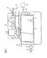
- Figure 1 shows an apparatus 10 for producing a three-dimensional work piece.
- the apparatus 10 comprises a process chamber 12.
- a powder application device 14, which is disposed in the process chamber 12, serves to apply a raw material powder onto a carrier 16.
- the carrier 16 is designed to be displaceable in vertical direction so that, with increasing construction height of a work piece, as it is built up in layers from the raw material powder on the carrier 16, the carrier 16 can be moved downwards in the vertical direction.
- the apparatus 10 further comprises an irradiation unit 18 for selectively irradiating laser radiation onto the raw material powder applied onto the carrier 16.
- the raw material powder applied onto the carrier 18 may be subjected to laser radiation in a site-selective manner in dependence on the desired geometry of the work piece that is to be produced.
- the irradiation unit 18 has a hermetically sealable housing 20.
- a radiation beam 22, in particular a laser beam, provided by a radiation source 24, in particular a laser source which may, for example, comprise a diode pumped Ytterbium fibre laser emitting laser light at a wavelength of approximately 1070 to 1080 nm is directed into the housing 20 via an opening 26.
- the irradiation unit 18 further comprises an optical unit 28 for guiding and processing the radiation beam 22, the optical unit 28 comprising optical elements such as a beam expander 30 for expanding the radiation beam 22 emitted by the radiation source 24, a focusing lens 32 for focusing the radiation beam 22, a scanner unit 34 and an objective lens 35.
- the scanner unit 34 and the object lens 35 may, for example, be designed in the form of a galvanometer scanner and an f-theta object lens. By means of the scanner 34, the position of the focus of the radiation beam 22 both in the direction of the beam path and in a plane perpendicular to the beam path can be changed and adapted.
- the operation of the irradiation unit 18 is controlled by means of a control unit 36.
- the process chamber 12 is sealable against the ambient atmosphere, i.e. against the environment surrounding the process chamber 12.
- the process chamber 12 is connected to a gas supply line 38 via which a gas provided by a gas source 40 may be supplied to the process chamber 12.
- the gas supplied to the process chamber 12 from the gas source 40 may be an inert gas such as, for example, Argon or Nitrogen.
- a discharge line 42 serves to discharge gas containing particulate impurities such as, for example, raw material powder particles or welding smoke particles from the process chamber 12 during irradiating electromagnetic or particle radiation onto the raw material powder applied onto the carrier 16 in order to produce a work piece made of said raw material powder by an additive layer construction method.
- the gas containing particulate impurities is discharged from the process chamber 12 by means of a conveying device 44 such as, for example, a pump.
- a filter 46 disposed in the discharge line 42 upstream of the conveying device 44 serves to filter the particulate impurities from the gas stream discharged from the process chamber 12 After passing the filter 46 the gas stream may be recirculated into the process chamber 12 via the gas supply line 38.
- the apparatus 10 comprises a pyrometric detection device 39 as described in non-published European patent application EP 14 194 387 .
- the optical properties such as, for example, the refractive index and the geometry of the optical elements 30, 32, 34, 35 of the irradiation unit 18 change in dependence on the operating temperature of the irradiation unit 18 which in turn mainly depends on the output power of the radiation beam 22 emitted by the radiation source 24 of the irradiation unit 18.
- These temperature-induced changes in the refractive index of the optical materials used for manufacturing the optical elements 30, 32, 34, 35 as well as temperature induced changes in the geometry of the optical elements 30, 32, 34, 35 lead to a shift of the focus position of the radiation beam 22 emitted by the radiation source 24.
- the focus position of the radiation beam 22, due to the temperature-induced changes of the optical properties of the optical elements 30, 32, 34, 35, with increasing operating temperature of the irradiation unit 18, is progressively shifted along the beam path of the radiation beam 22 and hence in the direction of a z-axis of a coordinate system, wherein the x-axis and the y-axis define a plane formed by the surface of the raw material powder to be irradiated, and wherein the z-axis extends perpendicular to the x- and the y-axis in the direction of the irradiation unit 18.
- the irradiation unit 18 Upon manufacturing the apparatus 10 for producing a three-dimensional work piece, a quality check of the irradiation unit 18 is performed.
- the irradiation unit 18 which is equipped with at least one, but usually all of the optical elements 30, 32, 34, 35 is provided and installed in the apparatus 10.
- the output power of the radiation beam 22 is set to 10% of the maximum output power and a first value of the shift of the focus position which is induced by the temperature-induces changes in the optical properties of the at least one optical element 30, 32, 34, 35 of the irradiation unit 18 is measured. Since more or less no shift of the focus position of the radiation beam 22 occurs at an output power of the radiation beam 22 of 10% of the maximum output power, the value for the shift of the focus position measured at an output power of the radiation beam 22 of 10% of the maximum output power is taken a reference value.
- values of the shift of the focus position which is induced by the temperature-induces changes in the optical properties of the at least one optical element 30, 32, 34, 35 of the irradiation unit 18 is measured at an output power of the radiation beam 22 of 25% of the maximum output power and 100% of the maximum output power.
- the at least one optical element 30, 32, 34, 35 of the irradiation unit 18 is selected for final installation in the apparatus 10 only in case the temperature dependent shift of the focus position of the radiation beam 22 emitted by the radiation source 24 of the irradiation unit 18 is below a threshold value.
- the at least one optical element 30, 32, 34, 35 meets the required quality standards only in case the focus position shift along the z-axis of the above defined coordinate system, which is induced by the operating temperature depended changes in the optical properties of the at least one optical element 30, 32, 34, 35, is below 0.5 of the Raleigh length of the radiation beam 22.
- a calibration measurement is performed.
- the calibration measurement outlined further below is performed according to a caustic measurement method with the aid of a caustic measurement device 48 which is detachably provided to the apparatus 10 and therefore may be removed from the apparatus 10 after completion of the calibration process.
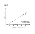
- the shift of the focus position which is induced by the temperature-induces changes in the optical properties of the optical elements 30, 32, 34, 35 of the irradiation unit 18, is measured at selected output power values of the radiation beam 22 in order to obtain the measured values indicated in the diagram of Fig. 2 .
- the measured values indicate the shift of the focus position of the radiation beam 22 in the direction of the z-axis of the above defined coordinate system which is caused by the operating temperature-induced changes in the optical properties of the optical elements 30, 32, 34, 35.
- Fig. 2 more or less no shift of the focus position of the radiation beam 22 occurs at an output power of the radiation beam 22 of 10% of the maximum output power. With increasing output power of the radiation beam 22, the shift progressively increases.
- a correction function indicating the shift of the focus position in one spatial direction, i.e. in the direction of the z-axis of the above defined coordinate system, in dependence on the output power of the radiation beam 22 is determined.
- the correction function is the result of a linear regression analysis performed on the measured values. It is, however, also conceivable to use a higher order function in the regression analysis for obtaining the correction function.
- the correction function is input into the control unit 36.
- the correction function may be stored in a memory of the control unit 36.
- the control unit 36 controls the operation of the irradiation unit 18 in dependence on an operating temperature dependent change of the optical properties of the optical elements 30, 32, 34, 35 of the irradiation unit 18. Specifically, the control unit 36 controls the operation of the irradiation unit 18 so as to compensate for the operating temperature dependent change of the optical properties of the optical element 30, 32, 34, 35. With the aid of the correction function, the control unit 36 controls the operation of the irradiation unit 18 in dependence on the operating temperature dependent shift of the focus position of the radiation beam 22 so as to compensate for said operating temperature dependent shift of the focus position.
- the calibration measurement described above may be performed only once, for example, upon manufacturing the apparatus 10. It is, however, also possible to perform calibration measurements at regular time intervals, for example as a part of the maintenance work performed on the apparatus 10 for producing a three-dimensional work piece.
- the pyrometric detection device 39 may be used for performing the regular calibration measurements.
Landscapes
- Engineering & Computer Science (AREA)
- Chemical & Material Sciences (AREA)
- Materials Engineering (AREA)
- Physics & Mathematics (AREA)
- Manufacturing & Machinery (AREA)
- Optics & Photonics (AREA)
- Plasma & Fusion (AREA)
- Mechanical Engineering (AREA)
- Toxicology (AREA)
- Health & Medical Sciences (AREA)
- General Health & Medical Sciences (AREA)
- Automation & Control Theory (AREA)
- Analytical Chemistry (AREA)
- Ceramic Engineering (AREA)
- General Physics & Mathematics (AREA)
- Powder Metallurgy (AREA)
- Laser Beam Processing (AREA)
- Mechanical Optical Scanning Systems (AREA)
Abstract
Description
- The present invention relates to a method and an apparatus for producing a three-dimensional work piece by irradiating layers of a raw material powder with electromagnetic or particle radiation. Further, the invention relates to a method for manufacturing an apparatus for producing a three-dimensional work piece by irradiating layers of a raw material powder with electromagnetic or particle radiation.
- Powder bed fusion is an additive layering process by which pulverulent, in particular metallic and/or ceramic raw materials can be processed to three-dimensional work pieces of complex shapes. To that end, a raw material powder layer is applied onto a carrier and subjected to laser radiation in a site selective manner in dependence on the desired geometry of the work piece that is to be produced. The laser radiation penetrating into the powder layer causes heating and consequently melting or sintering of the raw material powder particles. Further raw material powder layers are then applied successively to the layer on the carrier that has already been subjected to laser treatment, until the work piece has the desired shape and size. Powder bed fusion may be employed for the production of prototypes, tools, replacement parts, high value components or medical prostheses, such as, for example, dental or orthopaedic prostheses, on the basis of CAD data.
- An apparatus for producing moulded bodies from pulverulent raw materials by a powder bed fusion process is described, for example, in
EP 1 793 979 B1 . The prior art apparatus comprises a process chamber which accommodates a plurality of carriers for the shaped bodies to be manufactured. A powder layer preparation system comprises a powder reservoir holder that can be moved to and fro across the carriers in order to apply a raw material powder to be irradiated with a laser beam onto the carriers. The process chamber is connected to a protective gas circuit comprising a supply line via which a protective gas may be supplied to the process chamber in order to establish a protective gas atmosphere within the process chamber. - An irradiation unit which may, for example, be employed in an apparatus for producing three-dimensional work pieces by irradiating pulverulent raw materials is described in
EP 2 335 848 B1 . The irradiation unit comprises a laser source and an optical unit. The optical unit which is supplied with a laser beam emitted by the laser source comprises a beam expander and a scanner unit. Within the scanner unit, diffractive optical elements which may be folded into the beam path in order to split the laser beam into a plurality of laser sub-beams are arranged in front of a deflection mirror for deflecting the laser sub-beams. The laser beam or the laser sub-beams emitted by the scanner unit are supplied to an objective lens which is designed in the form of an f-theta lens. - The invention is directed at the object of providing a method and an apparatus, which allow the generation of a high-quality three-dimensional work piece by irradiating layers of a raw material powder with electromagnetic or particle radiation. Further, the invention is directed at the object of providing a method for manufacturing an apparatus of this kind.
- These objects are addressed by a method for producing a three-dimensional work piece as defined in claim 1, an apparatus for producing a three-dimensional work piece as defined in claim 8, and a method for manufacturing an apparatus for producing a three-dimensional work piece as defined in claim 15.
- In a method for producing a three-dimensional work piece, a raw material powder is applied onto a carrier. The carrier may be disposed in a process chamber which may be sealable against the ambient atmosphere, in order to be able to maintain a controlled atmosphere, in particular an inert atmosphere within the process chamber. The carrier may be a rigidly fixed carrier. Preferably, however, the carrier is designed to be displaceable in vertical direction so that, with increasing construction height of a work piece, as it is built up in layers from the raw material powder, the carrier can be moved downwards in the vertical direction. The raw material powder preferably is a metallic powder, in particular a metal alloy powder, but may also be a ceramic powder or a powder containing different materials. The powder may have any suitable particle size or particle size distribution. It is, however, preferable to process powders of particle sizes < 100 µm. The raw material powder may be applied onto the carrier by means of a suitable powder application device
- The raw material powder applied onto the carrier, by means of an irradiation unit, is selectively irradiated with electromagnetic or particle radiation in order to produce the work piece from the raw material powder on the carrier by a generative layer construction method. The irradiation unit comprises a radiation source and a plurality of optical elements. The irradiation unit may comprise only one radiation source. It is, however, also conceivable that the irradiation unit comprises a plurality of radiation sources. In case the irradiation unit comprises a plurality of radiation sources, a separate optical unit comprising a plurality of optical elements may be associated with each radiation source. The at least one radiation source may be a laser source, for example a diode pumped Ytterbium fibre laser. Further, the plurality of optical elements may, for example, include a beam expander for expanding a radiation beam emitted by the radiation source, a scanner and an object lens. Alternatively, the plurality of optical elements may comprise a beam expander including a focusing optic and a scanner unit. By means of the scanner unit, the position of a focus of the radiation beam both in the direction of the beam path and in a plane perpendicular to the beam path can be changed and adapted. The scanner unit may be designed in the form of a galvanometer scanner and the object lens may be an f-theta object lens.
- In the method for producing a three-dimensional work piece, operation of the irradiation unit is controlled in dependence on an operating temperature dependent change of at least one optical property of at least one optical element of the irradiation unit. It has been found that optical properties such as, for example, the refractive index of an optical fiber, a lens or another optical element of the irradiation unit or the geometry, in particular the curvature radius of a lens forming an optical element of the irradiation unit change in dependence on the operating temperature of the irradiation unit. The operating temperature of the irradiation unit in turn mainly depends on the output power of a radiation beam emitted by the radiation source of the irradiation unit. In the method for producing a three-dimensional work piece, the operating temperature dependent change of at least one optical property of at least one optical element of the irradiation unit is considered upon controlling the operation of the irradiation unit. As a result, operation of the irradiation unit can be controlled more accurately and a three-dimensional work piece which meets particularly high quality standards can be obtained.
- Basically, the method for producing a three-dimensional work piece which involves a control of the operation of the irradiation unit in dependence on an operating temperature dependent change of at least one optical property of at least one optical element of the irradiation unit can be already advantageously employed when the three-dimensional work piece is produced with the aid of an irradiation unit which employs a single radiation source emitting a single radiation beam. However, especially in case a three-dimensional work piece should be produced by simultaneously irradiating electromagnetic or particle radiation provided by a plurality of irradiation units onto the raw material powder applied onto the carried, control of the various irradiation units in dependence on an operating temperature dependent change of at least one optical property of at least one optical element of the irradiation units allows the irradiation units to be synchronized as regards the operating temperature dependent change of at least one optical property of at least one optical element of each irradiation unit. In other words, the irradiation units may be controlled so as to level or balance different operating temperature dependent changes of the optical properties of the optical elements employed in the irradiation units. Thus, a high quality work piece can be produced even in case the optical elements of the various irradiation units are subject to different operating temperature dependent changes of at least one optical property of the optical elements.
- Preferably, operation of the irradiation unit is controlled so as to compensate for the operating temperature dependent change of the at least one optical property of the at least one optical element of the irradiation unit. This allows maintaining the quality of the three-dimensional work piece to be generated unaffected by the change of the at least one optical property of the at least one optical element of the irradiation unit when the output power of the radiation beam emitted by the radiation source of the irradiation unit and hence the operating temperature of the irradiation unit is changed, for example, for producing different regions of the work piece to be generated.
- In a particular preferred embodiment of the method for producing a three-dimensional work piece, operation of the irradiation unit is controlled in dependence on an operating temperature dependent shift of a focus position of an radiation beam emitted by the radiation source of the irradiation unit in at least one spatial direction. Typically, temperature-induced changes in the refractive index of the optical materials used for manufacturing the optical elements of the irradiation unit as well as temperature induced changes in the geometry, such as, for example, a curvature radius, of the optical elements of the irradiation unit lead to a shift of the focus position of the radiation beam emitted by the radiation source of the irradiation unit. Specifically, it has been found that the focus position of the radiation beam, due to the temperature-induced changes of the optical properties of the optical elements of the irradiation unit, with increasing operating temperature of the irradiation unit is progressively shifted along the beam path of the radiation beam and hence in the direction of a z-axis of a coordinate system, wherein the x-axis and the y-axis define a plane formed by the surface of the raw material powder to be irradiated, and wherein the z-axis extends perpendicular to the x- and the y-axis in the direction of the irradiation unit.
- Operation of the irradiation unit therefore preferably is controlled in dependence on an operating temperature dependent shift of the focus position of the radiation beam emitted by the radiation source of the irradiation unit in the direction of the z-axis of the above defined coordinate system. Considering the operating temperature dependent shift of the focus position of the radiation beam emitted by the radiation source in at least one spatial direction and preferably in the direction of the z-axis of the above defined coordinate system upon controlling the operation of the irradiation unit is a relatively easily to establish, but still very effective way of putting into practice a control of the operation of the irradiation unit in dependence on an operating temperature dependent change of at least one optical property of at least one optical element of the irradiation unit.
- In a preferred embodiment of the method for producing a three-dimensional work piece, operation of the irradiation unit is controlled so as to compensate for the operating temperature dependent shift of a focus position of the radiation beam emitted by the radiation source of the irradiation unit in at least one spatial direction. For example, the irradiation unit may be controlled in such a manner that the focus position of the radiation beam in at least one spatial direction is adjusted in dependence on the operating temperature of the irradiation unit so as to maintain the focus position of the radiation beam constant in at least one spatial direction even in case the operating temperature of the irradiation unit changes. Preferably, operation of the irradiation unit is controlled so as to compensate for the operating temperature dependent shift of a focus position of the radiation beam emitted by the radiation source of the irradiation unit in the direction of the z-axis of the above defined coordinate system.
- In a particular preferred embodiment of the method for producing a three-dimensional work piece, operation of the irradiation unit is controlled in dependence on a correction function indicating a shift of the focus position of the radiation beam emitted by the radiation source of the irradiation unit in one spatial direction in dependence on an output power of the radiation beam emitted by the radiation source of the irradiation unit. The spatial direction preferably is the direction of the z-axis of the above defined coordinate system, i.e. the direction perpendicular to the plane defined by the surface of the raw material powder to be irradiated. The use of a correction function allows the operation of the irradiation unit to be controlled in dependence on the operating temperature-dependent change of at least one optical property of at least one optical element of the irradiation unit over the entire range of possible output power values of the radiation beam.
- Preferably, the correction function is the result of a regression analysis performed on data obtained via a calibration measurement of the shift of the focus position of the radiation beam emitted by the radiation source of the irradiation unit in one spatial direction, preferably in the direction of the z-axis of the above defined coordinate system, in dependence on the output power of the radiation beam emitted by the radiation source of the irradiation unit. In one embodiment, the correction function may be a linear function obtained as a result of a linear regression analysis performed on the calibration measurement data. If desired or necessary, it is, however, also conceivable to use a higher order function in the regression analysis for obtaining the correction function. The calibration measurement preferably is performed prior to starting the production of a three-dimensional work piece, wherein it is conceivable to perform the calibration measurement only once, for example, upon manufacturing an apparatus for producing a three-dimensional work piece. As an alternative, it is, however, also possible to perform calibration measurements at selected time intervals, for example as a part of the maintenance work performed on the apparatus for producing a three-dimensional work piece. Regular calibration measurements allow a compensation of changes in the temperature dependence of at least one optical property of at least one optical element of the irradiation unit over time.
- The calibration measurement may be performed according to a caustic measurement method. A caustic measurement method allows the operating temperature-dependent shift of the focus position of the radiation beam in at least one spatial direction and in particular in the direction of the z-axis of the above defined coordinate system to be determined with a high reliability and a high accuracy. For example, the shift of the focus position of the radiation beam may be determined at an output power of the radiation beam of 10% of the maximum output power, 25% of the maximum output power and 100% of the maximum output power. A regression analysis may then be performed on said data so as to obtain a linear or higher order correction function. The use of a caustic measurement method for performing a calibration measurement, however, requires a caustic measurement device which typically is not part of the scope of delivery of an apparatus for producing three-dimensional work pieces. A caustic measurement method thus is particularly advantageous for performing a presale calibration measurement upon manufacturing the apparatus for producing a three-dimensional work piece.
- Alternatively, the calibration measurement may also be performed according to a pyrometric measurement method. Specifically, a pyrometric detection device as described in non-published European
patent application EP 14 194 387 - An apparatus for producing a three-dimensional work piece comprises a raw material powder application device adapted to apply a raw material powder onto a carrier. An irradiation unit is adapted to selectively irradiate electromagnetic or particle radiation onto the raw material powder applied onto the carrier in order to produce the work piece from said raw material powder on the carrier by a generative layer construction method. The irradiation unit comprises a radiation source and a plurality of optical elements. A control unit is adapted to control operation of the irradiation unit in dependence on an operating temperature dependent change of at least one optical property of at least one optical element on the irradiation unit.
- The control unit may be adapted to control operation of the irradiation unit so as to compensate for the operating temperature dependent change of the at least one optical property of the at least one optical element of the irradiation unit.
- Preferably, the control unit is adapted to control operation of the irradiation unit in dependence on an operating temperature-dependent shift of a focus position of an radiation beam emitted by the radiation source of the irradiation unit in at least one spatial direction.
- Specifically, the control unit may be adapted to control operation of the irradiation unit so as to compensate for the operating temperature-dependent shift of the focus position of the radiation beam emitted by the radiation source of the irradiation unit in at least one spatial direction.
- In a preferred embodiment of the apparatus, the control unit is adapted to control operation of the irradiation unit in dependence on a correction function indicating a shift of the focus position of the radiation beam emitted by the radiation source of the irradiation unit in one spatial direction in dependence on an output power of the radiation beam emitted by the radiation source of the irradiation unit.
- The correction function may be the result of a regression analysis performed on data obtained via a calibration measurement of the shift of the focus position of the radiation beam emitted by the radiation source of the irradiation unit in one spatial direction in dependence on the output power of the radiation beam emitted by the radiation source of the irradiation unit.
- The apparatus may further comprise a caustic measurement device adapted to perform the calibration measurement according to a caustic measurement method. The caustic measurement device may be detachably connected to the apparatus which allows the caustic measurement device to be removed from the apparatus after performing the calibration measurement. Alternatively or additionally thereto, the apparatus may comprise a pyrometric detection device adapted to perform the calibration measurement according to a pyrometric measurement method.
- In a method for manufacturing an apparatus for producing a three-dimensional work piece, an irradiation unit is provided which is adapted to selectively irradiate electromagnetic or particle radiation onto a raw material powder applied onto a carrier in order to produce the work piece from said raw material powder on the carrier by a generative layer construction method. The irradiation unit comprises a radiation source and at least one optical element. An operating temperature dependent shift of a focus position of a radiation beam emitted by the radiation source of the irradiation unit in at least one spatial direction is determined. Preferably, an operating temperature dependent shift of the focus position of the radiation beam emitted by the radiation source in the direction of a z-axis of a coordinate system, wherein the x-axis and the y-axis define a plane formed by the surface of the raw material powder to be irradiated, and wherein the z-axis extends perpendicular to the x- and the y-axis in the direction of the irradiation unit is determined. The at least one optical element of the irradiation unit is selected for final installation in the apparatus in case the temperature dependent shift of the focus position of the radiation beam emitted by the radiation source of the irradiation unit is below a threshold value.
- For example, the shift of the focus position of the radiation beam in at least one spatial direction, in particular in the direction of the z-axis of the above defined coordinate system, may be determined for selected output power values of the radiation beam emitted by the radiation source of the irradiation unit. Specifically, the shift of the focus position of the radiation beam may be determined at an output power of the radiation beam of 10% of the maximum output power, 25% of the maximum output power and 100% of the maximum output power. At an output power of 10% of the maximum output power, more or less no shift of the focus positon of the radiation beam occurs. The focus position shift measured at an output power of the radiation beam of 10% of the maximum output power thus may be used as a reference value for the following measurements at for example 25% and 100% of the maximum output power of the radiation beam. The at least one optical element irradiation unit may, for example, be selected for final installation in the apparatus only in case the focus position shift along the z-axis of the above defined coordinate system is below 0.5 of the Raleigh length of the radiation beam. If desired, plural optical elements intended for being employed in the irradiation unit and for finally being installed in the apparatus may be tested and selected in this manner.
- Preferred embodiments of the invention now are described in greater detail with reference to the appended schematic drawings wherein
- Fig. 1
- shows an apparatus for producing three-dimensional work pieces by selectively irradiating electromagnetic or particle radiation onto a raw material powder and
- Fig. 2
- shows a diagram indicating a shift of a focus position of a radiation beam emitted by a radiation source of an irradiation unit employed in the apparatus of
Fig. 1 which is caused by a change of the optical properties of the optical elements of the irradiation unit in dependence on the output power of the radiation beam. -
Figure 1 shows anapparatus 10 for producing a three-dimensional work piece. Theapparatus 10 comprises aprocess chamber 12. Apowder application device 14, which is disposed in theprocess chamber 12, serves to apply a raw material powder onto acarrier 16. Thecarrier 16 is designed to be displaceable in vertical direction so that, with increasing construction height of a work piece, as it is built up in layers from the raw material powder on thecarrier 16, thecarrier 16 can be moved downwards in the vertical direction. - The
apparatus 10 further comprises anirradiation unit 18 for selectively irradiating laser radiation onto the raw material powder applied onto thecarrier 16. By means of theirradiation unit 20, the raw material powder applied onto thecarrier 18 may be subjected to laser radiation in a site-selective manner in dependence on the desired geometry of the work piece that is to be produced. Theirradiation unit 18 has a hermeticallysealable housing 20. Aradiation beam 22, in particular a laser beam, provided by aradiation source 24, in particular a laser source which may, for example, comprise a diode pumped Ytterbium fibre laser emitting laser light at a wavelength of approximately 1070 to 1080 nm is directed into thehousing 20 via anopening 26. - The
irradiation unit 18 further comprises anoptical unit 28 for guiding and processing theradiation beam 22, theoptical unit 28 comprising optical elements such as a beam expander 30 for expanding theradiation beam 22 emitted by theradiation source 24, a focusinglens 32 for focusing theradiation beam 22, ascanner unit 34 and an objective lens 35. Thescanner unit 34 and the object lens 35 may, for example, be designed in the form of a galvanometer scanner and an f-theta object lens. By means of thescanner 34, the position of the focus of theradiation beam 22 both in the direction of the beam path and in a plane perpendicular to the beam path can be changed and adapted. The operation of theirradiation unit 18 is controlled by means of acontrol unit 36. - The
process chamber 12 is sealable against the ambient atmosphere, i.e. against the environment surrounding theprocess chamber 12. Theprocess chamber 12 is connected to agas supply line 38 via which a gas provided by agas source 40 may be supplied to theprocess chamber 12. The gas supplied to theprocess chamber 12 from thegas source 40 may be an inert gas such as, for example, Argon or Nitrogen. Adischarge line 42 serves to discharge gas containing particulate impurities such as, for example, raw material powder particles or welding smoke particles from theprocess chamber 12 during irradiating electromagnetic or particle radiation onto the raw material powder applied onto thecarrier 16 in order to produce a work piece made of said raw material powder by an additive layer construction method. The gas containing particulate impurities is discharged from theprocess chamber 12 by means of a conveyingdevice 44 such as, for example, a pump. Afilter 46 disposed in thedischarge line 42 upstream of the conveyingdevice 44 serves to filter the particulate impurities from the gas stream discharged from theprocess chamber 12 After passing thefilter 46 the gas stream may be recirculated into theprocess chamber 12 via thegas supply line 38. Finally, theapparatus 10 comprises apyrometric detection device 39 as described in non-published Europeanpatent application EP 14 194 387 - The optical properties such as, for example, the refractive index and the geometry of the
optical elements irradiation unit 18 change in dependence on the operating temperature of theirradiation unit 18 which in turn mainly depends on the output power of theradiation beam 22 emitted by theradiation source 24 of theirradiation unit 18. These temperature-induced changes in the refractive index of the optical materials used for manufacturing theoptical elements optical elements radiation beam 22 emitted by theradiation source 24. Specifically, the focus position of theradiation beam 22, due to the temperature-induced changes of the optical properties of theoptical elements irradiation unit 18, is progressively shifted along the beam path of theradiation beam 22 and hence in the direction of a z-axis of a coordinate system, wherein the x-axis and the y-axis define a plane formed by the surface of the raw material powder to be irradiated, and wherein the z-axis extends perpendicular to the x- and the y-axis in the direction of theirradiation unit 18. - Upon manufacturing the
apparatus 10 for producing a three-dimensional work piece, a quality check of theirradiation unit 18 is performed. For this purpose, theirradiation unit 18 which is equipped with at least one, but usually all of theoptical elements apparatus 10. Thereafter, the operating temperature dependent shift of the focus position of theradiation beam 22 emitted by theradiation source 24 of theirradiation unit 18 in at least one spatial direction, in particular in the direction of the z-axis of the coordinate system, wherein the x-axis and the y-axis define the plane formed by the surface of the raw material powder to be irradiated, and wherein the z-axis extends perpendicular to the x- and the y-axis in the direction of theirradiation unit 18 is determined. Specifically, in a first step, the output power of theradiation beam 22 is set to 10% of the maximum output power and a first value of the shift of the focus position which is induced by the temperature-induces changes in the optical properties of the at least oneoptical element irradiation unit 18 is measured. Since more or less no shift of the focus position of theradiation beam 22 occurs at an output power of theradiation beam 22 of 10% of the maximum output power, the value for the shift of the focus position measured at an output power of theradiation beam 22 of 10% of the maximum output power is taken a reference value. - Thereafter, values of the shift of the focus position which is induced by the temperature-induces changes in the optical properties of the at least one
optical element irradiation unit 18 is measured at an output power of theradiation beam 22 of 25% of the maximum output power and 100% of the maximum output power. The at least oneoptical element irradiation unit 18 is selected for final installation in theapparatus 10 only in case the temperature dependent shift of the focus position of theradiation beam 22 emitted by theradiation source 24 of theirradiation unit 18 is below a threshold value. In particular, it is determined that the at least oneoptical element optical element radiation beam 22. - In case it is determined that the at least one
optical element apparatus 10, a calibration measurement is performed. Like the above described quality check measurements, also the calibration measurement outlined further below is performed according to a caustic measurement method with the aid of acaustic measurement device 48 which is detachably provided to theapparatus 10 and therefore may be removed from theapparatus 10 after completion of the calibration process. In the calibration measurement, the shift of the focus position, which is induced by the temperature-induces changes in the optical properties of theoptical elements irradiation unit 18, is measured at selected output power values of theradiation beam 22 in order to obtain the measured values indicated in the diagram ofFig. 2 . Specifically, the measured values indicate the shift of the focus position of theradiation beam 22 in the direction of the z-axis of the above defined coordinate system which is caused by the operating temperature-induced changes in the optical properties of theoptical elements Fig. 2 , more or less no shift of the focus position of theradiation beam 22 occurs at an output power of theradiation beam 22 of 10% of the maximum output power. With increasing output power of theradiation beam 22, the shift progressively increases. - Based on the measured values of the shift of the focus position of the
radiation beam 22, a correction function indicating the shift of the focus position in one spatial direction, i.e. in the direction of the z-axis of the above defined coordinate system, in dependence on the output power of theradiation beam 22 is determined. In the diagram ofFig. 2 , the correction function is the result of a linear regression analysis performed on the measured values. It is, however, also conceivable to use a higher order function in the regression analysis for obtaining the correction function. The correction function is input into thecontrol unit 36. For example, the correction function may be stored in a memory of thecontrol unit 36. - During operation of the
apparatus 10 so as to produce a three-dimensional work piece, thecontrol unit 36 controls the operation of theirradiation unit 18 in dependence on an operating temperature dependent change of the optical properties of theoptical elements irradiation unit 18. Specifically, thecontrol unit 36 controls the operation of theirradiation unit 18 so as to compensate for the operating temperature dependent change of the optical properties of theoptical element control unit 36 controls the operation of theirradiation unit 18 in dependence on the operating temperature dependent shift of the focus position of theradiation beam 22 so as to compensate for said operating temperature dependent shift of the focus position. This allows maintaining the quality of the three-dimensional work piece to be generated unaffected by the operating temperature induced changes of the optical properties of theoptical elements radiation beam 22 and hence the operating temperature of theirradiation unit 18 is changed, for example, for producing different regions of the work piece to be generated. - The calibration measurement described above may be performed only once, for example, upon manufacturing the
apparatus 10. It is, however, also possible to perform calibration measurements at regular time intervals, for example as a part of the maintenance work performed on theapparatus 10 for producing a three-dimensional work piece. Thepyrometric detection device 39 may be used for performing the regular calibration measurements.
Claims (15)
- A method for producing a three-dimensional work piece, the method comprising the steps of:- applying a raw material powder onto a carrier (16),- selectively irradiating electromagnetic or particle radiation onto the raw material powder applied onto the carrier (16) by means of an irradiation unit (18) in order to produce the work piece from said raw material powder on the carrier (16) by a generative layer construction method, the irradiation unit (18) comprising a radiation source (24) and a plurality of optical elements (30, 32, 34, 35),
wherein operation of the irradiation unit (18) is controlled in dependence on an operating temperature dependent change of at least one optical property of at least one optical element (30, 32, 34, 35) of the irradiation unit (18). - The method according to claim 1,
wherein operation of the irradiation unit (18) is controlled so as to compensate for the operating temperature dependent change of the at least one optical property of the at least one optical element (30, 32, 34, 35) of the irradiation unit (18). - The method according to claim 1 or 2,
wherein operation of the irradiation unit (18) is controlled in dependence on an operating temperature dependent shift of a focus position of an radiation beam (22) emitted by the radiation source (24) of the irradiation unit (18) in at least one spatial direction. - The method according to claim 3,
wherein operation of the irradiation unit (18) is controlled so as to compensate for the operating temperature dependent shift of the focus position of the radiation beam (22) emitted by the radiation source (24) of the irradiation unit (18) in at least one spatial direction. - The method according to any one of claims 1 to 4,
wherein operation of the irradiation unit (18) is controlled in dependence on a correction function indicating a shift of the focus position of the radiation beam (22) emitted by the radiation source (24) of the irradiation unit (18) in one spatial direction in dependence on an output power of the radiation beam (22) emitted by the radiation source (24) of the irradiation unit (18). - The method according to claim 5,
wherein the correction function is the result of a regression analysis performed on data obtained via a calibration measurement of the shift of the focus position of the radiation beam (22) emitted by the radiation source (24) of the irradiation unit (18) in one spatial direction in dependence on the output power of the radiation beam (22) emitted by the radiation source (24) of the irradiation unit (18). - The method according to claim 6,
wherein the calibration measurement is performed according to a caustic measurement method and/or a pyrometric measurement method. - An apparatus (10) for producing a three-dimensional work piece, the apparatus (10) comprising:- a raw material powder application device (14) adapted to apply a raw material powder onto a carrier (16),- an irradiation unit (18) adapted to selectively irradiate electromagnetic or particle radiation onto the raw material powder applied onto the carrier (16) in order to produce the work piece from said raw material powder on the carrier (16) by a generative layer construction method, the irradiation unit (18) comprising a radiation source (24) and a plurality of optical elements (30, 32, 34, 35), and a control unit (36) adapted to control operation of the irradiation unit (18) in dependence on an operating temperature dependent change of at least one optical property of at least one optical element (30, 32, 34, 35) of the irradiation unit (18).
- The apparatus according to claim 1,
wherein the control unit (36) is adapted to control operation of the irradiation unit (18) so as to compensate for the operating temperature dependent change of the at least one optical property of the at least one optical element (30, 32, 34, 35) of the irradiation unit (18). - The apparatus according to claim 8 or 9,
wherein the control unit (36) is adapted to control operation of the irradiation unit (18) in dependence on an operating temperature dependent shift of a focus position of an radiation beam (22) emitted by the radiation source (24) of the irradiation unit (18) in at least one spatial direction. - The apparatus according to claim 10,
wherein the control unit (36) is adapted to control operation of the irradiation unit (18) so as to compensate for the operating temperature dependent shift of the focus position of the radiation beam (22) emitted by the radiation source (24) of the irradiation unit (18) in at least one spatial direction. - The apparatus according to any one of claims 8 to 11,
wherein the control unit (36) is adapted to control operation of the irradiation unit (18) in dependence on a correction function indicating a shift of the focus position of the radiation beam (22) emitted by the radiation source (24) of the irradiation unit (18) in one spatial direction in dependence on an output power of the radiation beam (22) emitted by the radiation source (24) of the irradiation unit (18). - The apparatus according to claim 12,
wherein the correction function is the result of a regression analysis performed on data obtained via a calibration measurement of the shift of the focus position of the radiation beam (22) emitted by the radiation source (24) of the irradiation unit (18) in one spatial direction in dependence on the output power of the radiation beam (22) emitted by the radiation source (24) of the irradiation unit (18). - The apparatus according to claim 13,
further comprising a caustic measurement device adapted to perform the calibration measurement according to a caustic measurement method and/or a pyrometric detection device (39) adapted to perform the calibration measurement according to a pyrometric measurement method. - A method for manufacturing an apparatus (10) for producing a three-dimensional work piece, the method comprising:- providing an irradiation unit (18) adapted to selectively irradiate electromagnetic or particle radiation onto a raw material powder applied onto a carrier (16) in order to produce the work piece from said raw material powder on the carrier (16) by a generative layer construction method, the irradiation unit (18) comprising a radiation source (24) and at least one optical element (30, 32, 34, 35),- determining an operating temperature dependent shift of a focus position of an radiation beam (22) emitted by the radiation source (24) of the irradiation unit (18), and- selecting the optical element (30, 32, 34, 35) of the irradiation unit (18) for final installation in the apparatus (10) in case the temperature dependent shift of the focus position of the radiation beam (22) emitted by the radiation source (24) of the irradiation unit (18) in at least one spatial direction is below a threshold value.
Priority Applications (5)
| Application Number | Priority Date | Filing Date | Title |
|---|---|---|---|
| EP15158611.2A EP3067132A1 (en) | 2015-03-11 | 2015-03-11 | Method and apparatus for producing a three-dimensional work piece with thermal focus shift compensation of the laser |
| JP2016040922A JP6214697B2 (en) | 2015-03-11 | 2016-03-03 | Method and apparatus for manufacturing a three-dimensional workpiece by correcting defocus due to heat |
| RU2016107648A RU2639110C2 (en) | 2015-03-11 | 2016-03-03 | Method of manufacture of three-dimensional product, device for manufacture of three-dimensional product and method of manufacture of such device |
| CN201610132941.XA CN105965015B (en) | 2015-03-11 | 2016-03-09 | The method and apparatus for compensating production 3 D workpiece using hot focal shift |
| US15/067,808 US20160263704A1 (en) | 2015-03-11 | 2016-03-11 | Method and apparatus for producing a three-dimensional workpiece with thermal focus shift compensation |
Applications Claiming Priority (1)
| Application Number | Priority Date | Filing Date | Title |
|---|---|---|---|
| EP15158611.2A EP3067132A1 (en) | 2015-03-11 | 2015-03-11 | Method and apparatus for producing a three-dimensional work piece with thermal focus shift compensation of the laser |
Publications (1)
| Publication Number | Publication Date |
|---|---|
| EP3067132A1 true EP3067132A1 (en) | 2016-09-14 |
Family
ID=52684033
Family Applications (1)
| Application Number | Title | Priority Date | Filing Date |
|---|---|---|---|
| EP15158611.2A Pending EP3067132A1 (en) | 2015-03-11 | 2015-03-11 | Method and apparatus for producing a three-dimensional work piece with thermal focus shift compensation of the laser |
Country Status (5)
| Country | Link |
|---|---|
| US (1) | US20160263704A1 (en) |
| EP (1) | EP3067132A1 (en) |
| JP (1) | JP6214697B2 (en) |
| CN (1) | CN105965015B (en) |
| RU (1) | RU2639110C2 (en) |
Cited By (7)
| Publication number | Priority date | Publication date | Assignee | Title |
|---|---|---|---|---|
| EP3243583A1 (en) * | 2016-05-13 | 2017-11-15 | SLM Solutions Group AG | Apparatus and method for associating a position in a construction data set with a position in a building section of the apparatus |
| EP3321005A1 (en) * | 2016-11-14 | 2018-05-16 | SLM Solutions Group AG | Apparatus for producing a three-dimensional work piece with process temperature control |
| EP3495143A1 (en) * | 2017-12-08 | 2019-06-12 | CL Schutzrechtsverwaltungs GmbH | Apparatus for additively manufacturing three-dimensional objects |
| WO2020003142A1 (en) * | 2018-06-27 | 2020-01-02 | Csir | Thermo optical control of focus position of an energy beam in an additive manufacturing apparatus |
| EP3626368A1 (en) * | 2018-09-19 | 2020-03-25 | Concept Laser GmbH | Support frame structure for supporting at least one functional component of an additive manufacturing apparatus |
| WO2020244993A1 (en) * | 2019-06-06 | 2020-12-10 | SLM Solutions Group AG | Apparatus and method |
| WO2022096304A1 (en) | 2020-11-09 | 2022-05-12 | SLM Solutions Group AG | Apparatus for producing a three-dimensional work piece |
Families Citing this family (23)
| Publication number | Priority date | Publication date | Assignee | Title |
|---|---|---|---|---|
| US10618131B2 (en) | 2014-06-05 | 2020-04-14 | Nlight, Inc. | Laser patterning skew correction |
| US11179807B2 (en) | 2015-11-23 | 2021-11-23 | Nlight, Inc. | Fine-scale temporal control for laser material processing |
| CN108367389B (en) | 2015-11-23 | 2020-07-28 | 恩耐公司 | Laser processing method and apparatus |
| KR102498030B1 (en) | 2016-09-29 | 2023-02-08 | 엔라이트 인크. | Tunable Beam Characteristics |
| JP6898449B2 (en) * | 2016-12-29 | 2021-07-07 | スリーディー システムズ インコーポレーテッド | A sensor that simulates the optical properties of resin |
| DE102017205027A1 (en) * | 2017-03-24 | 2018-09-27 | SLM Solutions Group AG | Apparatus and method for producing three-dimensional workpieces |
| EP3607389B1 (en) | 2017-04-04 | 2023-06-07 | Nlight, Inc. | Optical fiducial generation for galvanometric scanner calibration |
| CN106863796B (en) * | 2017-04-12 | 2024-04-05 | 窦鹤鸿 | Laser selective melting device, component and 3D printer |
| WO2018188757A1 (en) * | 2017-04-13 | 2018-10-18 | Siemens Aktiengesellschaft | Method for powder-bed-based additive manufacture of a workpiece, method for producing correction parameters for said first method and computer program product for said second method |
| EP3431289A1 (en) * | 2017-07-21 | 2019-01-23 | CL Schutzrechtsverwaltungs GmbH | Apparatus for additively manufacturing of three-dimensional objects |
| EP3431262A1 (en) * | 2017-07-21 | 2019-01-23 | CL Schutzrechtsverwaltungs GmbH | Plant for additively manufacturing of three-dimensional objects |
| TWI645274B (en) * | 2017-09-12 | 2018-12-21 | 國立臺灣科技大學 | Work piece processing method and processing system thereof |
| US20200276640A1 (en) * | 2017-11-20 | 2020-09-03 | SLM Solutions Group AG | Apparatus and method for producing a three-dimensional work piece |
| CN108248026B (en) * | 2018-01-30 | 2020-06-05 | 深圳升华三维科技有限公司 | Projection type laser heating system and 3D printer |
| US10875094B2 (en) * | 2018-03-29 | 2020-12-29 | Vulcanforms Inc. | Additive manufacturing systems and methods |
| US11426818B2 (en) | 2018-08-10 | 2022-08-30 | The Research Foundation for the State University | Additive manufacturing processes and additively manufactured products |
| DE102018124627B4 (en) * | 2018-10-05 | 2022-02-10 | Precitec Gmbh & Co. Kg | Device for adjusting a focus position of a laser beam in a laser processing system, laser processing system with the same and method for adjusting a focus position of a laser beam in a laser processing system |
| EP3659726B1 (en) * | 2018-11-27 | 2023-01-11 | Additive Industries B.V. | Method for calibrating an apparatus for producing an object by means of additive manufacturing, and apparatus for the method |
| US20220193769A1 (en) * | 2019-03-04 | 2022-06-23 | SLM Solutions Group AG | Control method, control device and production apparatus |
| CN109822243A (en) * | 2019-04-02 | 2019-05-31 | 苏州匠恒智造科技有限公司 | A kind of laser equipment adjusting method based on temperature-compensating |
| CN111619118B (en) * | 2019-12-26 | 2022-03-04 | 南京铖联激光科技有限公司 | Focal plane adjustment closed-loop control system and control method applied to 3D printing equipment |
| JP7096284B2 (en) * | 2020-05-07 | 2022-07-05 | 株式会社ソディック | Manufacturing method for laminated modeling equipment and 3D modeling |
| JP7213220B2 (en) * | 2020-11-17 | 2023-01-26 | 株式会社ソディック | How to calibrate an additive manufacturing machine |
Citations (7)
| Publication number | Priority date | Publication date | Assignee | Title |
|---|---|---|---|---|
| DE102007039878A1 (en) * | 2006-08-18 | 2008-05-08 | Highyag Lasertechnologie Gmbh | Device for focusing a laser beam used during the modification of workpieces comprises a lens group which is mounted so that it can be moved in the axial direction and a further lens group fixed in relation to the other lens group |
| EP1793979B1 (en) | 2004-08-27 | 2009-02-11 | MTT Technologies GmbH | Device for producing molded bodies |
| DE102009044751A1 (en) * | 2008-12-04 | 2010-06-10 | Highyag Lasertechnologie Gmbh | Mirror optics for use in laser working optics of laser radiation formation optical system for laser machining application, has mirrors arranged on collimated laser beam, where opening angle of divergent laser beam is achieved by equation |
| US20130154160A1 (en) * | 2011-12-15 | 2013-06-20 | 3D Systems, Inc. | Stereolithography Systems and Methods Using Internal Laser Modulation |
| EP2335848B1 (en) | 2009-12-04 | 2014-08-20 | SLM Solutions GmbH | Optical irradiation unit for an assembly for producing workpieces by means of irradiating powder layers with laser radiation |
| US20140263209A1 (en) * | 2013-03-15 | 2014-09-18 | Matterfab Corp. | Apparatus and methods for manufacturing |
| EP2878402A1 (en) * | 2013-12-02 | 2015-06-03 | SLM Solutions Group AG | Apparatus and method for producing three-dimensional work pieces with a radiation detection device |
Family Cites Families (10)
| Publication number | Priority date | Publication date | Assignee | Title |
|---|---|---|---|---|
| JPH01122688A (en) * | 1987-11-05 | 1989-05-15 | Sumitomo Electric Ind Ltd | Automatic focal distance adjusting device for lens for laser beam machining |
| US5315111A (en) * | 1992-10-15 | 1994-05-24 | Lasa Industries, Inc. | Method and apparatus for laser beam drift compensation |
| SE524439C2 (en) * | 2002-12-19 | 2004-08-10 | Arcam Ab | Apparatus and method for making a three-dimensional product |
| JP4567984B2 (en) * | 2004-01-30 | 2010-10-27 | 株式会社 日立ディスプレイズ | Flat panel display manufacturing equipment |
| JP4130813B2 (en) * | 2004-05-26 | 2008-08-06 | 松下電工株式会社 | Three-dimensional shaped object manufacturing apparatus and light beam irradiation position and processing position correction method thereof |
| DE102005015870B3 (en) * | 2005-04-06 | 2006-10-26 | Eos Gmbh Electro Optical Systems | Device and method for producing a three-dimensional object |
| DE112007001944B4 (en) * | 2006-08-18 | 2014-05-22 | Highyag Lasertechnologie Gmbh | Method and apparatus for laser material processing |
| EP2094429B9 (en) * | 2006-11-04 | 2017-08-16 | TRUMPF Werkzeugmaschinen GmbH + Co. KG | Method and device for process monitoring during the working of a material |
| JP2009142865A (en) * | 2007-12-14 | 2009-07-02 | Keyence Corp | Laser processing apparatus, laser processing method, and method for making settings for laser processing apparatus |
| DE102010016862B3 (en) * | 2010-05-10 | 2011-09-22 | Precitec Optronik Gmbh | Material processing device with in-situ measurement of the machining distance |
-
2015
- 2015-03-11 EP EP15158611.2A patent/EP3067132A1/en active Pending
-
2016
- 2016-03-03 JP JP2016040922A patent/JP6214697B2/en active Active
- 2016-03-03 RU RU2016107648A patent/RU2639110C2/en active
- 2016-03-09 CN CN201610132941.XA patent/CN105965015B/en active Active
- 2016-03-11 US US15/067,808 patent/US20160263704A1/en not_active Abandoned
Patent Citations (7)
| Publication number | Priority date | Publication date | Assignee | Title |
|---|---|---|---|---|
| EP1793979B1 (en) | 2004-08-27 | 2009-02-11 | MTT Technologies GmbH | Device for producing molded bodies |
| DE102007039878A1 (en) * | 2006-08-18 | 2008-05-08 | Highyag Lasertechnologie Gmbh | Device for focusing a laser beam used during the modification of workpieces comprises a lens group which is mounted so that it can be moved in the axial direction and a further lens group fixed in relation to the other lens group |
| DE102009044751A1 (en) * | 2008-12-04 | 2010-06-10 | Highyag Lasertechnologie Gmbh | Mirror optics for use in laser working optics of laser radiation formation optical system for laser machining application, has mirrors arranged on collimated laser beam, where opening angle of divergent laser beam is achieved by equation |
| EP2335848B1 (en) | 2009-12-04 | 2014-08-20 | SLM Solutions GmbH | Optical irradiation unit for an assembly for producing workpieces by means of irradiating powder layers with laser radiation |
| US20130154160A1 (en) * | 2011-12-15 | 2013-06-20 | 3D Systems, Inc. | Stereolithography Systems and Methods Using Internal Laser Modulation |
| US20140263209A1 (en) * | 2013-03-15 | 2014-09-18 | Matterfab Corp. | Apparatus and methods for manufacturing |
| EP2878402A1 (en) * | 2013-12-02 | 2015-06-03 | SLM Solutions Group AG | Apparatus and method for producing three-dimensional work pieces with a radiation detection device |
Cited By (10)
| Publication number | Priority date | Publication date | Assignee | Title |
|---|---|---|---|---|
| EP3243583A1 (en) * | 2016-05-13 | 2017-11-15 | SLM Solutions Group AG | Apparatus and method for associating a position in a construction data set with a position in a building section of the apparatus |
| US11027494B2 (en) | 2016-05-13 | 2021-06-08 | SLM Solutions Group AG | Device and method for calibrating an irradiation system of an apparatus for producing a three-dimensional work piece |
| EP3321005A1 (en) * | 2016-11-14 | 2018-05-16 | SLM Solutions Group AG | Apparatus for producing a three-dimensional work piece with process temperature control |
| US10710304B2 (en) | 2016-11-14 | 2020-07-14 | SLM Solutions Group AG | Apparatus for producing a three-dimensional work piece with process temperature control |
| EP3495143A1 (en) * | 2017-12-08 | 2019-06-12 | CL Schutzrechtsverwaltungs GmbH | Apparatus for additively manufacturing three-dimensional objects |
| US11904545B2 (en) | 2017-12-08 | 2024-02-20 | Concept Laser Gmbh | Apparatus for additively manufacturing three-dimensional objects |
| WO2020003142A1 (en) * | 2018-06-27 | 2020-01-02 | Csir | Thermo optical control of focus position of an energy beam in an additive manufacturing apparatus |
| EP3626368A1 (en) * | 2018-09-19 | 2020-03-25 | Concept Laser GmbH | Support frame structure for supporting at least one functional component of an additive manufacturing apparatus |
| WO2020244993A1 (en) * | 2019-06-06 | 2020-12-10 | SLM Solutions Group AG | Apparatus and method |
| WO2022096304A1 (en) | 2020-11-09 | 2022-05-12 | SLM Solutions Group AG | Apparatus for producing a three-dimensional work piece |
Also Published As
| Publication number | Publication date |
|---|---|
| RU2639110C2 (en) | 2017-12-19 |
| US20160263704A1 (en) | 2016-09-15 |
| JP2016191144A (en) | 2016-11-10 |
| CN105965015A (en) | 2016-09-28 |
| RU2016107648A (en) | 2017-09-07 |
| CN105965015B (en) | 2018-10-12 |
| JP6214697B2 (en) | 2017-10-18 |
Similar Documents
| Publication | Publication Date | Title |
|---|---|---|
| EP3067132A1 (en) | Method and apparatus for producing a three-dimensional work piece with thermal focus shift compensation of the laser | |
| US10124537B2 (en) | Apparatus and method for producing three-dimensional work pieces with a radiation detection device | |
| US10335854B2 (en) | Method and apparatus for producing three-dimensional work pieces | |
| EP3243583B1 (en) | Apparatus and method for associating a position in a construction data set with a position in a building section of the apparatus | |
| US10682701B2 (en) | Apparatus for producing a three-dimensional work piece with improved gas flow | |
| US10974457B2 (en) | Device and method for calibrating an irradiation system of an apparatus for producing a three-dimensional work piece | |
| EP2961549B1 (en) | Apparatus and method for producing work pieces having a tailored microstructure | |
| US9878497B2 (en) | Method and device for controlling an irradiation system | |
| EP2992986A1 (en) | Apparatus for producing three-dimensional work pieces by additive layer manufacturing method which comprises a drying device | |
| CN108421974B (en) | Apparatus for producing three-dimensional workpieces comprising a heating system | |
| CN110435141B (en) | Device for additive production of three-dimensional objects | |
| CN117794669A (en) | Amplifying offset correction method | |
| CN111201099B (en) | Apparatus and method for manufacturing three-dimensional workpiece | |
| JP2019104230A (en) | Apparatus for additively manufacturing three-dimensional object | |
| CN114514082A (en) | Techniques for analyzing sensor data in powder bed additive manufacturing | |
| Ashton | Investigations into Process Monitoring for Selective Laser Melting |
Legal Events
| Date | Code | Title | Description |
|---|---|---|---|
| PUAI | Public reference made under article 153(3) epc to a published international application that has entered the european phase |
Free format text: ORIGINAL CODE: 0009012 |
|
| 17P | Request for examination filed |
Effective date: 20151201 |
|
| AK | Designated contracting states |
Kind code of ref document: A1 Designated state(s): AL AT BE BG CH CY CZ DE DK EE ES FI FR GB GR HR HU IE IS IT LI LT LU LV MC MK MT NL NO PL PT RO RS SE SI SK SM TR |
|
| AX | Request for extension of the european patent |
Extension state: BA ME |
|
| RAP1 | Party data changed (applicant data changed or rights of an application transferred) |
Owner name: SLM SOLUTIONS GROUP AG |
|
| STAA | Information on the status of an ep patent application or granted ep patent |
Free format text: STATUS: EXAMINATION IS IN PROGRESS |
|
| 17Q | First examination report despatched |
Effective date: 20181129 |
|
| RIN1 | Information on inventor provided before grant (corrected) |
Inventor name: SCHWARZE, DR. DIETER Inventor name: KROL, TONI ADAM Inventor name: WIESNER, ANDREAS |
|
| STAA | Information on the status of an ep patent application or granted ep patent |
Free format text: STATUS: EXAMINATION IS IN PROGRESS |
|
| STAA | Information on the status of an ep patent application or granted ep patent |
Free format text: STATUS: EXAMINATION IS IN PROGRESS |
|
| RAP1 | Party data changed (applicant data changed or rights of an application transferred) |
Owner name: NIKON SLM SOLUTIONS AG |
|
| RIN1 | Information on inventor provided before grant (corrected) |
Inventor name: WIESNER, ANDREAS Inventor name: KROL, TONI ADAM Inventor name: SCHWARZE, DIETER |