EP0398037A2 - Packet network with communication resource allocation and call set up control of higher quality of service - Google Patents
Packet network with communication resource allocation and call set up control of higher quality of service Download PDFInfo
- Publication number
- EP0398037A2 EP0398037A2 EP90107553A EP90107553A EP0398037A2 EP 0398037 A2 EP0398037 A2 EP 0398037A2 EP 90107553 A EP90107553 A EP 90107553A EP 90107553 A EP90107553 A EP 90107553A EP 0398037 A2 EP0398037 A2 EP 0398037A2
- Authority
- EP
- European Patent Office
- Prior art keywords
- calls
- call
- type
- resource
- sub
- Prior art date
- Legal status (The legal status is an assumption and is not a legal conclusion. Google has not performed a legal analysis and makes no representation as to the accuracy of the status listed.)
- Granted
Links
Images


Classifications
-
- H—ELECTRICITY
- H04—ELECTRIC COMMUNICATION TECHNIQUE
- H04L—TRANSMISSION OF DIGITAL INFORMATION, e.g. TELEGRAPHIC COMMUNICATION
- H04L12/00—Data switching networks
- H04L12/54—Store-and-forward switching systems
- H04L12/56—Packet switching systems
- H04L12/5601—Transfer mode dependent, e.g. ATM
- H04L12/5602—Bandwidth control in ATM Networks, e.g. leaky bucket
-
- H—ELECTRICITY
- H04—ELECTRIC COMMUNICATION TECHNIQUE
- H04L—TRANSMISSION OF DIGITAL INFORMATION, e.g. TELEGRAPHIC COMMUNICATION
- H04L12/00—Data switching networks
- H04L12/54—Store-and-forward switching systems
- H04L12/56—Packet switching systems
- H04L12/5601—Transfer mode dependent, e.g. ATM
- H04L2012/5629—Admission control
- H04L2012/5631—Resource management and allocation
- H04L2012/5632—Bandwidth allocation
-
- H—ELECTRICITY
- H04—ELECTRIC COMMUNICATION TECHNIQUE
- H04L—TRANSMISSION OF DIGITAL INFORMATION, e.g. TELEGRAPHIC COMMUNICATION
- H04L12/00—Data switching networks
- H04L12/54—Store-and-forward switching systems
- H04L12/56—Packet switching systems
- H04L12/5601—Transfer mode dependent, e.g. ATM
- H04L2012/5638—Services, e.g. multimedia, GOS, QOS
- H04L2012/5646—Cell characteristics, e.g. loss, delay, jitter, sequence integrity
- H04L2012/5647—Cell loss
-
- H—ELECTRICITY
- H04—ELECTRIC COMMUNICATION TECHNIQUE
- H04L—TRANSMISSION OF DIGITAL INFORMATION, e.g. TELEGRAPHIC COMMUNICATION
- H04L12/00—Data switching networks
- H04L12/54—Store-and-forward switching systems
- H04L12/56—Packet switching systems
- H04L12/5601—Transfer mode dependent, e.g. ATM
- H04L2012/5638—Services, e.g. multimedia, GOS, QOS
- H04L2012/5646—Cell characteristics, e.g. loss, delay, jitter, sequence integrity
- H04L2012/5651—Priority, marking, classes
Definitions
- the present invention relates to a packet network for communicating information in forms of packets in ATM (asynchronous transfer mode) in which each packet has a fixed packet length.
- a communication resource of the network has been shared on an equal basis by all of the terminals of the network, so as to facilitate an efficient utilization of the communication resource by means of an effect of statistical multiplexing due to a sharing of a single communication resource among a plurality of communications.
- a communication resource provided by a packet exchanger 1 of a packet network is shared by classes of communications classified into a class 1 to a class N.
- this manner of allocation of the communication resource causes a problem that qualities of service such as a packet loss rate (or a cell loss rate) and a transmission delay are uniformly deteriorated for all the classes of communications, when more than a manegeable number of packets are entered. This is a direct consequence of sharing of the communication resource among a plurality of communications on an equal basis.
- the actual packet loss rate depends on a relative amount of packets for these communications of different priority levels, so that it has been difficult to control the packet loss rate accurately.
- each one of terminals 3 sends a call set up request individually to a multiplexer 4 of the packet network which is equipped with a multiplexed line 5, and the multiplexer 4 determines whether to set up the calls requested by judging whether it is possible to guarantee the satisfactory qualities of service to all the calls requested.
- the qualities of service to be considered are a packet loss rate and a transmission delay.
- the multiplexer 4 makes an assessment for the packet loss rate and the transmission delay from a known communication characteristics of each of the terminals 3, and judges whether it is possible to guarantee the satisfactory qualities of service to all the calls requesting to be set up in the packet network 3.
- the requesting call is set up only when this criterion is satisfied. This manner of call set up control aims to achieve a more efficient utilization of the communication resource without sacrificing the qualities of service excessively.
- the packet loss rate required by the calls or estimated by the multiplexer 4 is in general an average packet loss rate evaluated for a extended period of time, so that the expected level of the packet loss rate may not be obtainable temporarily, even when the call set up control as described above is adopted.
- the conventional packet network completely ignored the temporal packet loss rate or sequential loss properties such as continuous packet losses. Therefore, when the calls possess burst property in which the packets are not necessarily discarded at random, rather continuous discarding of packets takes place, and even when the call set up control is performed to maintain the packet loss rate at certain level over an extended period of time, the temporal packet loss rate, especially that due to a continuous discarding of the packets, cannot be controlled at the satisfactory level.
- a number of packets to be continuously discarded becomes overwhelmingly greater for high speed calls than for low speed calls, because for the high speed calls, as many packets as being transferred during a bursty period will be discarded continuously.
- a method of communication resource allocation in a packet network comprising the steps of: subdividing a communication resource of the packet network into a plurality of sub-resources in correspondence with communications classified into a plurality of communication classes; allocating one of the sub-resources to each one of the communication classes; and controlling an amount of communications within each sub-resource independently, such that a quality of service required by the communications to which each sub-resource is allocated can be satisfied within each sub-resource.
- a method of call set up control in a packet network comprising the steps of: distinguishing first type of calls for which a ratio of a maximum transfer speed of each call with respect to a transfer speed of multiplexed line of the packet network is greater than a predetermined threshold value, and second type of calls which are not the first type of calls; and performing a priority control to favor the first type of calls over the second type of calls such that all packets of the first type of calls are transferred before any packet of the second type of calls.
- a call set up control device in a packet network comprising: means for distinguishing first type of calls for which a ratio of a maximum transfer speed of each call with respect to a transfer speed of multiplexed line of the packet network is greater than a predetermined threshold value, and second type of calls which are not the first type of calls; and means for performing a priority control to favor the first type of calls over the second type of calls such that all packets of the first type of calls are transferred before any packet of the second type of calls.
- FIG. 4 there is shown one embodiment of a packet exchanger for a packet network according to the present invention.
- each sub-resource r i is exclusively allocated to one class of communication, and the call set up control is performed with respect to each sub-resource r i independently, so that the quality of service can be maintained at a desired level within each sub-resource r i .
- the quality of service obtainable within each sub-resource can easily be evaluated by classifying the communications according to the value of the packet loss rate required by each call, allocating different sub-resources for communications of different packet loss rates, and performing the call set up control with respect to each sub-resource separately.
- the packet exchanger 10 operates, as shown in Fig. 6, such that each communications of each class Ci is connected through a buffer 11 to each one of independent core switches (not shown) separately, so as to control each communication completely independently from other communications.
- input buffers of the packet exchanger 10 operates, as shown in Fig. 7, such that the communications of the class Ci are connected through a distributor 12 to priority control buffers 13, before being given to a common core switch (not shown), so that the priority control can be achieved by means of the priority control buffers 13.
- the packet exchanger 10 can be operated in various different manners, according to different manners of treating the sub-resources r i of the communication resource.
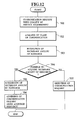
- sub-resource utilization is a case in which the division of the communication resource into the sub-resources r i is fixed, in which the packet exchanger 10 is operated according to a flow chart of Fig. 8 as follows.
- the communication resource such as a bandwidth, buffer capacity or both is divided up into N distinct sub-resources r i , either physically or logically, in correspondence with N different classes Ci, where each sub-resource r i is allocated to each class Ci without overlaps.
- a size of each sub-resource r i is predetermined according to the number of calls to be granted an admission to each sub-resource r i or expected to be granted an admission to each sub-resource r i .
- the packet exchanger 10 analyzes the class of this communication at the step 502, and evaluates the quality of service resulting from the admission for this communication request of call set up to an appropriate sub-resource r i at the step 503.
- a state of the traffic for this sub-resource r i is known to the packet exchanger 10, so that at the step 504, the packet exchanger 10 can determine whether it is possible to maintain the satisfactory quality of service for all communications of this class Ci after the admission of this communication request of call set up.
- the communication request of call set up is granted an admission only when the packet exchanger 10 judges that it is possible to satisfy the requirement for quality of service for all communications of this class Ci after the admission of this communication request of call set up. In such a case, the communication request of call set up is granted an admission at the step 505, whereas otherwise the communication request of call set up is rejected at the step 506.
- the priority control using communication speeds as a criterion for the priority levels may be incorporated in a form of either a preemptive priority control or a nonpreemptive priority control.
- a nonpreemptive priority control separate buffers are provided for different communication speed classes and the packets in a buffer for high speed communication are outputted unconditionally, whereas the packets in a buffer for low speed communication are not outputted until all the packets in buffers for the high speed communications are outputted.
- the packet exchanger 10 may be operated according to a flow chart of Fig. 9 as follows.
- the communication resource such as a bandwidth, buffer capacity or both is divided up into N distinct sub-resources r i , either physically or logically, in correspondence with N different classes Ci, where each sub-resource r i is allocated to each class Ci without overlaps.
- a size of each sub-resource r i is predetermined according to the number of calls to be granted an admission to each sub-resource r i or expected to be granted an admission to each sub-resource r i .
- the packet exchanger 10 analyzes the class of this communication at the step 512, and evaluates the necessary amount of communication resource for this communication request of call set up at the step 513.
- the amount of allocated communication resource for the already accommodated calls for this class is known to the packet exchanger 10, so that at the step 514, the packet exchanger 10 can determine whether it is possible to acquire the necessary amount of resource from the sub-resource allocated to this class.
- the communication request of call set up is granted an admission only when the packet exchanger 10 judges that it is possible to acquire the necessary amount of resource.
- the necessary amount of resource is acquired from the sub-resource allocated to this class at the step 515
- the communication request of call set up is granted an admission at the step 516
- the amount of allocated communication resource for the already accommodated calls for this class is renewed at the step 517, whereas otherwise the communication request of call set up is rejected at the step 518.
- the priority control using communication speeds as a criterion for the priority levels may be incorporated in a form of either a preemptive priority control or a nonpreemptive priority control.
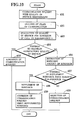
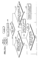
- sub-resource utilization is a case in which at least one of the sub-resources r i is utilized as a reserve, in which the packet exchanger 10 is operated according to a flow chart of Fig. 10 as follows.
- the reserve sub-resource r N+1 is not used when the communications can be handled by the other N sub-resources r i .
- the packet exchanger 10 analyzes the class of this communication at the step 602, and evaluates the quality of service resulting from the admission of this communication request of call set up to an appropriate sub-resource r i at the step 603.
- a state of the traffic for this sub-resource r i is known to the packet exchanger 10, so that at the step 604, the packet exchanger 10 can determine whether it is possible to satisfy the requirement for quality of service for all communications of this class Ci after the admission of this communication request of call set up.
- the communication request of call set up is granted an admission only when the packet exchanger 10 judges that it is possible to satisfy the requirement for quality of service for all communications of this class Ci after the admission of this communication request of call set up. In such a case, the communication request of call set up is granted an admission at the step 605.
- the deficient resource is supplemented from the reserve sub-resource r N+1 at the step 608, and the pending communication request of call set up is granted an admission by using this supplemented resource at the step 609.
- the resource supplemented from the reserve sub-resource r N+1 will be released again as soon as the need for such a supplement vanishes.
- the manner of acquiring supplement resource from the reserve sub-resource r N+1 may be either that in which each of the other N sub-resources r i attempts to acquire as much of the supplement as needed whenever the need arises, in which case even a whole of the reserve sub-resource r N+1 may be supplemented for one sub-resource r i if necessary, or else that in which an amount of supplement acquirable by one sub-resource r i is limited by a predetermined upper bound.
- the priority control using communication speeds as a criterion for the priority levels may be incorporated in a form of either a preemptive priority control or a nonpreemptive priority control.
- the packet exchanger 10 may be operated according to a flow chart of Fig. 11 as follows.
- the reserve sub-resource r N+1 is not used when the communications can be handled by the other N sub-resources r i .
- the packet exchanger 10 analyzes the class of this communication at the step 622, and evaluates the quality of service resulting from the admission of this communication request of call set up to an appropriate sub-resource r i at the step 623.
- the amount of allocated communication resource for the already accommodated calls for this class is known to the packet exchanger 10, so that at the step 624, the packet exchanger 10 can determine whether it is possible to acquire the necessary amount of resource from the sub-resource allocated to this class.
- the communication request of call set up is granted an admission only when the packet exchanger 10 judges that it is possible to acquire the necessary amount of resource.
- the necessary amount of resource is acquired from the sub-resource allocated to this class at the step 625, the communication request of call set up is granted an admission at the step 626, and the amount of allocated communication resource for the already accommodated calls for this class is renewed at the step 627.
- the deficient resource is supplemented from the reserve sub-resource r N+1 at the step 630, the pending communication request of call set up is granted an admission at the step 631, and the necessary resource is allocated to accommodate this call while the amount of the allocated resource is renewed at the step 632.
- the resource supplemented from the reserve sub-resource r N+1 will be released again as soon as the need for such a supplement vanishes.
- the manner of acquiring supplement resource from the reserve sub-resource r N+1 may be either that in which each of the other N sub-resources r i attempts to acquire as much of the supplement as needed whenever the need arises, in which case even a whole of the reserve sub-resource r N+1 may be supplemented for one sub-resource r i if necessary, or else that in which an amount of supplement acquirable by one sub-resource r i is limited by a predetermined upper bound.
- the priority control using communication speeds as a criterion for the priority levels may be incorporated in a form of either a preemptive priority control or a nonpreemptive priority control.
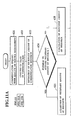
- Still another example of sub-resource utilization is a case in which the division of the communication resource into the sub-resources r i is made to be dynamically variable, in which the packet exchanger 10 is operated according to a flow chart of Fig. 12 as follows.
- an additional new communication request call of a particular communication class is generated, an attempt is made to acquire as much additional sub-resource of the communication resource as necessary to maintain the required quality of service.
- each sub-resource is still allocated uniquely to a particular class of communication as in the earlier cases, and not shared by different classes of communications.
- the packet exchanger 10 analyzes the class of this communication at the step 702.
- step 703 an amount of resource necessary to guarantee the required quality of service is estimated, and then whether such an amount of resource can be acquired from still unallocated portion of the communication resource is determined at the step 704.
- the necessary amount of resource is acquired from the still unallocated resource at the step 705, and the pending communication request of call set up is granted an admission by using this acquired resource at the step 706.
- the manner of acquiring necessary amount of resource can be similar to that of acquiring supplement resource from the reserve sub-resource r N+1 in the previous case.
- the priority control using communication speeds as a criterion for the priority levels may be incorporated in a form of either a preemptive priority control or a nonpreemptive priority control.
- any combination of the packet loss rate, transmission delay, and communication speed may be used as a parameter to classify the requirement for the quality of service.
- requirements such as 10 ⁇ 3, 10 ⁇ 6, and 10 ⁇ 8 may be employed.
- the communication speed may be classified either uniquely for an entire packet network by using an absolute value (bps) of the communication speed, or in terms of a ratio of the communication speed with respect to a size of the communication resource such as that of a bandwidth or a buffer capacity. More specifically a ratio of the communication speed with respect to a size of the communication resource may be a ratio of a transfer speed of a call with respect to a capacity of a multiplexed line, or a ratio of a buffer size required by a call with respect to a buffer size of a section to be multiplexed.
- a terminal generating a call itself may request the classes of the quality of service directly, or a terminal generating a call may only specify a requirement for the communication speed or the packet loss rate (either in terms of an absolute value or a class of an absolute value) which is subsequently transformed into the requirement for the quality of service with respect to the communication resource such as a multiplexed line or buffers.
- the same requirement for the class of the quality of service concerning the packet loss rate and/or the transmission delay may be taken differently according to a size of the sub-resource to be allocated, or in other words, different sub-resources of different sizes may be allocated to the same requirement of the class of the quality of service.
- the communication resource is the multiplexed line which is divided into a sub-resource r L of a large capacity and a sub-resource r S of a small capacity
- there can be a requirement of the quality of service which would belong to a class of low speed from a point of view of the sub-resource r L while which would belong to a class of high speed from a point of view of the sub-resource r S .
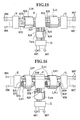
- virtual path groups 801, 802, 803, 804 and 805 are forming digital links between exchangers A and C, C and B, A and B, A and D, and D and B, respectively, where the exchanger A is connected to a terminal 806, while the exchangers B, C, and D are connected to terminals 807.
- bandwidths L A , L B , L C , and L D are allocated, while to the virtual path groups 801, 802, 803, 804, and 805, bandwidths L1 , L2, L3; L4, and L5, respectively, are allocated.
- the communication resource of bandwidths can be managed according to the present invention as follows.
- each one of the virtual path groups 801, 802, 803, 804, and 805 comprises three distinct virtual paths 811, 812, and 813 dividing the bandwidth allocated to each virtual path group in three without an overlap, which are provided in correspondence with three classes of the quality of service.
- a call with a particular requirement of the class of the quality of service is generated, whether one of the virtual paths 811, 812, and 813 corresponding to this requirement can grant an admission to the call is determined.
- the communication network of bandwidths can be managed according to the present invention in ordinary digital links between the exchangers.
- each digital link between exchangers E and F; F and G; and F and H is provided by triple channels 821, 822, and 823; 824, 825, and 826; and 827, 828, and 829, respectively.
- the exchanger E is connected to the terminal 806, the exchanger F is used as a transit node, and the exchangers G and H are connected to the terminals 807.
- the bandwidths are allocated to the digital links between the exchangers, such that a bandwidth L EF is allocated to a digital link of triple channels 821, 822, and 823; a bandwidth L FG is allocated to a digital link of triple channels 824, 825, and 826; and a bandwidth L FH is allocated to a digital link of triple channels 827, 828, and 829.
- the triple channels 821, 822, and 823; 824, 825, and 826; and 827, 828, and 829 divide the bandwidth of the digital link in three without an overlap, and are provided in correspondence with three classes of the quality of service. When a call with a particular requirement of the class of the quality of service is generated, whether one of these triple channels corresponding to this requirement can grant an admission to the call is determined.
- the bandwidths L EF and L FG are further divided into L EG and L EF1 , and L EG and L FG1 , respectively.
- the bandwidth L EG is allocated to a virtual path group 830 connecting the exchangers E and G directly, while the bandwidths L EF1 and L FG1 are covered by digital links of triple channels 831, 832, and 833; and 834, 835, and 836, respectively.
- the bandwidth is managed with respect to the virtual path 830 as in an example of Fig. 12 described above, while the bandwidths are managed with respect to the digital links of triple channels 831, 832, and 833; 834, 835, and 835; and 827, 828, and 829, as in an example of Fig. 13 described above.
- the packet loss rate can be estimated by several methods, the details of which will now be described.
- the call set up control for the is performed by using the probability density function which has a number of packets generated by each call as a variable.
- the traffic characteristic of each call is expressed in terms of the probability density function having a number of packets generated within a predetermined period of time as a variable
- the multiplexed traffic characteristic is obtained by taking convolution of the probability density function of each call
- the packet loss rate is estimated on a basis of this multiplexed traffic characteristic.
- all the packets to be entered are assumed to be of a fixed length, and each packet is assumed to take a unit time for being transferred to the multiplexed line.
- the packet network is to be notified of the maximum transfer speed M i of the packets of the call from an i-th terminal at the time of call set up request.
- the packet network is to be notified of a probability density function f i (n) for transferring n packets in a prescribed time T by the i-th terminal.
- the value of the probability density function f i (n) may be provided to the packet network directly, or it may be estimated by the packet network on a basis of various parameters specifying the traffic characteristic such as the peak bit rate and the average bit rate.
- the probability density function f i (n) in this case is estimated as follows.
- a probability density function f(n) for transferring n packets in a prescribed time T by the entire calls is set to an initial value "0" at the step 901.
- the probability density function f′(n) for transferring n packets in the prescribed time T by the entire calls of those which have already been set up and the requested one is obtained, as the convolution f(n)*f i (n) of the probability density function f(n) and the probability density function f i (n) at the step 903, and then the packet loss rate CLR′ for the entire calls of those which have already been set up and the requested one is estimated on a basis of the probability density function f′(n) at the step 904.
- this estimated packet loss rate CLR′ is compared with the packet loss rate CLR 0 ⁇ required by the entire calls of those which have already been set up and the requested one at the step 905.
- this call set up request is granted an admission at the step 906, and in such a case the probability density function f(n) is updated by the probability density function f′(n) at the step 907.
- the traffic characteristic of each call is expressed in terms of the maximum transfer speed of the call and the average transfer speed of the call
- the packet loss rate is estimated from these maximum transfer speed and the average transfer speed under the assumption that those packets arriving in excess of a predetermined number of packets transferrable within a prescribed period of time will be discarded
- the call set up control is carried out by comparing the packet loss rate so estimated with the packet loss rate required by the call.
- all the packets to be entered are assumed to be of a fixed length, and each packet is assumed to take a unit time for being transferred to the multiplexed line.
- the peak bit rate of the type-i call is denoted as V mi
- the average bit rate of the type-i calls is denoted as V ai .
- the peak bit rate of those calls which have the largest peak bit rate will be denoted as V m0 ⁇ .
- the period T can be expressed as an inverse of this largest peak bit rate V m0 ⁇ .
- the multiplexed line can transfer T packets during this period T, while each call transfer at most one packet during this period T.
- CLR 1 ⁇ T k T (k-T) ⁇ P k (1) where ⁇ is a load.
- N i of the type-i calls transfer N i T/T i packets during the period T.
- N i V mi /V m0 ⁇ may not necessarily takes an integer value
- the packet loss rate will actually be estimated by using a weighted average of [N i V mi /V m0 ⁇ ] and [N i V mi /V m0 ⁇ ]+1, where square brackets [x] denotes the largest integer value not greater than the argument x.
- R k (1, n i ) can be obtained once the P k is known.
- CLR i (n i ) the packet loss rate when the number of the type-i calls is equal to n i and the number of the type-j calls is given by the weighted average of n j and n j +1
- CLR i (n i +1) can also be expressed, by using the equation (3) above, as: so that from these equations (9) and (10) and the knowledge of CLR and R k (i, n i ), both CLR i (n i ) and CLR i (n i +1) can be obtained.
- CLR i (n i ) and CLR i (n i +1) can be obtained from the knowledge of a i0 ⁇ , a i1 , P k and CLR.
- 0 ⁇ j ⁇ T-1 ⁇ of j packets to arrive in the period T, the load ⁇ , and the current packet loss rate CLR are memorized, from which the new packet loss rate CLR′ will be derived as explained above, for the sake of the call set up control.
- 0 ⁇ j ⁇ T-1 ⁇ of j packets to arrive in the period T, the offered load ⁇ , and the current packet loss rate CLR are set.
- the new packet loss rate CLR′ obtained at the step 307 is compared with the packet loss rate requested by the entire calls including one just being requested, and whether to grant an admission or reject the call set up request is determined according to whether the required packet loss rate can be satisfied by granting an admission to the set up of this call.
- the process returns to the step 302 above to wait for the next request, whereas when the request is to be granted an admission, the memorized values of the numbers ⁇ N i ⁇ of the type-i calls currently set up, the probabilities ⁇ P j
- the high speed call is defined to be that for which a ratio of the maximum transfer speed of the call with respect to the transfer speed of the multiplexed line is greater than a prescribed value, while the low speed call is defined to be that which is not the high speed call.
- the first manner of the priority control is for a case in which the division of the communication resource into the sub-resources r i is fixed, in which the packet exchanger 10 is operated according to a flow chart of Fig. 19 as follows.
- the communication resource is divided up into N distinct sub-resources r i , either physically or logically, in correspondence with N different classes Ci, where each sub-resource r i is allocated to each class Ci without overlaps.
- a size of each sub-resource r i is predetermined according to the number of calls to be granted an admission to each sub-resource r i or expected to be granted an admission to each sub-resource r i .
- the packet exchanger 10 determines whether the this communication request of call set up is the high speed call or the low speed call at the step 101.
- the packet exchanger 10 can determine whether it is possible to maintain the satisfactory quality of service for all communications of this class Ci after the admission of this communication request of call set up, assuming that the peak bit rate is allocated for this communication request of call set up.
- the communication request of call set up is granted an admission only when the packet exchanger 10 judges that it is possible to satisfy the requirement for quality of service for all communications of this class Ci after the admission of this communication request of call set up. In such a case, the communication request of call set up is granted an admission at the step 103, whereas otherwise the communication request of call set up is rejected at the step 104.
- the packet exchanger 10 can determine whether it is possible to maintain the satisfactory quality of service for all communications of this class Ci after the admission of this communication request of call set up.
- the allocation of the peak bit rate for this communication request of call set up is not assumed.
- the communication request of call set up is granted an admission only when the packet exchanger 10 judges that it is possible to satisfy the requirement for quality of service for all communications of this class Ci after the admission of this communication request of call set up. In such a case, the communication request of call set up is granted an admission at the step 106, whereas otherwise the communication request of call set up is rejected at the step 104.
- the packet exchanger 10 may be operated to perform the priority control according to a flow chart of Fig. 20 as follows.
- the communication resource is divided up into N distinct sub-resources r i , either physically or logically, in correspondence with N different classes Ci, where each sub-resource r i is allocated to each class Ci without overlaps.
- a size of each sub-resource r i is predetermined according to the number of calls to be granted an admission to each sub-resource r i or expected to be granted an admission to each sub-resource r i .
- the packet exchanger 10 determines whether the this communication request of call set up is the high speed call or the low speed call at the step 111.
- the packet exchanger 10 can determine whether it is possible to acquire the necessary amount of resource from the sub-resource allocated to this class.
- the communication request of call set up is granted an admission only when the packet exchanger 10 judges that it is possible to acquire the necessary amount of resource.
- the communication request of call set up is granted an admission at the step 113, with the necessary amount of resource acquired from the sub-resource allocated to this class, and the amount of allocated communication resource for the already accommodated calls for this class is renewed at the step 114, whereas otherwise the communication request of call set up is rejected at the step 115.
- the packet exchanger 10 can determine whether it is possible to acquire the necessary amount of resource from the sub-resource allocated to this class.
- the communication request of call set up is granted an admission only when the packet exchanger 10 judges that it is possible to acquire the necessary amount of resource.
- the communication request of call set up is granted an admission at the step 118, with the necessary amount of resource acquired from the sub-resource allocated to this class, and the amount of allocated communication resource for the already accommodated calls for this class is renewed at the step 119, whereas otherwise the communication request of call set up is rejected at the step 115.
- Another manner of the priority control is for a case in which at least one of the sub-resources r i is utilized as a reserve, in which the packet exchanger 10 is operated according to a flow chart of Fig. 21 as follows.
- the reserve sub-resource r N+1 is not used when the communications can be handled by the other N sub-resources r i .
- the packet exchanger 10 determines whether the this communication request of call set up is the high speed call or the low speed call at the step 122.
- the packet exchanger 10 can determine whether it is possible to maintain the satisfactory quality of service for all communications of this class Ci after the admission of this communication request of call set up, assuming that the peak bit rate is allocated for this communication request of call set up.
- the communication request of call set up is granted an admission only when the packet exchanger 10 judges that it is possible to satisfy the requirement for quality of service for all communications of this class Ci after the admission of this communication request of call set up. In such a case, the communication request of call set up is granted an admission at the step 126.
- the necessary amount of resource is supplemented from the reserve sub-resource r N+1 at the step 125, and the pending communication request of call set up is granted an admission by using this supplemented resource at the step 126.
- the packet exchanger 10 can determine whether it is possible to maintain the satisfactory quality of service for all communications of this class Ci after the admission of this communication request of call set up.
- the allocation of the peak bit rate for this communication request of call set up is not assumed.
- the communication request of call set up is granted an admission only when the packet exchanger 10 judges that it is possible to satisfy the requirement for quality of service for all communications of this class Ci after the admission of this communication request of call set up. In such a case, the communication request of call set up is granted an admission at the step 128.
- the deficient resource is supplemented from the reserve sub-resource r N+1 at the step 131, and the pending communication request of call set up is granted an admission by using this supplemented resource at the step 132.
- the packet exchanger 10 may be operated to perform the priority control according to a flow chart of Fig. 22 as follows.
- the reserve sub-resource r N+1 is not used when the communications can be handled by the other N sub-resources r i .
- the packet exchanger 10 determines whether the this communication request of call set up is the high speed call or the low speed call at the step 141.
- the packet exchanger 10 can determine whether it is possible to acquire the necessary amount of resource from the sub-resource allocated to this class, assuming that the peak bit rate is allocated for this communication request of call set up.
- the communication request of call set up is granted an admission only when the packet exchanger 10 judges that it is possible to acquire the necessary amount of resource.
- the communication request of call set up is granted an admission at the step 145, with the necessary amount of resource acquired from the sub-resource allocated to this class, and the amount of allocated communication resource for the already accommodated calls for this class is renewed at the step 146.
- the necessary amount of resource is supplemented from the reserve sub-resource r N+1 at the step 144, and the pending communication request of call set up is granted an admission by using this supplemented resource at the step 145.
- the packet exchanger 10 can determine whether it is possible to acquire the necessary amount of resource from the sub-resource allocated to this class at the step 148.
- the communication request of call set up is granted an admission only when the packet exchanger 10 judges that it is possible to acquire the necessary amount of resource.
- the communication request of call set up is granted an admission at the step 153, with the necessary amount of resource acquired from the sub-resource allocated to this class, and the amount of allocated communication resource for the already accommodated calls for this class is renewed at the step 154.
- the necessary amount of resource is supplemented from the reserve sub-resource r N+1 at the step 150, the pending communication request of call set up is granted an admission by using this supplemented resource at the step 151, and the amount of allocated communication resource for the already accommodated calls for this class is renewed at the step 152.
- Still another manner of the priority control is for a case in which the division of the communication resource into the sub-resources r i is made to be dynamically variable, in which the packet exchanger 10 is operated according to a flow chart of Fig. 23 as follows.
- an additional new communication request call of a particular communication class is generated, an attempt is made to acquire as much additional sub-resource of the communication resource as necessary to maintain the required quality of service.
- each sub-resource is still allocated uniquely to a particular class of communication as in the earlier cases, and not shared by different classes of communications.
- the packet exchanger 10 determines whether the this communication request of call set up is the high speed call or the low speed call at the step 161.
- the packet exchanger 10 can determine whether it is possible to acquire the necessary amount of resource, assuming that the peak bit rate is allocated for this communication request of call set up.
- the communication request of call set up is granted an admission only when the packet exchanger 10 judges that it is possible to acquire the necessary amount of resource.
- the necessary amount of resource acquired at the step 163 the communication request of call set up is granted an admission at the step 164, and the amount of allocated communication resource for the already accommodated calls for this class is renewed at the step 165, whereas otherwise the communication request of call set up is rejected at the step 166.
- the communication request of call set up is granted an admission only when the packet exchanger 10 judges that it is possible to acquire the necessary amount of resource.
- the necessary amount of resource acquired at the step 169 the communication request of call set up is granted an admission at the step 170, and the amount of allocated communication resource for the already accommodated calls for this class is renewed at the step 171, whereas otherwise the communication request of call set up is rejected at the step 166.
- a priority control device 401 such as that shown in Fig. 24, which comprises a call type determining unit 402 for determining the call type of the packet inputted as either one of the high speed call and the low speed call, a high speed call buffer 403 for storing the packets generated by the call which has been determined as the high speed call by the call type determining unit 402, a low speed call buffer 404 for storing the packets generated by the call which has been determined as the low speed call by the call type determining unit 402, a priority control unit 405 for controlling the high and low speed call buffers 403 and 404 such that all the packets generated by the high speed call are transferred at the peak bit rate, with the priority over the packets generated by the low speed call, and an output interface 406 for outputting the packets from the high and low speed buffers 403 and 404 to the multiplexed line.
- a call type determining unit 402 for determining the call type of the packet inputted as either one of the high speed call and the low speed call
- the packet loss rate may be estimated by using the bandwidth obtained by subtracting the bandwidth allocated to the high speed call which is the same as the sum of the peak bit rates from the entire bandwidth resource of the multiplexed line.
- the packet loss rate may be estimated by using the entire bandwidth resource of the multiplexed line.
- the packet loss rate can be estimated by several methods, the details of which will now be described.
- the call set up control for the low speed call is performed by using the probability density function which has a number of packets generated by each call as a variable.
- the traffic characteristic of each low speed call is expressed in terms of the probability density function having a number of packets generated within a predetermined period of time as a variable
- the multiplexed traffic characteristic is obtained by taking convolution of the probability density function of each call
- the packet loss rate is estimated on a basis of this multiplexed traffic characteristic.
- all the packets to be entered are assumed to be of a fixed length, and each packet is assumed to take a unit time for being transferred to the multiplexed line.
- the call is determined as the high speed call when the ratio BR of the maximum transfer speed of the call with respect to the transfer speed of the multiplexed line is greater than a prescribed threshold value BR 0 ⁇ , whereas otherwise the call is determined as the low speed call.
- the packet network is to be notified of the maximum transfer speed M i of the packets of the call from an i-th terminal at the time of call set up request.
- This information may be provided when each terminal is connected to the packet network initially.
- the ratio BR i M i /C 0 ⁇ of the maximum transfer speed M i of the call with respect to the transfer speed of the multiplexed line C 0 ⁇ is calculated at the step 203, and whether the call is the high speed call or the low speed call is determined at the step 204 by comparing this BR i calculated at the step 203 with a prescribed threshold value BR 0 ⁇ .
- the call is determined as the high speed call when the ratio BR of the maximum transfer speed with respect to the speed of the multiplexed line is greater than a prescribed threshold value BR 0 ⁇ , whereas otherwise the call is determined as the low speed call, as already mentioned.
- this call set up request is rejected at the step 211.
- the packet loss rate CLR′ for the entire low speed calls including the requesting one is calculated as an average ⁇ f(n)CLR(1-(n/T)) of the packet loss rate CLR(1-(n/T)) obtained by assuming that the bandwidth of 1-(n/T) packets per unit time can be used at the probability f(n).
- this packet loss rate CLR′ is compared with the packet loss rate CLR 0 ⁇ required by the entire calls including the requesting call at the step 208.
- this call set up request is granted an admission at the step 209, and in such a case the probability f(n) is updated by the probability f′(n) at the step 210.
- the packet loss rate CLR(1-(n/T)) for the low speed calls with (1-(n/T)) packets per unit time of the bandwidth available is estimated under the assumption that those packets in excess of (T-n) packets in a given period T will be discarded.
- This assumption is equivalent to assuming that the bandwidth allocated to the high speed calls but considered to be not used by the high speed call is available to the low speed call.
- Such an assumption can be valid because the allocated bandwidth may not necessarily be utilized completely, even at the peak bit rate.
- the packet loss rate is effectively given an upper bound, which in turn improves the safety of the call set up control. Moreover, more efficient utilization of the communication resource is achieved while improving the quality of service for the low speed call.
- the call set up request for the low speed call is granted an admission only when the required packet loss rate can be satisfied by the packet loss rate estimated by assuming that the request is granted an admission, so that the quality of service for the low speed call can also be maintained.
Landscapes
- Engineering & Computer Science (AREA)
- Computer Networks & Wireless Communication (AREA)
- Signal Processing (AREA)
- Data Exchanges In Wide-Area Networks (AREA)
Abstract
Description
- The present invention relates to a packet network for communicating information in forms of packets in ATM (asynchronous transfer mode) in which each packet has a fixed packet length.
- In a conventional packet network, a communication resource of the network has been shared on an equal basis by all of the terminals of the network, so as to facilitate an efficient utilization of the communication resource by means of an effect of statistical multiplexing due to a sharing of a single communication resource among a plurality of communications.
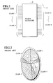
- Namely, as shown in Fig. 1, a communication resource provided by a
packet exchanger 1 of a packet network is shared by classes of communications classified into aclass 1 to a class N. In this case, as shown in Fig. 2, each one of individual sub-resources ri (i = 1, 2, ········ ) of the communication resource is shared by more than one classes of communications. - However, this manner of allocation of the communication resource causes a problem that qualities of service such as a packet loss rate (or a cell loss rate) and a transmission delay are uniformly deteriorated for all the classes of communications, when more than a manegeable number of packets are entered. This is a direct consequence of sharing of the communication resource among a plurality of communications on an equal basis.
- On the other hand, there has been a system of packet network in which a priority level is assigned to each class of communication in accordance with a requirement for a packet loss rate, so as to facilitate a so called priority control such that a certain degree of packet loss rate can be maintained.
- However, since the communication resource has been shared among communications of different priority levels, the actual packet loss rate depends on a relative amount of packets for these communications of different priority levels, so that it has been difficult to control the packet loss rate accurately.
- In addition, a lack of consideration for a communication speed of each communication has been making it difficult to maintain the packet loss rate below a certain level.
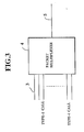
- As for a call set up control to be performed when a single communication resource is shared among a plurality of communications, there has been a system of packet network which achieves the call set up control as follows. Namely, as shown in Fig. 3, each one of
terminals 3 sends a call set up request individually to amultiplexer 4 of the packet network which is equipped with a multiplexed line 5, and themultiplexer 4 determines whether to set up the calls requested by judging whether it is possible to guarantee the satisfactory qualities of service to all the calls requested. Here, the qualities of service to be considered are a packet loss rate and a transmission delay. Thus, each time a call set up request is received from one of theterminals 3, themultiplexer 4 makes an assessment for the packet loss rate and the transmission delay from a known communication characteristics of each of theterminals 3, and judges whether it is possible to guarantee the satisfactory qualities of service to all the calls requesting to be set up in thepacket network 3. The requesting call is set up only when this criterion is satisfied. This manner of call set up control aims to achieve a more efficient utilization of the communication resource without sacrificing the qualities of service excessively. - However, conventionally, since the packet loss rate required by the calls or estimated by the
multiplexer 4 is in general an average packet loss rate evaluated for a extended period of time, so that the expected level of the packet loss rate may not be obtainable temporarily, even when the call set up control as described above is adopted. - For this reason, the conventional packet network completely ignored the temporal packet loss rate or sequential loss properties such as continuous packet losses. Therefore, when the calls possess burst property in which the packets are not necessarily discarded at random, rather continuous discarding of packets takes place, and even when the call set up control is performed to maintain the packet loss rate at certain level over an extended period of time, the temporal packet loss rate, especially that due to a continuous discarding of the packets, cannot be controlled at the satisfactory level. In particular, in a case of multiplexed calls occurring in a multiplexed line configuration of Fig. 3, a number of packets to be continuously discarded becomes overwhelmingly greater for high speed calls than for low speed calls, because for the high speed calls, as many packets as being transferred during a bursty period will be discarded continuously.
- Furthermore, in a packet network, a state of traffic varies with time. For this reason, in order to maintain a certain quality of service for each call, it is necessary to judge whether to set up a call or not in accordance with an estimate for the quality of service for a case of setting up a new call, estimated on a basis of a current state of traffic and an available communication resource.
- An example of a conventional method to achieve this is that in which the packet loss rate is evaluated by using a burst overflow rate. In this method, it is assumed that when a sum of the maximum speeds to send out the packets exceeds the capacity of the multiplexed line, such exceeding ones are discarded, and the packet loss rate is estimated from a probability for occurrence of such a discarding which is derived from a ratio of the maximum transfer speed and an average transfer speed of each call. Now, this method of estimating the packet loss rate using the burst overflow rate is known to require an enormous amount of calculation in a case in which the packet network is to deal with numerous types of calls. This amount of calculation in fact becomes so much for a practical situation that this method itself becomes rather impractical to implement.
- It is therefore an object of the present invention to provide a packet network in which the qualities of service can be maintained for different communications of different classes of requirement for quality of service.
- It is another object of the present invention to provide a packet network in which the qualities of service can be maintained regardless of types of calls and data.
- It is another object of the present invention to provide a packet network in which the packet loss rate can be estimated with a reduced amount of calculation.
- According to one aspect of the present invention there is provided a method of communication resource allocation in a packet network, comprising the steps of: subdividing a communication resource of the packet network into a plurality of sub-resources in correspondence with communications classified into a plurality of communication classes; allocating one of the sub-resources to each one of the communication classes; and controlling an amount of communications within each sub-resource independently, such that a quality of service required by the communications to which each sub-resource is allocated can be satisfied within each sub-resource.
- According to another aspect of the present invention there is provided a method of call set up control in a packet network, comprising the steps of: distinguishing first type of calls for which a ratio of a maximum transfer speed of each call with respect to a transfer speed of multiplexed line of the packet network is greater than a predetermined threshold value, and second type of calls which are not the first type of calls; and performing a priority control to favor the first type of calls over the second type of calls such that all packets of the first type of calls are transferred before any packet of the second type of calls.
- According to another aspect of the present invention there is provided a call set up control device in a packet network, comprising: means for distinguishing first type of calls for which a ratio of a maximum transfer speed of each call with respect to a transfer speed of multiplexed line of the packet network is greater than a predetermined threshold value, and second type of calls which are not the first type of calls; and means for performing a priority control to favor the first type of calls over the second type of calls such that all packets of the first type of calls are transferred before any packet of the second type of calls.
- Other features and advantages of the present invention will become apparent from the following description taken in conjunction with the accompanying drawings.
-
- Fig. 1 is a schematic diagram of one example of a conventional packet network.
- Fig. 2 is a diagram for explaining a sharing of a communication resource by a plurality of classes of communications in the packet network of Fig. 1.
- Fig. 3 is a schematic diagram of another example of a conventional packet network including a multiplexed line.
- Fig. 4 is a schematic diagram of one embodiment of a packet network according to the present invention.
- Fig. 5 is a diagram for explaining a sharing of a communication resource by a plurality of classes of communications in the packet network of Fig. 4.
- Fig. 6 is a buffer configuration for the packet network of Fig. 4 without the priority control.
- Fig. 7 is a buffer configuration for the packet network of Fig. 4 with the priority control.
- Fig. 8 is a flow chart for one possible operation of the packet network of Fig. 4.
- Fig. 9 is a flow chart for another possible operation of the packet network of Fig. 4.
- Fig. 10 is a flow chart for another possible operation of the packet network of Fig. 4.
- Fig. 11 is a flow chart for another possible operation of the packet network of Fig. 4.
- Fig. 12 is a flow chart for another possible operation of the packet network of Fig. 4.
- Fig. 13 is a schematic block diagram for an exemplary configuration for the packet network of Fig. 4 using virtual paths.
- Fig. 14 is a detail view of a virtual path in the configuration of Fig. 11.
- Fig. 15 is a schematic block diagram for an exemplary configuration for the packet network of Fig. 4 using ordinary digital links.
- Fig. 16 is a schematic block diagram for an exemplary configuration for the packet network of Fig. 4 using a virtual path and ordinary digital links.
- Fig. 17 is a flow chart for the call set up control without priority control, to be performed in the packet network of Fig. 4.
- Fig. 18 is a flow chart for one method of estimating the packet loss rate in the call set up control according to the flow chart of Figs. 17, and 19 to 23.
- Fig. 19 is a flow chart for one possible operation of the call set up control with priority control, to be performed in the packet network of Fig. 4.
- Fig. 20 is a flow chart for another possible operation of the call set up control with priority control, to be performed in the packet network of Fig. 4.
- Fig. 21 is a flow chart for another possible operation of the call set up control with priority control, to be performed in the packet network of Fig. 4.
- Fig. 22 is a flow chart for another possible operation of the call set up control with priority control, to be performed in the packet network of Fig. 4.
- Fig. 23 is a flow chart for another possible operation of the call set up control with priority control, to be performed in the packet network of Fig. 4.
- Fig. 24 is a schematic block diagram of a priority control device to perform the priority control according to the flow chart of Figs. 19 to 23.
- Fig. 25 is a flow chart for one method of estimating the packet loss rate in the call set up control with priority control according to the flow chart of Figs. 19 to 23.
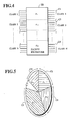
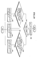
- Referring now to Fig. 4, there is shown one embodiment of a packet exchanger for a packet network according to the present invention.
- In this embodiment, a communication resource such as a bandwidth or a buffer capacity of the
packet exchanger 10 is divided up into a plurality (N in number) of mutually independent sub-resources ri (i = 1, 2, ········ , N) in correspondence with a plurality (N in number) of classes of communications C1 (class 1) to CN (class N), where an amount of calls accommodated by each sub-resource ri is controlled, so as to maintain a certain quality of service at satisfactory level. - Accordingly, as shown in Fig. 5, each sub-resource ri is exclusively allocated to one class of communication, and the call set up control is performed with respect to each sub-resource ri independently, so that the quality of service can be maintained at a desired level within each sub-resource ri.
- As a consequence, the quality of service obtainable within each sub-resource can easily be evaluated by classifying the communications according to the value of the packet loss rate required by each call, allocating different sub-resources for communications of different packet loss rates, and performing the call set up control with respect to each sub-resource separately.
- Also, even when more than manageable number of packets are accommodated by one particular sub-resource ri, the satisfactory quality of service can still be maintained at the other sub-resources.
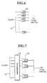
- In a case of not performing the priority control within each class Ci, the
packet exchanger 10 operates, as shown in Fig. 6, such that each communications of each class Ci is connected through abuffer 11 to each one of independent core switches (not shown) separately, so as to control each communication completely independently from other communications. - On the other hand, in a case of performing the priority control within each class Ci, input buffers of the
packet exchanger 10 operates, as shown in Fig. 7, such that the communications of the class Ci are connected through adistributor 12 to priority control buffers 13, before being given to a common core switch (not shown), so that the priority control can be achieved by means of the priority control buffers 13. - Furthermore, the
packet exchanger 10 can be operated in various different manners, according to different manners of treating the sub-resources ri of the communication resource. - One example of sub-resource utilization is a case in which the division of the communication resource into the sub-resources ri is fixed, in which the
packet exchanger 10 is operated according to a flow chart of Fig. 8 as follows. - Namely, in this case, the communication resource such as a bandwidth, buffer capacity or both is divided up into N distinct sub-resources ri, either physically or logically, in correspondence with N different classes Ci, where each sub-resource ri is allocated to each class Ci without overlaps. Here, a size of each sub-resource ri is predetermined according to the number of calls to be granted an admission to each sub-resource ri or expected to be granted an admission to each sub-resource ri.
- Now, in response to a communication request of call set up accompanied by a quality of service requirement generated at the
step 501, thepacket exchanger 10 analyzes the class of this communication at thestep 502, and evaluates the quality of service resulting from the admission for this communication request of call set up to an appropriate sub-resource ri at thestep 503. - At this point, a state of the traffic for this sub-resource ri is known to the
packet exchanger 10, so that at thestep 504, thepacket exchanger 10 can determine whether it is possible to maintain the satisfactory quality of service for all communications of this class Ci after the admission of this communication request of call set up. - The communication request of call set up is granted an admission only when the
packet exchanger 10 judges that it is possible to satisfy the requirement for quality of service for all communications of this class Ci after the admission of this communication request of call set up. In such a case, the communication request of call set up is granted an admission at thestep 505, whereas otherwise the communication request of call set up is rejected at thestep 506. - In this operation, the priority control using communication speeds as a criterion for the priority levels may be incorporated in a form of either a preemptive priority control or a nonpreemptive priority control. For example, in a case of a nonpreemptive priority control, separate buffers are provided for different communication speed classes and the packets in a buffer for high speed communication are outputted unconditionally, whereas the packets in a buffer for low speed communication are not outputted until all the packets in buffers for the high speed communications are outputted.
- Alternatively, in this case in which the division of the communication resource into the sub-resources ri is fixed, the
packet exchanger 10 may be operated according to a flow chart of Fig. 9 as follows. - Namely, here, the communication resource such as a bandwidth, buffer capacity or both is divided up into N distinct sub-resources ri, either physically or logically, in correspondence with N different classes Ci, where each sub-resource ri is allocated to each class Ci without overlaps. Here, a size of each sub-resource ri is predetermined according to the number of calls to be granted an admission to each sub-resource ri or expected to be granted an admission to each sub-resource ri.
- Now, in response to a communication request of call set up accompanied by a quality of service requirement generated at the
step 511, thepacket exchanger 10 analyzes the class of this communication at thestep 512, and evaluates the necessary amount of communication resource for this communication request of call set up at thestep 513. - At this point, the amount of allocated communication resource for the already accommodated calls for this class is known to the
packet exchanger 10, so that at thestep 514, thepacket exchanger 10 can determine whether it is possible to acquire the necessary amount of resource from the sub-resource allocated to this class. - The communication request of call set up is granted an admission only when the
packet exchanger 10 judges that it is possible to acquire the necessary amount of resource. In such a case, the necessary amount of resource is acquired from the sub-resource allocated to this class at thestep 515, the communication request of call set up is granted an admission at thestep 516, and the amount of allocated communication resource for the already accommodated calls for this class is renewed at thestep 517, whereas otherwise the communication request of call set up is rejected at thestep 518. - As in the previous case, in this operation, the priority control using communication speeds as a criterion for the priority levels may be incorporated in a form of either a preemptive priority control or a nonpreemptive priority control.
- Another example of sub-resource utilization is a case in which at least one of the sub-resources ri is utilized as a reserve, in which the
packet exchanger 10 is operated according to a flow chart of Fig. 10 as follows. - Namely, in this case, the communication resource is divided up into N+1 distinct sub-resources rj (j=1, 2, ········ N, N+1), either physically or logically, in correspondence with N different classes Ci (i=1, 2, ········ , N), where each sub resource ri is allocated to each class Ci without overlaps, while one additional sub-resource rN+1, is left as a reserve. Here, the reserve sub-resource rN+1 is not used when the communications can be handled by the other N sub-resources ri.
- Now, in response to a communication request of call set up accompanied by a quality of service requirement generated at the
step 601, thepacket exchanger 10 analyzes the class of this communication at thestep 602, and evaluates the quality of service resulting from the admission of this communication request of call set up to an appropriate sub-resource ri at thestep 603. - At this point, a state of the traffic for this sub-resource ri is known to the
packet exchanger 10, so that at thestep 604, thepacket exchanger 10 can determine whether it is possible to satisfy the requirement for quality of service for all communications of this class Ci after the admission of this communication request of call set up. - The communication request of call set up is granted an admission only when the
packet exchanger 10 judges that it is possible to satisfy the requirement for quality of service for all communications of this class Ci after the admission of this communication request of call set up. In such a case, the communication request of call set up is granted an admission at thestep 605. - On the other hand, in this case, when the
packet exchanger 10 judges that it is not possible to satisfy the requirement for quality of service for all communications of this class Ci after the admission of this communication request of call set up, a deficiency in amount of resource necessary to guarantee the required quality of service is estimated at thestep 606, and then whether such an amount of resource can be supplemented from the reserve sub-resource rN+1 is determined at thestep 607. - If so, the deficient resource is supplemented from the reserve sub-resource rN+1 at the
step 608, and the pending communication request of call set up is granted an admission by using this supplemented resource at thestep 609. The resource supplemented from the reserve sub-resource rN+1 will be released again as soon as the need for such a supplement vanishes. - Otherwise, the pending communication request of call set up is rejected at the
step 610. - The manner of acquiring supplement resource from the reserve sub-resource rN+1 may be either that in which each of the other N sub-resources ri attempts to acquire as much of the supplement as needed whenever the need arises, in which case even a whole of the reserve sub-resource rN+1 may be supplemented for one sub-resource ri if necessary, or else that in which an amount of supplement acquirable by one sub-resource ri is limited by a predetermined upper bound.
- As in the earlier cases, in this operation, the priority control using communication speeds as a criterion for the priority levels may be incorporated in a form of either a preemptive priority control or a nonpreemptive priority control.
- Alternatively, in this case in which at least one of the sub-resources ri is utilized as a reserve, the
packet exchanger 10 may be operated according to a flow chart of Fig. 11 as follows. - Namely, in this case, the communication resource is divided up into N+1 distinct sub-resources rj (j=1, 2, ········ N, N+1), either physically or logically, in correspondence with N different classes Ci (i=1, 2, ········ , N), where each sub-resource ri is allocated to each class Ci without overlaps, while one additional sub-resource rN+1 is left as a reserve. Here, the reserve sub-resource rN+1 is not used when the communications can be handled by the other N sub-resources ri.
- Now, in response to a communication request of call set up accompanied by a quality of service requirement generated at the
step 621, thepacket exchanger 10 analyzes the class of this communication at thestep 622, and evaluates the quality of service resulting from the admission of this communication request of call set up to an appropriate sub-resource ri at thestep 623. - At this point, the amount of allocated communication resource for the already accommodated calls for this class is known to the
packet exchanger 10, so that at thestep 624, thepacket exchanger 10 can determine whether it is possible to acquire the necessary amount of resource from the sub-resource allocated to this class. - The communication request of call set up is granted an admission only when the
packet exchanger 10 judges that it is possible to acquire the necessary amount of resource. In such a case, the necessary amount of resource is acquired from the sub-resource allocated to this class at thestep 625, the communication request of call set up is granted an admission at thestep 626, and the amount of allocated communication resource for the already accommodated calls for this class is renewed at thestep 627. - On the other hand, in this case, when the
packet exchanger 10 judges that it is not possible to acquire the necessary amount of resource from the sub-resource allocated to this class, a deficiency in amount of resource is estimated at thestep 628, and then whether such an amount of resource can be supplemented from the reserve sub-resource rN+1 is determined at thestep 629. - If so, the deficient resource is supplemented from the reserve sub-resource rN+1 at the
step 630, the pending communication request of call set up is granted an admission at thestep 631, and the necessary resource is allocated to accommodate this call while the amount of the allocated resource is renewed at thestep 632. The resource supplemented from the reserve sub-resource rN+1 will be released again as soon as the need for such a supplement vanishes. - Otherwise, the pending communication request of call set up is rejected at the
step 633. - As before, the manner of acquiring supplement resource from the reserve sub-resource rN+1 may be either that in which each of the other N sub-resources ri attempts to acquire as much of the supplement as needed whenever the need arises, in which case even a whole of the reserve sub-resource rN+1 may be supplemented for one sub-resource ri if necessary, or else that in which an amount of supplement acquirable by one sub-resource ri is limited by a predetermined upper bound.
- Also, as in the earlier cases, in this operation, the priority control using communication speeds as a criterion for the priority levels may be incorporated in a form of either a preemptive priority control or a nonpreemptive priority control.
- Still another example of sub-resource utilization is a case in which the division of the communication resource into the sub-resources ri is made to be dynamically variable, in which the
packet exchanger 10 is operated according to a flow chart of Fig. 12 as follows. - Namely, in this case, the communication resource is not divided up into the sub-resources ri (i=1, 2, ········ , N) in advance, but an attempt is made to allocate as much sub-resource of the communication resource as necessary to each class of communication whenever the communication request of call set up of a particular communication class is generated. When an additional new communication request call of a particular communication class is generated, an attempt is made to acquire as much additional sub-resource of the communication resource as necessary to maintain the required quality of service. Here, however, each sub-resource is still allocated uniquely to a particular class of communication as in the earlier cases, and not shared by different classes of communications.
- Now, in response to a communication request of call set up accompanied by a quality of service requirement generated at the
step 701, thepacket exchanger 10 analyzes the class of this communication at thestep 702. - Then, at the
step 703, an amount of resource necessary to guarantee the required quality of service is estimated, and then whether such an amount of resource can be acquired from still unallocated portion of the communication resource is determined at thestep 704. - If so, the necessary amount of resource is acquired from the still unallocated resource at the
step 705, and the pending communication request of call set up is granted an admission by using this acquired resource at thestep 706. - Otherwise, the pending communication request of call set up is rejected at the
step 707. - The manner of acquiring necessary amount of resource can be similar to that of acquiring supplement resource from the reserve sub-resource rN+1 in the previous case.
- Also, as in the previous cases, the priority control using communication speeds as a criterion for the priority levels may be incorporated in a form of either a preemptive priority control or a nonpreemptive priority control.
- In the embodiments described above, any combination of the packet loss rate, transmission delay, and communication speed may be used as a parameter to classify the requirement for the quality of service.
- For the packet loss rate, requirements such as 10⁻³, 10⁻⁶, and 10⁻⁸ may be employed.
- For the transmission delay, requirements of magnitudes of the transmission delay, or magnitudes of delay jitter may be employed.
- The communication speed may be classified either uniquely for an entire packet network by using an absolute value (bps) of the communication speed, or in terms of a ratio of the communication speed with respect to a size of the communication resource such as that of a bandwidth or a buffer capacity. More specifically a ratio of the communication speed with respect to a size of the communication resource may be a ratio of a transfer speed of a call with respect to a capacity of a multiplexed line, or a ratio of a buffer size required by a call with respect to a buffer size of a section to be multiplexed.
- As for the request of the class of the quality of service, a terminal generating a call itself may request the classes of the quality of service directly, or a terminal generating a call may only specify a requirement for the communication speed or the packet loss rate (either in terms of an absolute value or a class of an absolute value) which is subsequently transformed into the requirement for the quality of service with respect to the communication resource such as a multiplexed line or buffers.
- Also, in a case of utilizing the communication speed, the same requirement for the class of the quality of service concerning the packet loss rate and/or the transmission delay may be taken differently according to a size of the sub-resource to be allocated, or in other words, different sub-resources of different sizes may be allocated to the same requirement of the class of the quality of service. For example, when the communication resource is the multiplexed line which is divided into a sub-resource rL of a large capacity and a sub-resource rS of a small capacity, there can be a requirement of the quality of service which would belong to a class of low speed from a point of view of the sub-resource rL while which would belong to a class of high speed from a point of view of the sub-resource rS. Also, there can be two requirements of the quality of service req1 and req2 both of which would belong to a class of low speed from a point of view of the sub-resource rL while req1 would belong to a class of high speed and req2 would belong to a class of low speed from a point of view of the sub-resource rS.
- Referring now to Fig. 11, an exemplary case of using the bandwidth as the communication network will be described.
- In Fig. 11,
virtual path groups terminals 807. To the exchangers A, B, C, and D, bandwidths LA, LB, LC, and LD, respectively, are allocated, while to thevirtual path groups
LA = L₁ + L₃ + L₄
LB = L₂ + L₃ + L₅
LC = L₁ + L₂
LD= L₄ + L₅ - In these
virtual path groups - Namely, as shown in Fig. 12, each one of the
virtual path groups virtual paths virtual paths - Similarly, as shown in Fig. 13, the communication network of bandwidths can be managed according to the present invention in ordinary digital links between the exchangers.
- In Fig. 13, each digital link between exchangers E and F; F and G; and F and H is provided by
triple channels terminals 807. The bandwidths are allocated to the digital links between the exchangers, such that a bandwidth LEF is allocated to a digital link oftriple channels triple channels triple channels triple channels - Moreover, the examples of Fig. 12 and Fig. 13 described above can be mixed, as shown in Fig. 14.
- In Fig. 14, the bandwidths LEF and LFG are further divided into LEG and LEF1, and LEG and LFG1, respectively. The bandwidth LEG is allocated to a
virtual path group 830 connecting the exchangers E and G directly, while the bandwidths LEF1 and LFG1 are covered by digital links oftriple channels virtual path 830 as in an example of Fig. 12 described above, while the bandwidths are managed with respect to the digital links oftriple channels - Now, the call set up control without the priority control utilizing the communication speeds according to the present invention will be described in detail.
- Here, the packet loss rate can be estimated by several methods, the details of which will now be described.
- First of all, there is a method utilizing the probability density function, in which the call set up control for the is performed by using the probability density function which has a number of packets generated by each call as a variable. Namely, the traffic characteristic of each call is expressed in terms of the probability density function having a number of packets generated within a predetermined period of time as a variable, the multiplexed traffic characteristic is obtained by taking convolution of the probability density function of each call, and the packet loss rate is estimated on a basis of this multiplexed traffic characteristic. This method has been described by the present inventors in Japanese Patent Application No. 1-23071(1989).
- Secondly, a method in which the packet loss rate is estimated on a basis of the peak bit rate and the average bit rate is also known.
- In contrast, there is a method utilizing the bandwidth allocation at the peak bit rate alone, in which the call set up control is performed by utilizing the bandwidth allocation at the peak bit rate.
- Referring now to Fig 17, a detail of the method utilizing the probability density function will be described. This method is carried out according to the flow chart of Fig. 17, as follows.
- Here, all the packets to be entered are assumed to be of a fixed length, and each packet is assumed to take a unit time for being transferred to the multiplexed line.
- Also, in this method, the packet network is to be notified of the maximum transfer speed Mi of the packets of the call from an i-th terminal at the time of call set up request.
- In this method, the packet network is to be notified of a probability density function fi(n) for transferring n packets in a prescribed time T by the i-th terminal. The value of the probability density function fi(n) may be provided to the packet network directly, or it may be estimated by the packet network on a basis of various parameters specifying the traffic characteristic such as the peak bit rate and the average bit rate. In a case of estimating the probability density function fi(n) from the peak bit rate Vmi and the average bit rate Vai of the i-th call, it is sufficient to consider the worst situation in which the packet loss rate becomes greatest. Thus, the probability density function fi(n) in this case is estimated as follows.

- Now, initially, when there is no terminal connected to the packet network, a probability density function f(n) for transferring n packets in a prescribed time T by the entire calls is set to an initial value "0" at the
step 901. - Then, when the call set up request is made from the i-th terminal at the
step 902, the probability density function f′(n) for transferring n packets in the prescribed time T by the entire calls of those which have already been set up and the requested one is obtained, as the convolution f(n)*fi(n) of the probability density function f(n) and the probability density function fi(n) at thestep 903, and then the packet loss rate CLR′ for the entire calls of those which have already been set up and the requested one is estimated on a basis of the probability density function f′(n) at thestep 904. - Then, this estimated packet loss rate CLR′ is compared with the packet loss rate CLR0̸ required by the entire calls of those which have already been set up and the requested one at the
step 905. - If the packet loss rate CLR′ is less than the packet loss rate CLR0̸, this call set up request is granted an admission at the
step 906, and in such a case the probability density function f(n) is updated by the probability density function f′(n) at thestep 907. - Otherwise, this call set up request is rejected at the
step 908. - Then the process returns to the
step 902, so that the same procedure will be carried out with respect to the next call set up request. - Next, a detail of the method utilizing the peak bit rate and the average bit rate will be described.
- In this method utilizing the peak bit rate and the average bit rate, the traffic characteristic of each call is expressed in terms of the maximum transfer speed of the call and the average transfer speed of the call, the packet loss rate is estimated from these maximum transfer speed and the average transfer speed under the assumption that those packets arriving in excess of a predetermined number of packets transferrable within a prescribed period of time will be discarded, and the call set up control is carried out by comparing the packet loss rate so estimated with the packet loss rate required by the call.
- Here, as before, all the packets to be entered are assumed to be of a fixed length, and each packet is assumed to take a unit time for being transferred to the multiplexed line.
- In this method, L types of calls are to be multiplexed, with a number of the type-i calls (i = 1, ········, L) being Ni. The peak bit rate of the type-i call is denoted as Vmi, and the average bit rate of the type-i calls is denoted as Vai. Among all the multiplexed calls, the peak bit rate of those calls which have the largest peak bit rate will be denoted as Vm0̸. The period T can be expressed as an inverse of this largest peak bit rate Vm0̸. Thus, the multiplexed line can transfer T packets during this period T, while each call transfer at most one packet during this period T. By estimating the packet loss rate under the assumption that those packets arriving in excess of T packets within the period T will be discarded, the estimated packet loss rate can always be greater than the actual packet loss rate, so that the quality of service can always be maintained at the satisfactory level.
- Now, the packet loss rate CLR is given by:
CLR = T(k-T)·Pk (1)
where ρ is a load. - In this expression,

- When one type-j call is newly set up, the new packet loss rate CLR′ will be given by:

ρ′ = p + Vaj
and Pk will also be renewed to Pk′ given by:
- On the other hand, when one type-j call is newly released, the new packet loss rate CLR′ will be given by:

ρ′ = ρ - Vaj
and Pk will also be renewed to Pk′ given by:
- Now, Ni of the type-i calls can transfer exactly Ni packets during a period of Ti = 1/Vmi at the speed of the peak bit rate Vmi . Thus, in effect, it can be regarded that Ni of the type-i calls transfer NiT/Ti packets during the period T. On the other hand, a single call of the largest peak bit rate Vm0̸ can transfer exactly one packets during the period T. Therefore, in effect, Ni of the type-i calls can be regarded as NiT/Ti = NiVmi/VmØ calls of the largest peak bit rate Vm0̸. Here, however, since a quantity NiVmi/Vm0̸ may not necessarily takes an integer value, the packet loss rate will actually be estimated by using a weighted average of [NiVmi/Vm0̸] and [NiVmi/Vm0̸]+1, where square brackets [x] denotes the largest integer value not greater than the argument x. The cases [NiVmi/Vm0̸] and [NiVmi/Vm0̸]+1 are weighted by probability weights ai0̸ and ai1, respectively, where ai0̸ and ai1 are given by the following expressions:

- The actual calculation are carried out as follows.
- Namely, by defining Rk(i, ni) as the probability for k packets to be transferred from the multiplexed calls when the number of the type-i calls is equal to ni = [NiVmi/Vm0̸] and the number of the type-j calls is given by the weighted average of nj = [NjVmj/Vm0̸] and nj+1, then Pk and Rk have the relationships:

- Here, since ai0̸ and ai1 are known, Rk(1, ni) can be obtained once the Pk is known.
- Now, by defining CLRi(ni) as the packet loss rate when the number of the type-i calls is equal to ni and the number of the type-j calls is given by the weighted average of nj and nj+1, the packet loss rate CLR can be given by:
CLR = ρ0̸ai0̸CLRi(ni) + ρ₁ai1CLRi(ni+1) (9)
where ρØ is the offered load when the number of the type-i calls is equal to ni and ρ₁ is the offered load when the number of the type-i calls is equal to ni+1. - On the other hand, CLRi(ni+1) can also be expressed, by using the equation (3) above, as:

- In other words, CLRi(ni) and CLRi(ni+1) can be obtained from the knowledge of ai0̸, ai1, Pk and CLR.
- Thus, when one type-i call is newly set up, in which case the number of the type-i call increases from Ni to Ni+1, if [NiVmi/Vm0̸] = ni = [(Ni+1)Vmi/Vm0̸] then CLR′ and Pk′ can be obtained by:

where
- On the other hand, if [NiVmi/Vm0̸] = ni and [(Ni+1)Vmi/Vm0̸] = ni+1, then:

- As an example, a case of L = 2 can explicitly be worked out as follows.
- Here, N₁ of the type-1 calls having the maximum transfer speed of Vm1 and the average transfer speed of Va1, and N₂ of the type-2 calls having the maximum transfer speed of Vm2 and the average transfer speed of Va2 are set up, where Vm1>Vm2 so that Vm0̸ = Vm1.
- In this case, when [NiVmi/Vm0̸] = N₁ = n₁ and [N₂Vm2 /Vm0̸] = n₂, the packet loss rate CLR is given by:

a20̸ = n₂+1-N₂Vm2/Vm1
a₂₁ = 1 - a20̸
and CLR(n₁, n₂) represents the packet loss rate when the number of the type-1 calls is n₁ and the number of type-2 calls is n₂. - Now, when the set up of the type-2 call, which is the low speed call, is requested, if [(N₂+1)Vm2/Vm0̸] = n₂, then the new packet loss rate CLR′ is given by:

a′20̸ = n₂+1-(N₂+1)Vm2/Vm1
a′₂₁ = 1 - a′20̸
In this case,
- On the other hand, when the set up of the type-2 call is requested, if [(N₂+1)Vm2/Vm0̸] = n₂+1, then the new packet loss rate CLR′ is given by:

a′20̸ = n₂+1-(N₂+1)Vm2/Vm1
a′₂₁ = 1 - a′20̸ - This method just described in detail can actually be carried out according to the flow chart of Fig. 18, as follows.
- Here, the numbers {Ni} of the type-i calls currently set up, the probabilities {Pj|0≦j≦T-1} of j packets to arrive in the period T, the load ρ, and the current packet loss rate CLR are memorized, from which the new packet loss rate CLR′ will be derived as explained above, for the sake of the call set up control.
- Thus, first, at the
step 301, the initial values for the numbers {Ni} of the type-i calls currently set up, the probabilities {Pj|0≦j≦T-1} of j packets to arrive in the period T, the offered load ρ, and the current packet loss rate CLR are set. - Then, when the set up of the type-i call is requested at the
step 302, the probability Rj(i,ni ) = Rj(i, [NiVmi /Vm0̸]) is read out at thestep 303, and from this probability Rj(i,ni) = Rj(i,[NiVmi/Vm0̸]), the packet loss rate CLRi(ni) = CLRi ([NiVmi/Vm0̸]) for the case in which the number of the type-i calls is ni and the packet loss rate CLR(ni+1) = CLR([NiVmi/Vm0̸]+1) for the case in which the number of the type-i calls is ni+1 are derived at thestep 304. - Next, at the
step 305, values of [NiVmi/Vm0̸] and [(Ni+1)Vmi/Vm0̸] are compared in order to distinguish the case in which [(Ni+1)Vmi/Vm0̸ = ni and the case in which [(Ni+1)Vmi/Vm0̸] = ni+1. - When the values of [NiVmi/Vm0̸] and [(Ni+1)Vmi/Vm0̸] are equal, i.e., when [(Ni+1)Vmi/Vm0̸] = ni , the new packet loss rate CLR′ is obtained at the
step 307, from CLRi(ni) = CLRi ([NiVmi/Vm0̸]) and CLRi(ni+1) = CLRi([NiVmi/Vm0̸]+1) derived at thestep 304. - Whereas when the values of [NiVmi/Vm0̸] and [(Ni+1)Vmi/Vm0̸] are not equal, i.e., when [(Ni+1)Vmi/Vm0̸] = ni+1, CLR(ni+1) = CLR([(Ni+1)Vmi/Vm0̸]) for the case in which the number of the type-i calls is ni +1 and the packet loss rate CLR(ni+2) = CLR([(Ni+1)Vmi/Vm0̸]+1) for the case in which the number of the type-i calls is ni+2 are re-derived for this case at the
step 306, and the new packet loss rate CLR′ is obtained at thestep 307, from CLRi(ni+1) = CLRi([(Ni+1)Vmi/Vm0̸]) and CLRi(ni+2) = CLRi([(Ni+1)Vmi/Vm0̸]1+1) derived at thestep 306. - Then at the
step 308, the new packet loss rate CLR′ obtained at thestep 307 is compared with the packet loss rate requested by the entire calls including one just being requested, and whether to grant an admission or reject the call set up request is determined according to whether the required packet loss rate can be satisfied by granting an admission to the set up of this call. - When the request is to be rejected, the process returns to the
step 302 above to wait for the next request, whereas when the request is to be granted an admission, the memorized values of the numbers {Ni} of the type-i calls currently set up, the probabilities {Pj|0≦j≦T-1} of j packets to arrive in the period T, the current packet loss rate CLR, and the current offered load ρ are renewed to new values obtained by the calculations in the process described above. - Here, there is no need to calculate all the probabilities Pj for all possible combinations of types of calls, so that the amount of calculation will not increase even when the number of call types increases.
- Now, the priority control utilizing the communication speeds in the packet network according to the present invention will be described in detail.
- According to the present invention, the high speed call is defined to be that for which a ratio of the maximum transfer speed of the call with respect to the transfer speed of the multiplexed line is greater than a prescribed value, while the low speed call is defined to be that which is not the high speed call.
- Then, when the sum of the maximum transfer speed of the high speed calls is not greater than the transfer speed of the multiplexed line, all the packets generated by the high speed calls are transferred at a peak bit rate, i.e., at the maximum transfer speed. By means of this, the quality of service for the high speed calls, which tended to be poorer conventionally, can be secured to be at the satisfactory level.
- More specifically, such a priority control can be achieved in several different manners, which will now be described in detail.
- The first manner of the priority control is for a case in which the division of the communication resource into the sub-resources ri is fixed, in which the
packet exchanger 10 is operated according to a flow chart of Fig. 19 as follows. - Namely, in this case, the communication resource is divided up into N distinct sub-resources ri, either physically or logically, in correspondence with N different classes Ci, where each sub-resource ri is allocated to each class Ci without overlaps. Here, a size of each sub-resource ri is predetermined according to the number of calls to be granted an admission to each sub-resource ri or expected to be granted an admission to each sub-resource ri.
- Now, in response to a communication request of call set up accompanied by a quality of service requirement generated at the
step 100, thepacket exchanger 10 determines whether the this communication request of call set up is the high speed call or the low speed call at thestep 101. - At this point, a state of the traffic for this sub-resource ri is known to the
packet exchanger 10. - Thus, when the communication request of call set up is determined as the high speed call at the
step 101, next at thestep 102, thepacket exchanger 10 can determine whether it is possible to maintain the satisfactory quality of service for all communications of this class Ci after the admission of this communication request of call set up, assuming that the peak bit rate is allocated for this communication request of call set up. - The communication request of call set up is granted an admission only when the
packet exchanger 10 judges that it is possible to satisfy the requirement for quality of service for all communications of this class Ci after the admission of this communication request of call set up. In such a case, the communication request of call set up is granted an admission at thestep 103, whereas otherwise the communication request of call set up is rejected at thestep 104. - On the other hand, when the communication request of call set up is determined as the low speed call at the
step 101, next at thestep 105, thepacket exchanger 10 can determine whether it is possible to maintain the satisfactory quality of service for all communications of this class Ci after the admission of this communication request of call set up. Here, in contrast to the case of the high speed call, the allocation of the peak bit rate for this communication request of call set up is not assumed. - The communication request of call set up is granted an admission only when the
packet exchanger 10 judges that it is possible to satisfy the requirement for quality of service for all communications of this class Ci after the admission of this communication request of call set up. In such a case, the communication request of call set up is granted an admission at thestep 106, whereas otherwise the communication request of call set up is rejected at thestep 104. - Alternatively, for the case in which the division of the communication resource into the sub-resources ri is fixed, the
packet exchanger 10 may be operated to perform the priority control according to a flow chart of Fig. 20 as follows. - Namely, here again, the communication resource is divided up into N distinct sub-resources ri, either physically or logically, in correspondence with N different classes Ci, where each sub-resource ri is allocated to each class Ci without overlaps. Here, a size of each sub-resource ri is predetermined according to the number of calls to be granted an admission to each sub-resource ri or expected to be granted an admission to each sub-resource ri.
- Now, in response to a communication request of call set up accompanied by a quality of service requirement generated at the
step 110, thepacket exchanger 10 determines whether the this communication request of call set up is the high speed call or the low speed call at thestep 111. - At this point, the amount of allocated communication resource for the already accommodated calls for this class is known to the
packet exchanger 10. - Thus, when the communication request of call set up is determined as the high speed call at the
step 101, next at thestep 102, thepacket exchanger 10 can determine whether it is possible to acquire the necessary amount of resource from the sub-resource allocated to this class. - The communication request of call set up is granted an admission only when the
packet exchanger 10 judges that it is possible to acquire the necessary amount of resource. In such a case, the communication request of call set up is granted an admission at thestep 113, with the necessary amount of resource acquired from the sub-resource allocated to this class, and the amount of allocated communication resource for the already accommodated calls for this class is renewed at thestep 114, whereas otherwise the communication request of call set up is rejected at thestep 115. - On the other hand, when the communication request of call set up is determined as the low speed call at the
step 111, next at thestep 116, thepacket exchanger 10 can determine whether it is possible to acquire the necessary amount of resource from the sub-resource allocated to this class. - The communication request of call set up is granted an admission only when the
packet exchanger 10 judges that it is possible to acquire the necessary amount of resource. In such a case, the communication request of call set up is granted an admission at thestep 118, with the necessary amount of resource acquired from the sub-resource allocated to this class, and the amount of allocated communication resource for the already accommodated calls for this class is renewed at thestep 119, whereas otherwise the communication request of call set up is rejected at thestep 115. - Another manner of the priority control is for a case in which at least one of the sub-resources ri is utilized as a reserve, in which the
packet exchanger 10 is operated according to a flow chart of Fig. 21 as follows. - Namely, in this case, the communication resource is divided up into N+1 distinct sub-resources rj (j=1, 2, ········ N, N+1), either physically or logically, in correspondence with N different classes Ci (i=1, 2, ········ , N), where each sub resource ri is allocated to each class Ci without overlaps, while one additional sub-resource rN+1 is left as a reserve. Here, the reserve sub-resource rN+1 is not used when the communications can be handled by the other N sub-resources ri.
- Now, in response to a communication request of call set up accompanied by a quality of service requirement generated at the
step 121, thepacket exchanger 10 determines whether the this communication request of call set up is the high speed call or the low speed call at thestep 122. - At this point, a state of the traffic for this sub-resource ri is known to the
packet exchanger 10. - Thus, when the communication request of call set up is determined as the high speed call at the
step 122, next at thestep 123, thepacket exchanger 10 can determine whether it is possible to maintain the satisfactory quality of service for all communications of this class Ci after the admission of this communication request of call set up, assuming that the peak bit rate is allocated for this communication request of call set up. - The communication request of call set up is granted an admission only when the
packet exchanger 10 judges that it is possible to satisfy the requirement for quality of service for all communications of this class Ci after the admission of this communication request of call set up. In such a case, the communication request of call set up is granted an admission at thestep 126. - On the other hand, in this case, when the
packet exchanger 10 judges that it is not possible to satisfy the requirement for quality of service for all communications of this class Ci after the admission of this communication request of call set up, an amount of resource necessary to guarantee the required quality of service is estimated and whether such an amount of resource can be supplemented from the reserve sub-resource rN+1 is determined at thestep 124, assuming that the peak bit rate is allocated for this communication request of call set up. - If so, the necessary amount of resource is supplemented from the reserve sub-resource rN+1 at the
step 125, and the pending communication request of call set up is granted an admission by using this supplemented resource at thestep 126. - Otherwise, the pending communication request of call set up is rejected at the
step 133. - On the contrary, when the communication request of call set up is determined as the low speed call at the
step 122, next at thestep 127, thepacket exchanger 10 can determine whether it is possible to maintain the satisfactory quality of service for all communications of this class Ci after the admission of this communication request of call set up. Here, in contrast to the case of the high speed call, the allocation of the peak bit rate for this communication request of call set up is not assumed. - The communication request of call set up is granted an admission only when the
packet exchanger 10 judges that it is possible to satisfy the requirement for quality of service for all communications of this class Ci after the admission of this communication request of call set up. In such a case, the communication request of call set up is granted an admission at thestep 128. - On the other hand, in this case, when the
packet exchanger 10 judges that it is not possible to satisfy the requirement for quality of service for all communications of this class Ci after the admission of this communication request of call set up, a deficiency in amount of resource necessary to guarantee the required quality of service is estimated at thestep 129 and whether such an amount of resource can be supplemented from the reserve sub-resource rN+1 is determined at thestep 130. - If so, the deficient resource is supplemented from the reserve sub-resource rN+1 at the
step 131, and the pending communication request of call set up is granted an admission by using this supplemented resource at thestep 132. - Otherwise, the pending communication request of call set up is rejected at the
step 133. - Alternatively, for the case in which at least one of the sub-resources ri is utilized as a reserve, the
packet exchanger 10 may be operated to perform the priority control according to a flow chart of Fig. 22 as follows. - Namely, here again, the communication resource is divided up into N+1 distinct sub-resources rj (j=1, 2, ········ N, N+1), either physically or logically, in correspondence with N different classes Ci (i=1, 2, ········ , N) where each sub-resource ri is allocated to each class Ci without overlaps, while one additional sub-resource rN+1 is left as a reserve. Here, the reserve sub-resource rN+1 is not used when the communications can be handled by the other N sub-resources ri.
- Now, in response to a communication request of call set up accompanied by a quality of service requirement generated at the
step 140, thepacket exchanger 10 determines whether the this communication request of call set up is the high speed call or the low speed call at thestep 141. - At this point, the amount of allocated communication resource for the already accommodated calls for this class is known to the
packet exchanger 10. - Thus, when the communication request of call set up is determined as the high speed call at the
step 141, next at thestep 142, thepacket exchanger 10 can determine whether it is possible to acquire the necessary amount of resource from the sub-resource allocated to this class, assuming that the peak bit rate is allocated for this communication request of call set up. - The communication request of call set up is granted an admission only when the
packet exchanger 10 judges that it is possible to acquire the necessary amount of resource. In such a case, the communication request of call set up is granted an admission at thestep 145, with the necessary amount of resource acquired from the sub-resource allocated to this class, and the amount of allocated communication resource for the already accommodated calls for this class is renewed at thestep 146. - On the other hand, in this case, when the
packet exchanger 10 judges that it is not possible to acquire the necessary amount of resource from the sub-resource allocated to this class, an amount of resource necessary to guarantee the required quality of service is estimated and whether such an amount of resource can be supplemented from the reserve sub-resource rN+1 is determined at thestep 143, assuming that the peak bit rate is allocated for this communication request of call set up. - If so, the necessary amount of resource is supplemented from the reserve sub-resource rN+1 at the
step 144, and the pending communication request of call set up is granted an admission by using this supplemented resource at thestep 145. - Otherwise, the pending communication request of call set up is rejected at the
step 155. - On the contrary, when the communication request of call set up is determined as the low speed call at the
step 141, next, an amount of resource necessary to guarantee the required quality of service is estimated at thestep 147, and thepacket exchanger 10 can determine whether it is possible to acquire the necessary amount of resource from the sub-resource allocated to this class at thestep 148. - The communication request of call set up is granted an admission only when the
packet exchanger 10 judges that it is possible to acquire the necessary amount of resource. In such a case, the communication request of call set up is granted an admission at thestep 153, with the necessary amount of resource acquired from the sub-resource allocated to this class, and the amount of allocated communication resource for the already accommodated calls for this class is renewed at thestep 154. - On the other hand, in this case, when the
packet exchanger 10 judges that it is not possible to acquire the necessary amount of resource from the sub-resource allocated to this class, whether such an amount of resource can be supplemented from the reserve sub-resource rN+1 is determined at thestep 149. - If so, the necessary amount of resource is supplemented from the reserve sub-resource rN+1 at the
step 150, the pending communication request of call set up is granted an admission by using this supplemented resource at thestep 151, and the amount of allocated communication resource for the already accommodated calls for this class is renewed at thestep 152. - Otherwise, the pending communication request of call set up is rejected at the
step 155. - Still another manner of the priority control is for a case in which the division of the communication resource into the sub-resources ri is made to be dynamically variable, in which the
packet exchanger 10 is operated according to a flow chart of Fig. 23 as follows. - Namely, in this case, the communication resource is not divided up into the sub-resources ri (i=1, 2, ········ , N) in advance, but an attempt is made to allocate as much sub-resource of the communication resource as necessary to each class of communication whenever the communication request of call set up of a particular communication class is generated. When an additional new communication request call of a particular communication class is generated, an attempt is made to acquire as much additional sub-resource of the communication resource as necessary to maintain the required quality of service. Here, however, each sub-resource is still allocated uniquely to a particular class of communication as in the earlier cases, and not shared by different classes of communications.
- Now, in response to a communication request of call set up accompanied by a quality of service requirement generated at the
step 160, thepacket exchanger 10 determines whether the this communication request of call set up is the high speed call or the low speed call at thestep 161. - At this point, the amount of allocated communication resource for the already accommodated calls for this class is known to the
packet exchanger 10. - Thus, when the communication request of call set up is determined as the high speed call at the
step 161, next at thestep 162, thepacket exchanger 10 can determine whether it is possible to acquire the necessary amount of resource, assuming that the peak bit rate is allocated for this communication request of call set up. - The communication request of call set up is granted an admission only when the
packet exchanger 10 judges that it is possible to acquire the necessary amount of resource. In such a case, the necessary amount of resource acquired at thestep 163, the communication request of call set up is granted an admission at thestep 164, and the amount of allocated communication resource for the already accommodated calls for this class is renewed at thestep 165, whereas otherwise the communication request of call set up is rejected at thestep 166. - On the contrary, when the communication request of call set up is determined as the low speed call at the
step 161, next, a necessary amount of resource is estimated at thestep 167, and the packet exchange, 10 can determine whether it is possible to acquire the necessary amount of resource at thestep 168. - The communication request of call set up is granted an admission only when the
packet exchanger 10 judges that it is possible to acquire the necessary amount of resource. In such a case, the necessary amount of resource acquired at thestep 169, the communication request of call set up is granted an admission at thestep 170, and the amount of allocated communication resource for the already accommodated calls for this class is renewed at thestep 171, whereas otherwise the communication request of call set up is rejected at thestep 166. - The priority control procedures described above can be performed by a
priority control device 401 such as that shown in Fig. 24, which comprises a calltype determining unit 402 for determining the call type of the packet inputted as either one of the high speed call and the low speed call, a highspeed call buffer 403 for storing the packets generated by the call which has been determined as the high speed call by the calltype determining unit 402, a lowspeed call buffer 404 for storing the packets generated by the call which has been determined as the low speed call by the calltype determining unit 402, apriority control unit 405 for controlling the high and low speed call buffers 403 and 404 such that all the packets generated by the high speed call are transferred at the peak bit rate, with the priority over the packets generated by the low speed call, and anoutput interface 406 for outputting the packets from the high andlow speed buffers - Thus, in the call set up control using one of the priority control procedures described above, once the call is set up, none of the packets generated by the high speed call is discarded, so that the satisfactory quality of service can be obtained for the high speed call. On the other hand, only those low speed calls to which the required packet loss rate can be realized are set up, so that the packet loss rate for the low speed call does not deteriorate either.
- Now, in estimating the packet loss rate for the low speed call, there are different possible ranges for the bandwidth that can be taken to be relevant.
- Namely, the packet loss rate may be estimated by using the bandwidth obtained by subtracting the bandwidth allocated to the high speed call which is the same as the sum of the peak bit rates from the entire bandwidth resource of the multiplexed line.
- Alternatively, the packet loss rate may be estimated by using the entire bandwidth resource of the multiplexed line.
- Now, the packet loss rate can be estimated by several methods, the details of which will now be described.
- First, as a method that takes the effect of statistical multiplexing into account, there are that utilizes the probability density function and that utilizes the peak bit rate and the average bit rate.
- In the method utilizing the probability density function, the call set up control for the low speed call is performed by using the probability density function which has a number of packets generated by each call as a variable. Namely, the traffic characteristic of each low speed call is expressed in terms of the probability density function having a number of packets generated within a predetermined period of time as a variable, the multiplexed traffic characteristic is obtained by taking convolution of the probability density function of each call, and the packet loss rate is estimated on a basis of this multiplexed traffic characteristic. This method has been described by the present inventors in Japanese Patent Application No. 1-23071(1989).
- On the other hand, there is also a method in which the packet loss rate for the low speed call is estimated on a basis of the peak bit rate and the average bit rate.
- In contrast, there is a method utilizing the bandwidth allocation at the peak bit rate alone, in which the call set up control of the low speed call as well as the high speed call is performed by utilizing the bandwidth allocation at the peak bit rate.
- Referring now to Fig 17, a detail of the method utilizing the probability density function will be described. This method is carried out according to the flow chart of Fig. 17, as follows.
- Here, all the packets to be entered are assumed to be of a fixed length, and each packet is assumed to take a unit time for being transferred to the multiplexed line.
- Also, as before, the call is determined as the high speed call when the ratio BR of the maximum transfer speed of the call with respect to the transfer speed of the multiplexed line is greater than a prescribed threshold value BR0̸, whereas otherwise the call is determined as the low speed call.
- In this method, when a sum of the maximum transfer speeds of the high speed calls is not greater than the transfer speed of the multiplexed line, all the packets due to the high speed call will be transferred without discarding any packet, and the packets due to the low speed call will be transferred only when there is no packet due to the high speed call to be transferred. This can be realized either by performing the priority control in the buffers in which the packets due to the high speed call are always given a priority over the packets due to the low speed call, or by allocating a fixed bandwidth equal to a sum of the maximum transfer speeds of the high speed call on the multiplexed line where the packets due to the low speed call are transferred only when there is no packet due to the high speed call with respect to this allocated bandwidth.
- Also, in this method, the packet network is to be notified of the maximum transfer speed Mi of the packets of the call from an i-th terminal at the time of call set up request.
- In addition, the packet network is to be notified of a probability fi(n) for transferring n packets in a time T = 1/BR0̸ by the i-th terminal, where T is a time taken for transferring one packet by a terminal having the ratio of maximum transfer speed of the call with respect to the the transfer speed of the multiplexed line equal to BR0̸. This information may be provided when each terminal is connected to the packet network initially.
- Now, initially, when there is no terminal connected to the packet network, a probability f(n) for transferring n packets in a time T = 1/BR0̸ by the entire high speed calls is set to an initial value "0" at the
step 201. - Then, when the call set up request is made from the i-th terminal at the
step 202, the ratio BRi = Mi/C0̸ of the maximum transfer speed Mi of the call with respect to the transfer speed of the multiplexed line C0̸ is calculated at thestep 203, and whether the call is the high speed call or the low speed call is determined at thestep 204 by comparing this BRi calculated at thestep 203 with a prescribed threshold value BR0̸. The call is determined as the high speed call when the ratio BR of the maximum transfer speed with respect to the speed of the multiplexed line is greater than a prescribed threshold value BR0̸, whereas otherwise the call is determined as the low speed call, as already mentioned. - When the call is determined as the high speed call at the
step 204, next, whether the sum of the maximum transfer speeds ΣMi of the entire high speed calls including the requesting one exceeds the bandwidth C₁ allocated to the high speed call is determined at thestep 205. - If the sum of the maximum transfer speeds of the packets of the entire high speed calls including the requesting one exceeds the bandwidth C₁, then this call set up request is rejected at the
step 211. - Otherwise, the packet loss rate CLR′ for those low speed calls already set up will be calculated. This is done by first calculating a probability f′(n) for transferring n packets in a time T = 1/BR0̸ by the entire high speed calls including the requesting one, as the convolution f(n)*fi(n) of the probability f(n) and the probability fi(n) at the
step 206, and then calculating the packet loss rate CLR′ as an average Σf′(n)CLR(1-(n/T)) of the packet loss rate CLR(1-(n/T)) obtained by assuming that the bandwidth of 1-(n/T) packets per unit time can be used at the probability f′(n). - On the other hand, when the call is determined as the low speed call at the
step 204, next, at thestep 212, the packet loss rate CLR′ for the entire low speed calls including the requesting one is calculated as an average Σf(n)CLR(1-(n/T)) of the packet loss rate CLR(1-(n/T)) obtained by assuming that the bandwidth of 1-(n/T) packets per unit time can be used at the probability f(n). - Then, this packet loss rate CLR′ is compared with the packet loss rate CLR0̸ required by the entire calls including the requesting call at the
step 208. - If the packet loss rate CLR′ is less than the packet loss rate CLR0̸, this call set up request is granted an admission at the
step 209, and in such a case the probability f(n) is updated by the probability f′(n) at thestep 210. - Otherwise, this call set up request is rejected at the
step 211. - Then the process returns to the
step 202, so that the same procedure will be carried out with respect to the next call set up request. - Thus, according to this method, the packet loss rate CLR(1-(n/T)) for the low speed calls with (1-(n/T)) packets per unit time of the bandwidth available is estimated under the assumption that those packets in excess of (T-n) packets in a given period T will be discarded. This assumption is equivalent to assuming that the bandwidth allocated to the high speed calls but considered to be not used by the high speed call is available to the low speed call. Such an assumption can be valid because the allocated bandwidth may not necessarily be utilized completely, even at the peak bit rate. Thus, by estimating the packet loss rate in this method, the packet loss rate is effectively given an upper bound, which in turn improves the safety of the call set up control. Moreover, more efficient utilization of the communication resource is achieved while improving the quality of service for the low speed call.
- As for the method utilizing the peak bit rate and the average bit rate, it can be achieved similarly to that already explained above in conjunction with Fig. 18.
- It is to be noted that in both of the methods of Fig. 17 and Fig. 18 described above, the call set up request for the low speed call is granted an admission only when the required packet loss rate can be satisfied by the packet loss rate estimated by assuming that the request is granted an admission, so that the quality of service for the low speed call can also be maintained.
- It is also to be noted that many modifications and variations of the above embodiments may be made without departing from the novel and advantageous features of the present invention. Accordingly, all such modifications and variations are intended to be included within the scope of the appended claims.
- Reference signs in the claims are intended for better understanding and shall not limit the scope.
Claims (20)
subdividing a communication resource of the packet network into a plurality of sub-resources in correspondence with communications classified into a plurality of communication classes;
allocating one of the sub-resources to each one of the communication classes; and
controlling an amount of communications within each sub-resource independently, such that a quality of service required by the communications to which each sub-resource is allocated can be satisfied within each sub-resource.
distinguishing first type of calls for which a ratio of a maximum transfer speed of each call with respect to a transfer speed of multiplexed line of the packet network is greater than a predetermined threshold value, and second type of calls which are not the first type of calls; and
performing a priority control to favor the first type of calls over the second type of calls such that all packets of the first type of calls are transferred before any packet of the second type of calls.
granting admission to a set up of a requesting call only when the requesting call belongs to the first type of calls, a sum of the maximum transfer speeds of the first type of calls already set up and that of the requesting call is not greater than the transfer speed of the multiplexed line of the packet network, and a packet loss rate for the second type of calls already set up can be maintained at a satisfactory level even when the requesting call is set up; and
granting admission to a set up of a requesting call only when the requesting call belongs to the second type of calls, and a packet loss rate for the second type of calls already set up can be maintained at a satisfactory level even when the requesting call is set up.
assuming that a time T is taken for transferring one packet at the maximum transfer speed when the ratio of the maximum transfer speed of the requesting call with respect to the transfer speed of multiplexed line of the packet network is equal to the predetermined threshold value;
deriving a first probability fi(n) for n packets to be generated by the requesting call within the time T;
deriving a second probability f(n) for n packets to be generated by the first type of calls already set up plus the requesting call within the time T, from the first probability fi(n);
estimating the packet loss rate by assuming that (T-n) packets per time T of bandwidth can be used for the second type of calls at the second probability f(n); and
comparing the estimated packet loss rate with a required packet loss rate required by the requesting call.
expressing a traffic characteristic of each call by the maximum transfer speed of each call and an average transfer speed of each call;
estimating the packet loss rate by assuming that those packets arriving in excess of a prescribed number of packets transferrable within a given period of time are to be discarded; and
comparing the estimated packet loss rate with a required packet loss rate required by the requesting call.
means(111) for distinguishing first type of calls for which a ratio of a maximum transfer speed of each call with respect to a transfer speed of multiplexed line of the packet network is greater than a predetermined threshold value, and second type of calls which are not the first type of calls; and
means(114) for performing a priority control to favor the first type of calls over the second type of calls such that all packets of the first type of calls are transferred before any packet of the second type of calls.
first means for granting admission to a set up of a requesting call only when the requesting call belongs to the first type of calls, a sum of the maximum transfer speeds of the first type of calls already set up and that of the requesting call is not greater than the transfer speed of the multiplexed line of the packet network, and a packet loss rate for the second type of calls already set up can be maintained at a satisfactory level even when the requesting call is set up; and
second means for granting admission to a set up of a requesting call only when the requesting call belongs to the second type of calls, and a packet loss rate for the second type of calls already set up can be maintained at a satisfactory level even when the requesting call is set up.
assuming that a time T is taken for transferring one packet at the maximum transfer speed when the ratio, of the maximum transfer speed of the requesting call with respect to the transfer speed of multiplexed line of the packet network is equal to the predetermined threshold value;
deriving a first probability fi(n) for n packets to be generated by the requesting call within the time T;
deriving a second probability f(n) for n packets to be generated by the first type of calls already set up plus the requesting call within the time T, from the first probability fi(n);
estimating the packet loss rate by assuming that (T-n) packets per time T of bandwidth can be used for the second type of calls at the second probability f(n); and
comparing the estimated packet loss rate with a required packet loss rate required by the requesting call.
expressing a traffic characteristic of each call by the maximum transfer speed of each call and an average transfer speed of each call;
estimating the packet loss rate by assuming that those packets arriving in excess of a prescribed number of packets transferrable within a given period of time are to be discarded; and
comparing the estimated packet loss rate with a required packet loss rate required by the requesting call.
Applications Claiming Priority (9)
| Application Number | Priority Date | Filing Date | Title |
|---|---|---|---|
| JP10309989 | 1989-04-21 | ||
| JP10309989 | 1989-04-21 | ||
| JP103099/89 | 1989-04-21 | ||
| JP21756089 | 1989-08-25 | ||
| JP1217560A JPH0348553A (en) | 1989-04-21 | 1989-08-25 | Communication resource allocating system for packet switching network |
| JP217560/89 | 1989-08-25 | ||
| JP10402/89 | 1990-01-19 | ||
| JP1040289 | 1990-01-19 | ||
| JP1040290A JP2831773B2 (en) | 1990-01-19 | 1990-01-19 | Call connection control device in packet switching network |
Publications (3)
| Publication Number | Publication Date |
|---|---|
| EP0398037A2 true EP0398037A2 (en) | 1990-11-22 |
| EP0398037A3 EP0398037A3 (en) | 1992-02-12 |
| EP0398037B1 EP0398037B1 (en) | 1999-06-23 |
Family
ID=27278951
Family Applications (1)
| Application Number | Title | Priority Date | Filing Date |
|---|---|---|---|
| EP90107553A Expired - Lifetime EP0398037B1 (en) | 1989-04-21 | 1990-04-20 | Packet network with communication resource allocation and call set up control of higher quality of service |
Country Status (4)
| Country | Link |
|---|---|
| US (1) | US5153877A (en) |
| EP (1) | EP0398037B1 (en) |
| CA (1) | CA2015085A1 (en) |
| DE (1) | DE69033176T2 (en) |
Cited By (11)
| Publication number | Priority date | Publication date | Assignee | Title |
|---|---|---|---|---|
| EP0523276A1 (en) * | 1991-07-19 | 1993-01-20 | Siemens Aktiengesellschaft | Method and circuit for arranging virtual circuits over a bundle of ATM-connecting lines |
| EP0575655A1 (en) * | 1992-06-25 | 1993-12-29 | Siemens Aktiengesellschaft | Method for establishing virtual connections |
| EP0587522A2 (en) * | 1992-09-10 | 1994-03-16 | International Business Machines Corporation | Rate-based congestion control in packet communications networks |
| EP0603099A2 (en) * | 1992-12-16 | 1994-06-22 | International Business Machines Corporation | A method and system of requesting resources in a packet-switched network with minimal latency |
| EP0790726A2 (en) * | 1996-02-16 | 1997-08-20 | Lucent Technologies Inc. | Method for sharing network resources by virtual partitioning |
| EP0772325A3 (en) * | 1995-10-31 | 1998-05-06 | Nec Corporation | ATM exchange system and priority control method |
| FR2775546A1 (en) * | 1998-01-19 | 1999-09-03 | Nec Corp | Asynchronous transfer mode switch for traffic control |
| US6205484B1 (en) | 1997-07-11 | 2001-03-20 | Telefonaktiebolaget Lm Ericsson | Controlling access to resources in a connectionless network using a ticket message containing reserved network resource allocation information |
| EP1133139A1 (en) * | 2000-03-10 | 2001-09-12 | Siemens Aktiengesellschaft | Method and system for resource allocation in a communication system |
| FR2835987A1 (en) * | 2002-02-14 | 2003-08-15 | Cit Alcatel | ADMISSION CONTROL TO A DATA NETWORK FOR QUALITY OF SERVICE ASSURANCE |
| WO2005086433A1 (en) * | 2004-03-01 | 2005-09-15 | Bae Systems Plc | Call control method in packet switched networks |
Families Citing this family (60)
| Publication number | Priority date | Publication date | Assignee | Title |
|---|---|---|---|---|
| JP2865782B2 (en) * | 1990-03-16 | 1999-03-08 | 富士通株式会社 | CODEC device for asynchronous transmission |
| JPH0514546A (en) * | 1991-07-05 | 1993-01-22 | Fujitsu Ltd | Wave band management system in communication |
| US5850385A (en) * | 1991-09-24 | 1998-12-15 | Kabushiki Kaisha Toshiba | Cell loss rate sensitive routing and call admission control method |
| JPH0646082A (en) * | 1992-07-22 | 1994-02-18 | Toshiba Corp | Information transfer control system |
| US5402478A (en) * | 1992-07-27 | 1995-03-28 | Codex Corporation | System and method for call-by-call source routing with rule-based fallbacks |
| US5274625A (en) * | 1992-09-10 | 1993-12-28 | International Business Machines Corporation | Traffic measurements in packet communications networks |
| DE4232652C2 (en) * | 1992-09-29 | 1994-06-09 | Siemens Ag | Method for allocating switching resources in a communication system operating in asynchronous transfer mode |
| CA2104753C (en) * | 1992-10-29 | 1999-02-16 | Kotikalapudi Sriram | Bandwidth allocation, transmission scheduling, and congestion avoidance in broadband atm networks |
| KR100293920B1 (en) * | 1993-06-12 | 2001-09-17 | 윤종용 | Apparatus and method for controlling traffic of atm user network interface |
| WO1995003657A1 (en) * | 1993-07-21 | 1995-02-02 | Fujitsu Limited | Atm exchange |
| JP3672341B2 (en) * | 1993-07-21 | 2005-07-20 | 富士通株式会社 | Communication network separation design method and its management method |
| JPH0758744A (en) * | 1993-08-20 | 1995-03-03 | Fujitsu Ltd | Call storage system wherein emergency call and normal call are mixedly present |
| US5357507A (en) * | 1993-08-24 | 1994-10-18 | Northern Telecom Limited | Fast connection admission control for ATM networks |
| US5631897A (en) * | 1993-10-01 | 1997-05-20 | Nec America, Inc. | Apparatus and method for incorporating a large number of destinations over circuit-switched wide area network connections |
| US5530695A (en) * | 1993-12-15 | 1996-06-25 | Nec Usa, Inc. | UPC-based traffic control framework for ATM networks |
| US5619695A (en) * | 1994-02-03 | 1997-04-08 | Lockheed Martin Corporation | Method and apparatus for scheduling resources |
| JP3170133B2 (en) * | 1994-02-25 | 2001-05-28 | 富士通株式会社 | Switching line selection method and switching line selection device |
| DE69532844T2 (en) * | 1994-08-31 | 2005-01-05 | Nippon Telegraph And Telephone Corp. | Method for communication network design and communication system |
| US5754787A (en) * | 1994-12-23 | 1998-05-19 | Intel Corporation | System for electronically publishing objects with header specifying minimum and maximum required transport delivery rates and threshold being amount publisher is willing to pay |
| US5838683A (en) | 1995-03-13 | 1998-11-17 | Selsius Systems Inc. | Distributed interactive multimedia system architecture |
| US7058067B1 (en) | 1995-03-13 | 2006-06-06 | Cisco Technology, Inc. | Distributed interactive multimedia system architecture |
| FI951278A0 (en) * | 1995-03-17 | 1995-03-17 | Finland Telecom Oy | Foerfarande oc arrangemang Foer att behaerska en buffert i ett ATM-naet |
| EP0748087A1 (en) * | 1995-06-09 | 1996-12-11 | International Business Machines Corporation | Access control system for a shared buffer |
| SE508328C2 (en) | 1995-11-09 | 1998-09-28 | Ericsson Telefon Ab L M | Device flow and method for packet flow control |
| US6091725A (en) | 1995-12-29 | 2000-07-18 | Cisco Systems, Inc. | Method for traffic management, traffic prioritization, access control, and packet forwarding in a datagram computer network |
| US6144661A (en) * | 1996-02-05 | 2000-11-07 | Kabushiki Kaisha Toshiba | Network node apparatus and virtual connection control method for providing various service attributes in multicast communication |
| US5768527A (en) * | 1996-04-23 | 1998-06-16 | Motorola, Inc. | Device, system and method of real-time multimedia streaming |
| GB2312592A (en) | 1996-04-24 | 1997-10-29 | Ibm | Quality of service parameters |
| US5777986A (en) * | 1996-08-16 | 1998-07-07 | Motorola, Inc. | Method and apparatus for controlling quality of service in an ATM network |
| US6335927B1 (en) * | 1996-11-18 | 2002-01-01 | Mci Communications Corporation | System and method for providing requested quality of service in a hybrid network |
| US6047326A (en) * | 1997-03-20 | 2000-04-04 | Nokia Telecommunications, Oy | Accounting system and method for a nominal bit rate network service |
| US6771594B1 (en) * | 1997-03-31 | 2004-08-03 | Intel Corporation | Reliable/non-reliable transmission of voice using TCP/UDP based on network quality of service |
| US6266323B1 (en) * | 1997-04-18 | 2001-07-24 | Telefonaktiebolaget Lm Ericsson (Publ) | Resource estimation for variable bit rate data sources |
| US6968379B2 (en) | 1997-05-30 | 2005-11-22 | Sun Microsystems, Inc. | Latency-reducing bandwidth-prioritization for network servers and clients |
| JP3075251B2 (en) * | 1998-03-05 | 2000-08-14 | 日本電気株式会社 | Virtual Path Bandwidth Distribution System in Asynchronous Transfer Mode Switching Network |
| US6404735B1 (en) * | 1998-04-30 | 2002-06-11 | Nortel Networks Limited | Methods and apparatus for distributed control of a multi-class network |
| US6868061B1 (en) | 1998-12-10 | 2005-03-15 | Nokia Corporation | System and method for pre-filtering low priority packets at network nodes in a network service class utilizing a priority-based quality of service |
| US6549938B1 (en) * | 1998-12-10 | 2003-04-15 | Nokia Corporation | System and method for prioritizing multicast packets in a network service class utilizing a priority-based quality of service |
| US6411617B1 (en) | 1998-12-10 | 2002-06-25 | Nokia Telecommunications, Oy | System and method for managing data traffic associated with various quality of service principles using a conventional network node switch |
| US6584122B1 (en) | 1998-12-18 | 2003-06-24 | Integral Access, Inc. | Method and system for providing voice and data service |
| US6789118B1 (en) | 1999-02-23 | 2004-09-07 | Alcatel | Multi-service network switch with policy based routing |
| US6674756B1 (en) | 1999-02-23 | 2004-01-06 | Alcatel | Multi-service network switch with multiple virtual routers |
| US6980515B1 (en) * | 1999-02-23 | 2005-12-27 | Alcatel | Multi-service network switch with quality of access |
| US6909741B1 (en) * | 1999-12-22 | 2005-06-21 | Motorola, Inc. | Network quality of service localizer |
| US7016401B1 (en) | 1999-12-22 | 2006-03-21 | Motorola, Inc | Method and apparatus for automated correlation of digital modulation impairment |
| US6891798B1 (en) * | 2000-02-02 | 2005-05-10 | Cisco Technology, Inc. | Estimating equivalent bandwidth capacity for a network transport device using on-line measurements |
| US7673057B1 (en) | 2000-02-02 | 2010-03-02 | Cisco Technology, Inc. | Hybrid connection admission control using combined model-based and measurement-based estimators |
| JP3788902B2 (en) * | 2000-10-02 | 2006-06-21 | 株式会社エヌ・ティ・ティ・ドコモ | Radio resource allocation method and communication apparatus |
| EP1350334A4 (en) * | 2000-11-13 | 2005-04-27 | Motorola Inc | Network quality of service localizer |
| US7230919B2 (en) * | 2001-02-07 | 2007-06-12 | Siemens Communications, Inc. | Quality-of-service monitor for voice-over-Internet-protocol calls |
| US7072291B1 (en) | 2001-08-23 | 2006-07-04 | Cisco Technology, Inc. | Devices, softwares and methods for redundantly encoding a data stream for network transmission with adjustable redundant-coding delay |
| US7184402B1 (en) | 2001-08-30 | 2007-02-27 | Cisco Technology, Inc | Method for multi-link load balancing to improve sequenced delivery of frames at peer end |
| US8271672B1 (en) * | 2001-08-31 | 2012-09-18 | Juniper Networks, Inc. | Guaranteed bandwidth memory apparatus and method |
| US7480239B1 (en) | 2001-11-27 | 2009-01-20 | Cisco Technology, Inc. | Method and apparatus for true priority based connection establishment within a PNNI ATM network |
| US6999417B1 (en) * | 2001-11-30 | 2006-02-14 | Cisco Technology, Inc. | Devices, softwares and methods for incorporating burstiness of packet loss metric in QoS based network routing |
| US7233571B1 (en) | 2001-12-18 | 2007-06-19 | Cisco Technology, Inc. | Connection-based bandwidth utilization |
| US7532574B1 (en) | 2003-10-02 | 2009-05-12 | Cisco Technology, Inc. | Method and apparatus for improved priority based connection establishment within a PNNI ATM network |
| US7570590B2 (en) * | 2003-10-28 | 2009-08-04 | Alcatel-Lucent Usa Inc. | Decision tree logic for determining the optimal value for QoS uplink and downlink maximum bitrate attributes |
| CN100411478C (en) * | 2005-02-08 | 2008-08-13 | 中国移动通信集团公司 | Method for realizing communication QOS based on user request |
| US8520522B1 (en) * | 2010-10-15 | 2013-08-27 | Juniper Networks, Inc. | Transmit-buffer management for priority-based flow control |
Citations (5)
| Publication number | Priority date | Publication date | Assignee | Title |
|---|---|---|---|---|
| WO1986006569A1 (en) * | 1985-04-19 | 1986-11-06 | American Telephone & Telegraph Company | Method and apparatus for efficient resource allocation |
| EP0212031A1 (en) * | 1985-08-13 | 1987-03-04 | International Business Machines Corporation | Dynamic bandwidth allocation mechanism between circuit slots and packet bit stream in a communication network |
| US4748658A (en) * | 1986-07-16 | 1988-05-31 | Bell Communications Research, Inc. | Architecture for allocating resources in a telecommunications network |
| EP0275678A1 (en) * | 1986-12-31 | 1988-07-27 | AT&T Corp. | Packet switching system arranged for congestion control through bandwidth management |
| WO1989009522A1 (en) * | 1988-03-30 | 1989-10-05 | Bell Communications Research, Inc. | Multichannel bandwith allocation |
Family Cites Families (12)
| Publication number | Priority date | Publication date | Assignee | Title |
|---|---|---|---|---|
| US3728681A (en) * | 1972-01-06 | 1973-04-17 | Collins Radio Co | Data loop communication priority establishing apparatus |
| US4651318A (en) * | 1984-11-30 | 1987-03-17 | At&T Bell Laboratories | Self-routing packets with stage address identifying fields |
| US4654845A (en) * | 1985-03-18 | 1987-03-31 | At&T | Parallel call processing system and method |
| JP2560320B2 (en) * | 1987-04-07 | 1996-12-04 | 日本電気株式会社 | Priority packet control method |
| JPS63258135A (en) * | 1987-04-15 | 1988-10-25 | Nippon Telegr & Teleph Corp <Ntt> | Burst communication system |
| FR2618280B1 (en) * | 1987-07-16 | 1989-10-20 | Quinquis Jean Paul | PRIORITY INFORMATION SWITCHING SYSTEM. |
| DE3738177A1 (en) * | 1987-11-10 | 1989-05-18 | Siemens Ag | INTERMEDIATE NODE FOR THE INTERMEDIATE OF DATA SIGNALS TRANSMITTED IN DATA PACKAGES |
| JPH01177239A (en) * | 1988-01-06 | 1989-07-13 | Nec Corp | Packet concentrator and packet switching device |
| US4872159A (en) * | 1988-03-31 | 1989-10-03 | American Telephone And Telegraph Company At&T Bell Laboratories | Packet network architecture for providing rapid response time |
| JP2753254B2 (en) * | 1988-04-06 | 1998-05-18 | 株式会社日立製作所 | Packet exchange system |
| US4893304A (en) * | 1988-09-02 | 1990-01-09 | Bell Communications Research, Inc. | Broadband packet switch with combined queuing |
| US5043981A (en) * | 1990-05-29 | 1991-08-27 | Advanced Micro Devices, Inc. | Method of and system for transferring multiple priority queues into multiple logical FIFOs using a single physical FIFO |
-
1990
- 1990-04-19 US US07/511,424 patent/US5153877A/en not_active Expired - Lifetime
- 1990-04-20 DE DE69033176T patent/DE69033176T2/en not_active Expired - Fee Related
- 1990-04-20 CA CA002015085A patent/CA2015085A1/en not_active Abandoned
- 1990-04-20 EP EP90107553A patent/EP0398037B1/en not_active Expired - Lifetime
Patent Citations (5)
| Publication number | Priority date | Publication date | Assignee | Title |
|---|---|---|---|---|
| WO1986006569A1 (en) * | 1985-04-19 | 1986-11-06 | American Telephone & Telegraph Company | Method and apparatus for efficient resource allocation |
| EP0212031A1 (en) * | 1985-08-13 | 1987-03-04 | International Business Machines Corporation | Dynamic bandwidth allocation mechanism between circuit slots and packet bit stream in a communication network |
| US4748658A (en) * | 1986-07-16 | 1988-05-31 | Bell Communications Research, Inc. | Architecture for allocating resources in a telecommunications network |
| EP0275678A1 (en) * | 1986-12-31 | 1988-07-27 | AT&T Corp. | Packet switching system arranged for congestion control through bandwidth management |
| WO1989009522A1 (en) * | 1988-03-30 | 1989-10-05 | Bell Communications Research, Inc. | Multichannel bandwith allocation |
Cited By (21)
| Publication number | Priority date | Publication date | Assignee | Title |
|---|---|---|---|---|
| US5436894A (en) * | 1991-07-19 | 1995-07-25 | Siemene Aktiengesellschaft | Method and circuit arrangement for setting up virtual connections via an ATM trunk group |
| EP0523276A1 (en) * | 1991-07-19 | 1993-01-20 | Siemens Aktiengesellschaft | Method and circuit for arranging virtual circuits over a bundle of ATM-connecting lines |
| EP0575655A1 (en) * | 1992-06-25 | 1993-12-29 | Siemens Aktiengesellschaft | Method for establishing virtual connections |
| EP0587522A2 (en) * | 1992-09-10 | 1994-03-16 | International Business Machines Corporation | Rate-based congestion control in packet communications networks |
| EP0587522A3 (en) * | 1992-09-10 | 1995-01-18 | Ibm | Rate-based congestion control in packet communications networks. |
| EP0603099A2 (en) * | 1992-12-16 | 1994-06-22 | International Business Machines Corporation | A method and system of requesting resources in a packet-switched network with minimal latency |
| EP0603099A3 (en) * | 1992-12-16 | 1995-01-04 | Ibm | A method and system of requesting resources in a packet-switched network with minimal latency. |
| EP0772325A3 (en) * | 1995-10-31 | 1998-05-06 | Nec Corporation | ATM exchange system and priority control method |
| US5781624A (en) * | 1996-02-16 | 1998-07-14 | Lucent Technologies Inc. | Method for sharing network resources by virtual partitioning |
| EP0790726A3 (en) * | 1996-02-16 | 1998-04-01 | Lucent Technologies Inc. | Method for sharing network resources by virtual partitioning |
| EP0790726A2 (en) * | 1996-02-16 | 1997-08-20 | Lucent Technologies Inc. | Method for sharing network resources by virtual partitioning |
| US6205484B1 (en) | 1997-07-11 | 2001-03-20 | Telefonaktiebolaget Lm Ericsson | Controlling access to resources in a connectionless network using a ticket message containing reserved network resource allocation information |
| FR2775546A1 (en) * | 1998-01-19 | 1999-09-03 | Nec Corp | Asynchronous transfer mode switch for traffic control |
| US6731603B1 (en) | 1998-01-19 | 2004-05-04 | Nec Corporation | Asynchronous transfer mode switch with function for assigning queue having forwarding rate close to declared rate |
| US7787468B2 (en) | 1998-01-19 | 2010-08-31 | Juniper Networks, Inc. | Switch with function for assigning queue based on a declared rate transfer |
| US8009565B2 (en) | 1998-01-19 | 2011-08-30 | Juniper Networks, Inc. | Switch with function for assigning queue based on a declared transfer rate |
| EP1133139A1 (en) * | 2000-03-10 | 2001-09-12 | Siemens Aktiengesellschaft | Method and system for resource allocation in a communication system |
| FR2835987A1 (en) * | 2002-02-14 | 2003-08-15 | Cit Alcatel | ADMISSION CONTROL TO A DATA NETWORK FOR QUALITY OF SERVICE ASSURANCE |
| US7961608B2 (en) | 2002-02-14 | 2011-06-14 | Alcatel | Control for admission to a data network for providing service quality |
| WO2005086433A1 (en) * | 2004-03-01 | 2005-09-15 | Bae Systems Plc | Call control method in packet switched networks |
| US7978834B2 (en) | 2004-03-01 | 2011-07-12 | Bae Systems Plc | Call control |
Also Published As
| Publication number | Publication date |
|---|---|
| DE69033176D1 (en) | 1999-07-29 |
| CA2015085A1 (en) | 1990-10-21 |
| DE69033176T2 (en) | 1999-12-02 |
| EP0398037A3 (en) | 1992-02-12 |
| US5153877A (en) | 1992-10-06 |
| EP0398037B1 (en) | 1999-06-23 |
Similar Documents
| Publication | Publication Date | Title |
|---|---|---|
| EP0398037B1 (en) | Packet network with communication resource allocation and call set up control of higher quality of service | |
| US5467348A (en) | Bandwidth allocation system of virtual path in asynchronous transfer mode | |
| EP1289205B1 (en) | Bandwidth updating method and bandwidth updating apparatus | |
| EP0814632B1 (en) | Method and device for multiclass ATM connection admission control | |
| US4984264A (en) | Call admission control method and cell flow monitoring method in the same method | |
| US5742594A (en) | Method and apparatus for allocating shared bandwidth among a plurality of users | |
| US5583857A (en) | Connection admission control method and system in a network for a bandwidth allocation based on the average cell rate | |
| US5267232A (en) | Method of controlling data transmission in ATM network with cell loss priority level | |
| US6314085B1 (en) | Connection admission control in broadband network | |
| JPH0514410A (en) | Traffic control method | |
| EP1021058B1 (en) | Packet communication system, network-side apparatus to be used therein, and time slot allocation control method | |
| US20030142692A1 (en) | Network side transmission apparatus and method for controlling variable traffic rate by dynamic bandwidth allocation | |
| US6134239A (en) | Method for rejecting cells at an overloaded node buffer | |
| EP1031253B1 (en) | Buffer management method | |
| JPH09319671A (en) | Data transmitter | |
| KR100412040B1 (en) | System for scheduling dynamic slot assignment using neural network in a wireless communication network | |
| EP0593843A2 (en) | Improvements in frame relay data transmission systems | |
| KR100413222B1 (en) | Transmit method of request information for bandwidth allocation and mobile terminal using the same transmit method, and dynamic slot allocation method and base station of mobile communication system using the same allocation method | |
| JP2822744B2 (en) | Call connection control method | |
| KR0175574B1 (en) | Dynamic Mobile Boundary Method for Effective Bit Rate Bandwidth Allocation in Asynchronous Transfer Mode (ATM) Networks | |
| KR960004709B1 (en) | Effective band width management strategy using reserved common pool in the atm network | |
| CA2273037C (en) | Method for statistical multiplexing of atm links | |
| JP2580556B2 (en) | Bandwidth operation method and call admission control method | |
| CA2334301C (en) | Method for dynamic rate allocation in a communication network, in particular a high rate network | |
| JP2831773B2 (en) | Call connection control device in packet switching network |
Legal Events
| Date | Code | Title | Description |
|---|---|---|---|
| PUAI | Public reference made under article 153(3) epc to a published international application that has entered the european phase |
Free format text: ORIGINAL CODE: 0009012 |
|
| 17P | Request for examination filed |
Effective date: 19900420 |
|
| AK | Designated contracting states |
Kind code of ref document: A2 Designated state(s): DE FR GB |
|
| PUAL | Search report despatched |
Free format text: ORIGINAL CODE: 0009013 |
|
| PUAF | Information related to the publication of a search report (a3 document) modified or deleted |
Free format text: ORIGINAL CODE: 0009199SEPU |
|
| AK | Designated contracting states |
Kind code of ref document: A3 Designated state(s): DE FR GB |
|
| D17D | Deferred search report published (deleted) | ||
| PUAL | Search report despatched |
Free format text: ORIGINAL CODE: 0009013 |
|
| AK | Designated contracting states |
Kind code of ref document: A3 Designated state(s): DE FR GB |
|
| GRAG | Despatch of communication of intention to grant |
Free format text: ORIGINAL CODE: EPIDOS AGRA |
|
| 17Q | First examination report despatched |
Effective date: 19980522 |
|
| GRAG | Despatch of communication of intention to grant |
Free format text: ORIGINAL CODE: EPIDOS AGRA |
|
| GRAH | Despatch of communication of intention to grant a patent |
Free format text: ORIGINAL CODE: EPIDOS IGRA |
|
| GRAH | Despatch of communication of intention to grant a patent |
Free format text: ORIGINAL CODE: EPIDOS IGRA |
|
| GRAA | (expected) grant |
Free format text: ORIGINAL CODE: 0009210 |
|
| AK | Designated contracting states |
Kind code of ref document: B1 Designated state(s): DE FR GB |
|
| REF | Corresponds to: |
Ref document number: 69033176 Country of ref document: DE Date of ref document: 19990729 |
|
| ET | Fr: translation filed | ||
| PLBE | No opposition filed within time limit |
Free format text: ORIGINAL CODE: 0009261 |
|
| STAA | Information on the status of an ep patent application or granted ep patent |
Free format text: STATUS: NO OPPOSITION FILED WITHIN TIME LIMIT |
|
| 26N | No opposition filed | ||
| REG | Reference to a national code |
Ref country code: GB Ref legal event code: IF02 |
|
| PGFP | Annual fee paid to national office [announced via postgrant information from national office to epo] |
Ref country code: DE Payment date: 20070412 Year of fee payment: 18 |
|
| PGFP | Annual fee paid to national office [announced via postgrant information from national office to epo] |
Ref country code: GB Payment date: 20070418 Year of fee payment: 18 |
|
| PGFP | Annual fee paid to national office [announced via postgrant information from national office to epo] |
Ref country code: FR Payment date: 20070411 Year of fee payment: 18 |
|
| GBPC | Gb: european patent ceased through non-payment of renewal fee |
Effective date: 20080420 |
|
| PG25 | Lapsed in a contracting state [announced via postgrant information from national office to epo] |
Ref country code: DE Free format text: LAPSE BECAUSE OF NON-PAYMENT OF DUE FEES Effective date: 20081101 |
|
| REG | Reference to a national code |
Ref country code: FR Ref legal event code: ST Effective date: 20081231 |
|
| PG25 | Lapsed in a contracting state [announced via postgrant information from national office to epo] |
Ref country code: FR Free format text: LAPSE BECAUSE OF NON-PAYMENT OF DUE FEES Effective date: 20080430 |
|
| PG25 | Lapsed in a contracting state [announced via postgrant information from national office to epo] |
Ref country code: GB Free format text: LAPSE BECAUSE OF NON-PAYMENT OF DUE FEES Effective date: 20080420 |