EP0143571A2 - Measurement of ignition characteristics of distillate fuels - Google Patents
Measurement of ignition characteristics of distillate fuels Download PDFInfo
- Publication number
- EP0143571A2 EP0143571A2 EP84307604A EP84307604A EP0143571A2 EP 0143571 A2 EP0143571 A2 EP 0143571A2 EP 84307604 A EP84307604 A EP 84307604A EP 84307604 A EP84307604 A EP 84307604A EP 0143571 A2 EP0143571 A2 EP 0143571A2
- Authority
- EP
- European Patent Office
- Prior art keywords
- ignition
- cavity
- temperature
- cetane number
- fuel
- Prior art date
- Legal status (The legal status is an assumption and is not a legal conclusion. Google has not performed a legal analysis and makes no representation as to the accuracy of the status listed.)
- Granted
Links
- 239000000446 fuel Substances 0.000 title claims abstract description 48
- 238000005259 measurement Methods 0.000 title abstract description 9
- CIWBSHSKHKDKBQ-JLAZNSOCSA-N Ascorbic acid Chemical compound OC[C@H](O)[C@H]1OC(=O)C(O)=C1O CIWBSHSKHKDKBQ-JLAZNSOCSA-N 0.000 claims abstract description 29
- 238000002347 injection Methods 0.000 claims abstract description 19
- 239000007924 injection Substances 0.000 claims abstract description 19
- 238000010438 heat treatment Methods 0.000 claims abstract 2
- 238000000034 method Methods 0.000 claims description 10
- QVGXLLKOCUKJST-UHFFFAOYSA-N atomic oxygen Chemical compound [O] QVGXLLKOCUKJST-UHFFFAOYSA-N 0.000 claims description 8
- 229910052760 oxygen Inorganic materials 0.000 claims description 8
- 239000001301 oxygen Substances 0.000 claims description 8
- 238000002485 combustion reaction Methods 0.000 claims description 4
- 238000011010 flushing procedure Methods 0.000 claims 1
- 239000002283 diesel fuel Substances 0.000 description 3
- 238000002474 experimental method Methods 0.000 description 3
- 238000011088 calibration curve Methods 0.000 description 2
- 239000000203 mixture Substances 0.000 description 2
- 229910001220 stainless steel Inorganic materials 0.000 description 2
- 239000010935 stainless steel Substances 0.000 description 2
- 238000012360 testing method Methods 0.000 description 2
- MYMOFIZGZYHOMD-UHFFFAOYSA-N Dioxygen Chemical compound O=O MYMOFIZGZYHOMD-UHFFFAOYSA-N 0.000 description 1
- 238000004458 analytical method Methods 0.000 description 1
- 238000009529 body temperature measurement Methods 0.000 description 1
- 238000010586 diagram Methods 0.000 description 1
- 239000000295 fuel oil Substances 0.000 description 1
- 230000000977 initiatory effect Effects 0.000 description 1
- 238000011835 investigation Methods 0.000 description 1
- 238000000691 measurement method Methods 0.000 description 1
- 238000002156 mixing Methods 0.000 description 1
- 238000003908 quality control method Methods 0.000 description 1
- 238000012827 research and development Methods 0.000 description 1
- 238000007655 standard test method Methods 0.000 description 1
Images


Classifications
-
- G—PHYSICS
- G01—MEASURING; TESTING
- G01N—INVESTIGATING OR ANALYSING MATERIALS BY DETERMINING THEIR CHEMICAL OR PHYSICAL PROPERTIES
- G01N25/00—Investigating or analyzing materials by the use of thermal means
- G01N25/50—Investigating or analyzing materials by the use of thermal means by investigating flash-point; by investigating explosibility
- G01N25/52—Investigating or analyzing materials by the use of thermal means by investigating flash-point; by investigating explosibility by determining flash-point of liquids
-
- G—PHYSICS
- G01—MEASURING; TESTING
- G01N—INVESTIGATING OR ANALYSING MATERIALS BY DETERMINING THEIR CHEMICAL OR PHYSICAL PROPERTIES
- G01N33/00—Investigating or analysing materials by specific methods not covered by groups G01N1/00 - G01N31/00
- G01N33/26—Oils; Viscous liquids; Paints; Inks
- G01N33/28—Oils, i.e. hydrocarbon liquids
- G01N33/2829—Mixtures of fuels
Definitions
- This invention relates to an apparatus and methods for rapidly determining the ignition behavior of distillate fuels and more particularly to the measurement of ignition delay as a function of temperature.
- the ignition quality of distillate fuels is defined by several parameters, one of which is the cetane number. Cetane number measurements are described, for example, in ASTM STANDARD TEST METHOD FOR IGNITION QUALITY OF DIESEL FUELS.
- the ignition delay of distillate fuel is measured by apparatus which includes a block having an ignition cavity.
- the block is heated to a temperature above the ignition temperature of the fuel and then allowed to cool slowly.
- samples of fuel are injected into the ignition cavity.
- a pressure transducer and a thermocouple measure the pressure and temperature, respectively, in the cavity.
- the time between injection of a sample and ignition as indicated by a peak in measured cavity pressure or cavity temperature.
- the ignition delay is recorded as a function of the cavity temperature prior to fuel injection. Fuel injection or measurement of the ignition delay is done with the aid of a digital computer.
- the cetane rating of distillate fuels may be estimated from a calibration curve established by comparing unit data with results from the ASIM cetane number test. It has been found that the ignition temperatures of the tested distillate fuels fall on a smooth correlation curve which can be used to provide cetane number estimates for unknown fuels. These have been found to be in excellent agreement with observed ASTM values.
- the ignition delay of a distillate fuel is measured by an apparatus which includes a block 11 having an ignition cavity 12.
- a heater 13 heats the block to an elevated temperature above the ignition temperature of the fuel.
- An injector 14 injects samples of fuel into the ignition cavity as the block cools from the elevated temperature.
- Pressure transducer 15 measures the pressure in the cavity.
- Thermocouples 16 and 17 measure the temperature in the block and the cavity respectively.
- Solenoid valve 18 is connected between a source of oxygen and the ignition cavity 12 to flush it with oxygen which is exhausted through the solenoid actuated valve 19.
- Solenoid valve 20 supplies oxygen to one side of pressure transducer 15.
- a pressure relief valve 22 and a pressure gauge 23 complete the ignition apparatus.
- the apparatus is controlled by a digital computer which also records the data as shown in Fig. 2.
- Microprocessor 24 controls a fuel injection system 25 which supplies fuel samples at precise times to the ignition cavity.
- Pressure transducer 15 and thermocouples 16 and 17 are connected to microprocessor 24 which measures the ignition delay as the time between injection of a sample and ignition as indicated by a peak in measured cavity pressure or cavity temperature.
- the microprocessor 24 records the ignition delay as a function of cavity temperature prior to fuel injection.
- a plotter/printer 26 is provided to produce outputs.
- the operation of the system is as follows. To establish the ignition delay vs. temperature curve for a given fuel, the stainless steel block 11 and the ignition cavity 12 are allowed to equilibrate at about 6°C (10°F) above the expected ignition temperature. The temperature of the block is then allowed to drop at a steady rate about 0.2 °C/minute (1/3°F minute) through the duration of the experiments.
- the injector 14 is a 1 ml syringe filled with the fuel under investigation with the syringe needle inserted into the injection cavity through the injection port.
- the injector 25 is a simple, auto injector that accurately injects 1/50th of the volume of the syringe upon actuation by the controlling microprocessor 24.
- the microprocessor 24 requires the starting parameters of the run, such as the starting temperature, number of data points desired, and the temperature interval between data points. It then monitors the cavity and block temperatures until the desired starting temperature has been obtained.
- the three solenoid valves 18-20 are open throughout this phase, maintaining a flush of pure oxygen through the system. As soon as the starting temperature has been obtained, the three valves 18-20 are closed in sequence, and over the next 12 seconds the average temperature of the cavity is accurately measured.
- the injector 14 is then actuated, injecting 20 microliters of fuel into the cavity.
- An electronic timer in microprocessor 24 is simultaneously started and the cavity pressure, temperature, and time are monitored in a rapid response loop. Ignition is recognized by the microprocessor 24 by the extremely sharp pressure and temperature spikes registered upon initiation of combustion. The average cavity temperature just prior to injection and the time interval between injection and ignition are printed.
- the solenoid valves 18-20 are reopened, and the products of combustion flushed out by the stream of fresh oxygen.
- the microprocessor 24 once again starts to monitor the cavity temperature, until the next desired temperature is reached, when the process is repeated. An ignition delay of 40 seconds was chosen as defining no ignition.
- the microprocessor 24 continues the experiment until three successive no ignition conditions have been registered before halting the run.
- the microprocessor also handles data manipulation, reduction and tabulation.
- the final output is an auto-scales plot of the ignition delay vs. cavity temperatures.
- the unit requires no operator attention. If there is no possibility of an educated guess of the unknown fuel's ignition temperature, a rapid prior scan may be performed over a wide temperature range using large temperature intervals between data points, to establish the region of interest. The actual experiment can then be carried out, over this smaller temperature range with data points separated by smaller temperature intervals.
- Fig. 3 is representative of the type of data obtained by the invention. It is seen that there is almost no random scatter of data points. A duplicate run, using the same fuel, was performed a few days later. The two curves superimpose on each other almost exactly, and the agreement between the temperature required for a 20 second ignition delay (T 20 ) obtained in the two cases was excellent, indicating the high degree of reproducibility of the data.
- Fig. 4 is a plot of the ignition temperature vs. ASTM cetane number for each of the fuels listed in Table 1.
- the error bar on the ignition temperature measurement is estimated to be no more than + 0.5°C.
- the normally accepted error bar on cetane number measurement is + 2 CN units as referred to in the ASTM Standard Test. Examining Fig. 4, it is apparent that the ignition temperature of the distillate fuels tested fall on a smooth correlation curve.
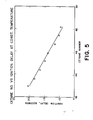
- T 20 temperatures listed in Table 1 were obtained, as discussed above, by first establishing the ignition delay curve (T 20 versus temperature) for that particular fuel. This necessitates the measurement of a number of T 20 values at different temperatures. In some cases it may be possible to correlate the ignition delay itself against cetane number, at least over a narrow band of cetane numbers, provided the measurement temperature remained constant at some appropriate value. Eight different blends of catalytically hydrodewaxed product and #2 fuel oil were tested, to encompass a range of approximately 6 cetane units (42.94 to 48.8). The ignition delay of each of these fuels blends measured at a constant temperature of 268°C (+ 0.3°C), is plotted against the cetane number in Figure 5. The resultant correlation is very good. Calibration curves of this type may be useful for rapidly detecting small deviations of the cetane quality of refinery streams from a specified value, or for use at a blending terminal to establish the desired cetane rating.
- the block 11 was a stainless steel cylinder with a diameter of 11.4 cm (4.5 inches) and a height of 16.5 cm (6.5 inches).
- the ignition cavity 12 was 3.8 cm deep (1.5 inches).
- Microprocessor 24 was a Hewlett Packard HP9825B and fuel injector 25 was a "repeating dispenser" supplied by Supelco, Inc., Bellefont, PA, Catalog No. 2-0943.
Landscapes
- Chemical & Material Sciences (AREA)
- Health & Medical Sciences (AREA)
- Life Sciences & Earth Sciences (AREA)
- Biochemistry (AREA)
- Engineering & Computer Science (AREA)
- Pathology (AREA)
- Immunology (AREA)
- General Physics & Mathematics (AREA)
- General Health & Medical Sciences (AREA)
- Physics & Mathematics (AREA)
- Analytical Chemistry (AREA)
- Oil, Petroleum & Natural Gas (AREA)
- Medicinal Chemistry (AREA)
- Food Science & Technology (AREA)
- General Chemical & Material Sciences (AREA)
- Chemical Kinetics & Catalysis (AREA)
- Investigating Or Analyzing Materials Using Thermal Means (AREA)
- Combined Controls Of Internal Combustion Engines (AREA)
Abstract
Description
- This invention relates to an apparatus and methods for rapidly determining the ignition behavior of distillate fuels and more particularly to the measurement of ignition delay as a function of temperature.
- The ignition quality of distillate fuels is defined by several parameters, one of which is the cetane number. Cetane number measurements are described, for example, in ASTM STANDARD TEST METHOD FOR IGNITION QUALITY OF DIESEL FUELS.
- Prior workers have observed that fuels having a low cetane number often have a high ignition delay, that is the time between the exposure of a fuel to ignition temperatures and its actual ignition. This is discussed by R. W. Hurn and K. J. Hughes in "Combustion Characteristics of Diesel Fuel as Measured in a Constant Volume Bomb," S.A.E. Quarterly Transactions, Vol. 6, No. 1, 1952.
- However, the prior art has not attempted to measure cetane number by measuring ignition delay because ignition delay measurement techniques do not provide the level of accuracy and reproducibility which is required for the rapid comparison of the relative ignition behavior of distillate fuel samples and for the estimation of their absolute cetane number. It is desirable to provide a rapid, accurate technique for assessing the ignition properties of fuels for products and process research and development work and in refinery operations as a quality control guide. Such a tool could be useful in terminal operations and by large volume purchasers wishing to check fuel quality.
- In accordance with the present invention, the ignition delay of distillate fuel is measured by apparatus which includes a block having an ignition cavity. The block is heated to a temperature above the ignition temperature of the fuel and then allowed to cool slowly. As it cools, samples of fuel are injected into the ignition cavity. A pressure transducer and a thermocouple measure the pressure and temperature, respectively, in the cavity. For each injected sample, the time between injection of a sample and ignition as indicated by a peak in measured cavity pressure or cavity temperature. The ignition delay is recorded as a function of the cavity temperature prior to fuel injection. Fuel injection or measurement of the ignition delay is done with the aid of a digital computer.
- Using the temperature required for a given ignition delay, the cetane rating of distillate fuels may be estimated from a calibration curve established by comparing unit data with results from the ASIM cetane number test. It has been found that the ignition temperatures of the tested distillate fuels fall on a smooth correlation curve which can be used to provide cetane number estimates for unknown fuels. These have been found to be in excellent agreement with observed ASTM values.
-
- Fig. 1 depicts the block and ignition cavity;
- Fig. 2 is a block diagram of the measurement system;
- Fig. 3 shows measured ignition delay as a function of temperature; and
- Fig. 4 shows ignition temperature as a function of ASTM cetane number.
- Referring to Fig. 1, the ignition delay of a distillate fuel is measured by an apparatus which includes a block 11 having an
ignition cavity 12. Aheater 13 heats the block to an elevated temperature above the ignition temperature of the fuel. An injector 14 injects samples of fuel into the ignition cavity as the block cools from the elevated temperature.Pressure transducer 15 measures the pressure in the cavity.Thermocouples -
Solenoid valve 18 is connected between a source of oxygen and theignition cavity 12 to flush it with oxygen which is exhausted through the solenoid actuatedvalve 19.Solenoid valve 20 supplies oxygen to one side ofpressure transducer 15. Apressure relief valve 22 and apressure gauge 23 complete the ignition apparatus. - The apparatus is controlled by a digital computer which also records the data as shown in Fig. 2.
Microprocessor 24 controls afuel injection system 25 which supplies fuel samples at precise times to the ignition cavity.Pressure transducer 15 andthermocouples microprocessor 24 which measures the ignition delay as the time between injection of a sample and ignition as indicated by a peak in measured cavity pressure or cavity temperature. Themicroprocessor 24 records the ignition delay as a function of cavity temperature prior to fuel injection. - A plotter/
printer 26 is provided to produce outputs. Aninput device 27, such as a keyboard, supplies the starting parameters to the microprocessor. - The operation of the system is as follows. To establish the ignition delay vs. temperature curve for a given fuel, the stainless steel block 11 and the
ignition cavity 12 are allowed to equilibrate at about 6°C (10°F) above the expected ignition temperature. The temperature of the block is then allowed to drop at a steady rate about 0.2 °C/minute (1/3°F minute) through the duration of the experiments. The injector 14 is a 1 ml syringe filled with the fuel under investigation with the syringe needle inserted into the injection cavity through the injection port. Theinjector 25 is a simple, auto injector that accurately injects 1/50th of the volume of the syringe upon actuation by the controllingmicroprocessor 24. - The
microprocessor 24 requires the starting parameters of the run, such as the starting temperature, number of data points desired, and the temperature interval between data points. It then monitors the cavity and block temperatures until the desired starting temperature has been obtained. The three solenoid valves 18-20 are open throughout this phase, maintaining a flush of pure oxygen through the system. As soon as the starting temperature has been obtained, the three valves 18-20 are closed in sequence, and over the next 12 seconds the average temperature of the cavity is accurately measured. The injector 14 is then actuated, injecting 20 microliters of fuel into the cavity. An electronic timer inmicroprocessor 24 is simultaneously started and the cavity pressure, temperature, and time are monitored in a rapid response loop. Ignition is recognized by themicroprocessor 24 by the extremely sharp pressure and temperature spikes registered upon initiation of combustion. The average cavity temperature just prior to injection and the time interval between injection and ignition are printed. - The solenoid valves 18-20 are reopened, and the products of combustion flushed out by the stream of fresh oxygen. The
microprocessor 24 once again starts to monitor the cavity temperature, until the next desired temperature is reached, when the process is repeated. An ignition delay of 40 seconds was chosen as defining no ignition. Themicroprocessor 24 continues the experiment until three successive no ignition conditions have been registered before halting the run. The microprocessor also handles data manipulation, reduction and tabulation. The final output is an auto-scales plot of the ignition delay vs. cavity temperatures. - Once the initial parameters have been defined and the fuel is loaded into the syringe, the unit requires no operator attention. If there is no possibility of an educated guess of the unknown fuel's ignition temperature, a rapid prior scan may be performed over a wide temperature range using large temperature intervals between data points, to establish the region of interest. The actual experiment can then be carried out, over this smaller temperature range with data points separated by smaller temperature intervals.
- Fig. 3 is representative of the type of data obtained by the invention. It is seen that there is almost no random scatter of data points. A duplicate run, using the same fuel, was performed a few days later. The two curves superimpose on each other almost exactly, and the agreement between the temperature required for a 20 second ignition delay (T20) obtained in the two cases was excellent, indicating the high degree of reproducibility of the data.
- A total of 9 samples were analyzed. Seven were straight run No. 2 type diesel fuels (Table 1, Samples 1-8). Two were somewhat lighter jet fuels (Samples 9 and 10). All cetane numbers reported were obtained by outside analyses using the ASTM method.

- Fig. 4 is a plot of the ignition temperature vs. ASTM cetane number for each of the fuels listed in Table 1. The error bar on the ignition temperature measurement is estimated to be no more than + 0.5°C. The normally accepted error bar on cetane number measurement is + 2 CN units as referred to in the ASTM Standard Test. Examining Fig. 4, it is apparent that the ignition temperature of the distillate fuels tested fall on a smooth correlation curve.
- Using this correlation curve, the cetane number of four other distillate fuels were estimated and compared with the predictions with the observed ASTM values in Table 2 below. The estimated and ASTM results were in very good agreement.

- Each of the T20 temperatures listed in Table 1 was obtained, as discussed above, by first establishing the ignition delay curve (T20 versus temperature) for that particular fuel. This necessitates the measurement of a number of T20 values at different temperatures. In some cases it may be possible to correlate the ignition delay itself against cetane number, at least over a narrow band of cetane numbers, provided the measurement temperature remained constant at some appropriate value. Eight different blends of catalytically hydrodewaxed product and #2 fuel oil were tested, to encompass a range of approximately 6 cetane units (42.94 to 48.8). The ignition delay of each of these fuels blends measured at a constant temperature of 268°C (+ 0.3°C), is plotted against the cetane number in Figure 5. The resultant correlation is very good. Calibration curves of this type may be useful for rapidly detecting small deviations of the cetane quality of refinery streams from a specified value, or for use at a blending terminal to establish the desired cetane rating.
- In an exemplary embodiment of the invention, the block 11 was a stainless steel cylinder with a diameter of 11.4 cm (4.5 inches) and a height of 16.5 cm (6.5 inches). The
ignition cavity 12 was 3.8 cm deep (1.5 inches).Microprocessor 24 was a Hewlett Packard HP9825B andfuel injector 25 was a "repeating dispenser" supplied by Supelco, Inc., Bellefont, PA, Catalog No. 2-0943.
Claims (10)
Applications Claiming Priority (2)
| Application Number | Priority Date | Filing Date | Title |
|---|---|---|---|
| US06/554,014 US4549815A (en) | 1983-11-21 | 1983-11-21 | Measurement of ignition characteristics of distillate fuels |
| US554014 | 1983-11-21 |
Publications (3)
| Publication Number | Publication Date |
|---|---|
| EP0143571A2 true EP0143571A2 (en) | 1985-06-05 |
| EP0143571A3 EP0143571A3 (en) | 1986-02-12 |
| EP0143571B1 EP0143571B1 (en) | 1989-01-04 |
Family
ID=24211706
Family Applications (1)
| Application Number | Title | Priority Date | Filing Date |
|---|---|---|---|
| EP84307604A Expired EP0143571B1 (en) | 1983-11-21 | 1984-11-05 | Measurement of ignition characteristics of distillate fuels |
Country Status (7)
| Country | Link |
|---|---|
| US (1) | US4549815A (en) |
| EP (1) | EP0143571B1 (en) |
| JP (1) | JPS60135751A (en) |
| AU (1) | AU580267B2 (en) |
| CA (1) | CA1235588A (en) |
| DE (1) | DE3475964D1 (en) |
| ZA (1) | ZA848395B (en) |
Cited By (3)
| Publication number | Priority date | Publication date | Assignee | Title |
|---|---|---|---|---|
| WO1989008253A1 (en) * | 1988-03-01 | 1989-09-08 | Senter For Industriforskning | Method and apparatus for determining the ability of heavy fuels to self-ignite under diesel conditions |
| FR2701118A1 (en) * | 1993-02-01 | 1994-08-05 | Elf Antar France | A method for measuring the cetane number of diesel engine fuel fuels and a device for carrying out this process. |
| WO2007126618A1 (en) * | 2006-03-28 | 2007-11-08 | Dresser, Inc. | Analysis of fuel combustion characteristics |
Families Citing this family (9)
| Publication number | Priority date | Publication date | Assignee | Title |
|---|---|---|---|---|
| BE1012672A3 (en) * | 1999-05-07 | 2001-02-06 | Clers Bertrand Des | Anticipation process and / or prevention of explosion and / or a mixture of ignition fuel / oxidizing agent. |
| US7005991B1 (en) | 1999-05-07 | 2006-02-28 | Bertrand Des Clers | Method for anticipating, delaying and/or preventing the risk of spontaneous combustion and/or explosion of an explosive atmosphere |
| DE102007027483A1 (en) * | 2007-06-14 | 2008-12-18 | Robert Bosch Gmbh | Method for determining a quality characteristic of a diesel fuel |
| US8532911B2 (en) * | 2010-02-24 | 2013-09-10 | GM Global Technology Operations LLC | Adaptive diesel engine control for cetane variations |
| AT509743B1 (en) * | 2010-05-11 | 2012-05-15 | Grabner Instr Messtechnik Gmbh | DEVICE FOR MEASURING THE FLASHPOINT OF LIQUIDS AND SOLIDS |
| RU2454661C2 (en) * | 2010-07-05 | 2012-06-27 | Федеральное автономное учреждение "25 Государственный научно-исследовательский институт химмотологии Министерства обороны Российской Федерации" | Method of predicting shelf life of hydrocarbon fuel in storage facilities |
| JP6190123B2 (en) * | 2013-02-18 | 2017-08-30 | 川崎重工業株式会社 | Fuel oil analyzer |
| US9556845B2 (en) * | 2013-03-12 | 2017-01-31 | Ecomotors, Inc. | Enhanced engine performance with fuel temperature control |
| US10697915B1 (en) | 2016-06-07 | 2020-06-30 | Precision Combustion, Inc. | Sensor for determining a physicochemical property of a liquid fuel |
Citations (4)
| Publication number | Priority date | Publication date | Assignee | Title |
|---|---|---|---|---|
| CH516799A (en) * | 1967-10-31 | 1971-12-15 | Universal Oil Prod Co | Device for analyzing hydrocarbons and mixtures containing hydrocarbons |
| US3778808A (en) * | 1972-01-17 | 1973-12-11 | G Stevens | Electronic weight monitor |
| GB1340731A (en) * | 1970-05-15 | 1974-01-30 | Universal Oil Prod Co | Method and apparatus for determining acomposition characteristic of a combustible fluid |
| GB1455423A (en) * | 1972-11-03 | 1976-11-10 | Clean Air Co | Pressurised oil burners |
Family Cites Families (9)
| Publication number | Priority date | Publication date | Assignee | Title |
|---|---|---|---|---|
| GB190719008A (en) * | 1907-08-23 | 1908-08-06 | Maurice Hans | Improvements in or relating to Variable Tension Thread Guides particularly applicable to Bobbin- or Yarn-winding Machines. |
| GB394736A (en) * | 1932-01-19 | 1933-07-06 | William Helmore | Improvements in or relating to testing combustible fluids |
| US3408856A (en) * | 1964-09-14 | 1968-11-05 | Gross Lewis | Methods and apparatus for determining flash point |
| US3670561A (en) * | 1970-01-30 | 1972-06-20 | Alf Hundere | Apparatus for determining the thermal stability of fluids |
| GB1474475A (en) * | 1974-09-06 | 1977-05-25 | Oertling Ltd | Flammability testing apparatus |
| US3985505A (en) * | 1974-11-21 | 1976-10-12 | Leco Corporation | Combustion system |
| JPS5240397A (en) * | 1975-09-26 | 1977-03-29 | Ajinomoto Co Inc | Mthod of measuring flash point |
| NL183677C (en) * | 1976-01-20 | 1988-12-16 | Inst Francais Du Petrole | METHOD FOR QUICK DETERMINATION OF AT LEAST A PETROLEUM PROPERTY OF GEOLOGICAL DEPOSITS BASED ON SMALL SAMPLES. |
| JPS57141541A (en) * | 1981-02-25 | 1982-09-01 | Kawasaki Steel Corp | Measuring apparatus for explosion limit of blast furnace gas |
-
1983
- 1983-11-21 US US06/554,014 patent/US4549815A/en not_active Expired - Fee Related
-
1984
- 1984-10-26 ZA ZA848395A patent/ZA848395B/en unknown
- 1984-11-02 AU AU34956/84A patent/AU580267B2/en not_active Ceased
- 1984-11-05 DE DE8484307604T patent/DE3475964D1/en not_active Expired
- 1984-11-05 EP EP84307604A patent/EP0143571B1/en not_active Expired
- 1984-11-08 CA CA000467333A patent/CA1235588A/en not_active Expired
- 1984-11-20 JP JP59245870A patent/JPS60135751A/en active Pending
Patent Citations (4)
| Publication number | Priority date | Publication date | Assignee | Title |
|---|---|---|---|---|
| CH516799A (en) * | 1967-10-31 | 1971-12-15 | Universal Oil Prod Co | Device for analyzing hydrocarbons and mixtures containing hydrocarbons |
| GB1340731A (en) * | 1970-05-15 | 1974-01-30 | Universal Oil Prod Co | Method and apparatus for determining acomposition characteristic of a combustible fluid |
| US3778808A (en) * | 1972-01-17 | 1973-12-11 | G Stevens | Electronic weight monitor |
| GB1455423A (en) * | 1972-11-03 | 1976-11-10 | Clean Air Co | Pressurised oil burners |
Non-Patent Citations (1)
| Title |
|---|
| SAE QUARTERLY TRANSACTIONS, vol. 6, no. 1, January 1952, pages 24-35, New York, US; R.W. HURN et al. "Combustion characteristics of Diesel fuels as measured in a constant-volume bomb" * |
Cited By (7)
| Publication number | Priority date | Publication date | Assignee | Title |
|---|---|---|---|---|
| WO1989008253A1 (en) * | 1988-03-01 | 1989-09-08 | Senter For Industriforskning | Method and apparatus for determining the ability of heavy fuels to self-ignite under diesel conditions |
| FR2701118A1 (en) * | 1993-02-01 | 1994-08-05 | Elf Antar France | A method for measuring the cetane number of diesel engine fuel fuels and a device for carrying out this process. |
| EP0610118A1 (en) * | 1993-02-01 | 1994-08-10 | Elf Antar France | Measuring method for the cetane index of diesel engine fuels and apparatus for carrying out this method |
| US5457985A (en) * | 1993-02-01 | 1995-10-17 | Elf Antar France | Process for measuring the cetane number of supply fuels for diesel engines and apparatus for performing this process |
| WO2007126618A1 (en) * | 2006-03-28 | 2007-11-08 | Dresser, Inc. | Analysis of fuel combustion characteristics |
| US7529616B2 (en) | 2006-03-28 | 2009-05-05 | Dresser, Inc. | Analysis of fuel combustion characteristics |
| CN101416053B (en) * | 2006-03-28 | 2017-06-06 | 德雷瑟股份有限公司 | Analysis of fuel combustion characteristics |
Also Published As
| Publication number | Publication date |
|---|---|
| ZA848395B (en) | 1986-06-25 |
| US4549815A (en) | 1985-10-29 |
| EP0143571A3 (en) | 1986-02-12 |
| CA1235588A (en) | 1988-04-26 |
| DE3475964D1 (en) | 1989-02-09 |
| AU3495684A (en) | 1985-05-30 |
| JPS60135751A (en) | 1985-07-19 |
| AU580267B2 (en) | 1989-01-12 |
| EP0143571B1 (en) | 1989-01-04 |
Similar Documents
| Publication | Publication Date | Title |
|---|---|---|
| EP0143571B1 (en) | Measurement of ignition characteristics of distillate fuels | |
| US9709477B2 (en) | Apparatus and methodology for measuring properties of microporous material at multiple scales | |
| US4543819A (en) | Vapor-liquid ratio analyzer | |
| Allard et al. | Diesel fuel ignition quality as determined in the ignition quality tester (IQT) | |
| US8646312B2 (en) | Method and system for measuring RON and MON values for light distillates | |
| EP2087346B1 (en) | A method of measuring cetane values for middle distillate fuels | |
| JPH10148631A (en) | Calibration method for chromatography column | |
| EP3870971B1 (en) | Method and apparatus for calculating derived cetane numbers | |
| US11454602B2 (en) | Sensor for determining a physicochemical property of a liquid fuel | |
| US7872465B2 (en) | Apparatus and methods for evaluating material volatility | |
| CN109190238A (en) | A method of measurement austenitic stainless steel hydrogen trap activation energy | |
| US20050175510A1 (en) | Analyzer for automatic rapid analysis of the acetaldehyde content of pet products, particularly preforms, and its operative process | |
| DE10231269B4 (en) | Determination of the gas quality of combustion gases by measuring thermal conductivity, heat capacity and carbon dioxide content | |
| US3407041A (en) | Method for the quantitative determination of nitrogen and oxygen in metal samples | |
| EP1579206B1 (en) | A method and apparatus for keeping constant the retention times in a gaschromatographic analysis | |
| DE19638498C1 (en) | Gas sensor operating and calibrating method for high temperature use, e.g. as Ga2O3 gas sensor | |
| Gislason et al. | Calibration transfer of chemometric models based on process nuclear magnetic resonance spectroscopy | |
| JP2648375B2 (en) | Method and apparatus for measuring the self-ignition ability of heavy oil under diesel conditions | |
| SU1627950A1 (en) | Method of determining substance-formation enthalpy | |
| Bouquet | Determination of hydrogen content of petroleum products using a low resolution pulsed nmr spectrometer: Applications to light cuts, distillates and residues | |
| Chryssanthakis et al. | High Temperature Triaxial Tests With Ultrasonic Measurementson Ekofisk Chalk | |
| CN115901836A (en) | Method for measuring gas saturation of shale gas by utilizing nuclear magnetic resonance phenomenon | |
| KR910006227B1 (en) | Method and apparatus for determining the ability of heavy fuels to self-ignite under diessl conditions | |
| Gosset et al. | Improvement of the Cowan method for thermal diffusivity determination | |
| Tighe et al. | Parametric analysis of the propagation of uncertainties in sorption measurements made with a pressure-decay apparatus |
Legal Events
| Date | Code | Title | Description |
|---|---|---|---|
| PUAI | Public reference made under article 153(3) epc to a published international application that has entered the european phase |
Free format text: ORIGINAL CODE: 0009012 |
|
| AK | Designated contracting states |
Designated state(s): BE DE FR GB IT NL |
|
| PUAL | Search report despatched |
Free format text: ORIGINAL CODE: 0009013 |
|
| AK | Designated contracting states |
Designated state(s): BE DE FR GB IT NL |
|
| 17P | Request for examination filed |
Effective date: 19860711 |
|
| 17Q | First examination report despatched |
Effective date: 19880330 |
|
| GRAA | (expected) grant |
Free format text: ORIGINAL CODE: 0009210 |
|
| AK | Designated contracting states |
Kind code of ref document: B1 Designated state(s): BE DE FR GB IT NL |
|
| REF | Corresponds to: |
Ref document number: 3475964 Country of ref document: DE Date of ref document: 19890209 |
|
| ET | Fr: translation filed | ||
| ITF | It: translation for a ep patent filed |
Owner name: MODIANO & ASSOCIATI S.R.L. |
|
| PLBE | No opposition filed within time limit |
Free format text: ORIGINAL CODE: 0009261 |
|
| STAA | Information on the status of an ep patent application or granted ep patent |
Free format text: STATUS: NO OPPOSITION FILED WITHIN TIME LIMIT |
|
| 26N | No opposition filed | ||
| PGFP | Annual fee paid to national office [announced via postgrant information from national office to epo] |
Ref country code: DE Payment date: 19910910 Year of fee payment: 8 |
|
| PGFP | Annual fee paid to national office [announced via postgrant information from national office to epo] |
Ref country code: FR Payment date: 19910920 Year of fee payment: 8 |
|
| PGFP | Annual fee paid to national office [announced via postgrant information from national office to epo] |
Ref country code: GB Payment date: 19910925 Year of fee payment: 8 |
|
| PGFP | Annual fee paid to national office [announced via postgrant information from national office to epo] |
Ref country code: BE Payment date: 19911024 Year of fee payment: 8 |
|
| ITTA | It: last paid annual fee | ||
| PGFP | Annual fee paid to national office [announced via postgrant information from national office to epo] |
Ref country code: NL Payment date: 19911130 Year of fee payment: 8 |
|
| PG25 | Lapsed in a contracting state [announced via postgrant information from national office to epo] |
Ref country code: GB Effective date: 19921105 |
|
| PG25 | Lapsed in a contracting state [announced via postgrant information from national office to epo] |
Ref country code: BE Effective date: 19921130 |
|
| BERE | Be: lapsed |
Owner name: MOBIL OIL CORP. Effective date: 19921130 |
|
| PG25 | Lapsed in a contracting state [announced via postgrant information from national office to epo] |
Ref country code: NL Effective date: 19930601 |
|
| GBPC | Gb: european patent ceased through non-payment of renewal fee |
Effective date: 19921105 |
|
| NLV4 | Nl: lapsed or anulled due to non-payment of the annual fee | ||
| PG25 | Lapsed in a contracting state [announced via postgrant information from national office to epo] |
Ref country code: FR Effective date: 19930730 |
|
| PG25 | Lapsed in a contracting state [announced via postgrant information from national office to epo] |
Ref country code: DE Effective date: 19930803 |
|
| REG | Reference to a national code |
Ref country code: FR Ref legal event code: ST |